Impedance-Based Analysis for Power Electronics-Based Systems
AUTHOR
Y. LIAO - Electrical System Design, Energinet

Summary
Converter-driven small-signal oscillation issues have been increasingly identified in modern power systems. Impedance-based stability analysis has become an attractive method to tackle such issues, as they can be well applied for black-boxed systems. This article provides a summary of recent advances of impedance-based analysis for power electronics-based systems, based on the author’s PhD thesis. Chapter 1 first introduces the motivation of utilizing impedance-based analysis, and discusses the state of the art and research gaps. Then, Chapters 2-4 introduce the developed methodologies for the impedance-based modeling, the impedance-based stability analysis, and the application to the converter control design, respectively. Chapter 5 finally concludes the article, with discussions on industrial challenges and prospects.
keywords
grid forming - impedance measurement - impedance stability - passivity - small-signal analysis1. Introduction
The modern power systems have undergone significant changes in the past years due to the integration of renewable energies, such as wind and solar. As the key energy interfacing devices, power electronic converters are increasingly installed in power systems to achieve flexible energy generation and transmission. They behave very differently from the legacy synchronous generators – they bring less inertia because the lack of rotating mass; they are highly control dependent and act much faster and more flexibly; they have different protection schemes due to their limited overcurrent capability. Due to these new features, new types of instability issues are emerging in recent years, and the legacy analysis approaches developed for synchronous generator-based systems are no longer adequate for stability assessment. Thus, it is necessary to develop new analysis approaches that can be adaptively utilized for power electronics-based systems.
The converter control interaction is one of the major reasons that leads to new types of instability issues. The fast control dynamics of converters may interact with power system networks in some extreme grid conditions and result in oscillations that threaten the stable operation of power systems. The resultant oscillations may occur across a wide frequency range, ranging from a few hertz to a few thousand hertz, whose dynamics cannot be captured by the traditional phasor-based modeling method. Electromagnetic transient simulation has been identified as an adequate method to analyze such converter control interaction issues. However, it is time-consuming, and the simulation results cannot reveal much insight into the system design. Therefore, it is of significant value to develop new analytical approaches to analyzing the converter control interactions.
Converter control interactions are related to the small-signal dynamics, which can be captured by the linearized modeling. The commonly used linearized analysis approaches include the state-space analysis and frequency-domain analysis. The former one is powerful in analyzing certain oscillation modes and the time-domain responses, while the latter one is more advantageous in analyzing black-box systems because it utilizes transfer functions. Nowadays converter systems are usually developed by different manufacturers, where the control details are kept confidential, thus the frequency-domain analysis approach has become more popular. In particular, the impedance-based analysis is the typical method for the frequency-domain analysis, because impedance model offers a modular way to represent the converter dynamics at the defined points of connections – it can be easily verified by frequency scan measurement and can also be easily aggregated for large-scale system studies.
There are still some research gaps in terms of impedance-based modeling and analysis for converter systems, although they have been extensively studied in recent years. The PhD project identified these challenges and filled the gaps from three aspects: 1) impedance modeling approach; 2) impedance-based stability analysis approach; 3) application to converter control design.
1.1. Impedance modeling approach
Existing research works have studied the impedance modeling for grid-connected converters in different reference frames based on different assumptions.
Considering only the symetric inner-loop control dynamics, converter impedance model is usually reduced as a single-input single-output (SISO) model in the phase domain [1]. Such a SISO impedance is valid in the frequency range that is higher than the outer-loop control bandwidth. It can be used to analyze the control interactions induced by time delay of digital controllers.
When the converter outer-loop control dynamics are considered, the dynamic couplings among d and q axes are asymmetric. The converter impedance model cannot be simply represented by a SISO model; thus a MIMO impedance representation is necessary. And such a MIMO impedance model is also determined by the operating condition of the converter system due to linearization. Existing studies have derived the MIMO impedance model of converter systems in dq frame [2], modified sequence domain [3], as well as αβ frame [4]. Although they are mathematically equivalent, how to interpret these impedance models directly in phase domain considering the phase dependence behavior has not been fully revealed, which makes it difficult to develop the model verification approach.
On the other hand, the above impedance modeling efforts on converter systems are mainly focused on three-phase balanced conditions. How to derive a more generic impedance model under unbalanced or harmonic distorted grids has not been studied thoroughly.
To fill these gaps, this PhD work firstly develops an αβ-frame impedance modeling approach based on direct linearization in stationary frame and proposes its impedance measurement approach considering phase dependence behavior [P1]. Then, the impedance model is extended to the three-phase unbalanced grid conditions [P2]. Finally, the mathematical relationships between different linearized modeling methods under three-phase unbalanced grids are also derived and summarized [P3].
1.2. Impedance-based stability analysis approach
The classical impedance-based stability criterion is developed from the Nyquist stability criterion [5]. The impedance ratio is used as the system open-loop gain for stability analysis. When analyzing a SISO impedance ratio, the stability can be interpreted on individual impedance Bode diagrams, which allows for design-oriented studies and facilitates the impedance specification of subsystems [6]. However, such Bode-diagram-based analysis has a prerequisite that the impedance ratio shall have none right-half-plane (RHP) poles. For large-scale black-box converter-based systems, the exact pole / zero information of converter systems is usually unknown, which makes it difficult to apply the impedance-based stability criterion on individual Bode diagrams.
To fill this gap, this PhD work develops an impedance-based stability analysis approach based on black-box systems, considering the existence of open-loop RHP poles yet still utilizing the individual impedance Bode diagrams [P4].
1.3. Application to converter control design
The impedance-based stability analysis has been widely applied to design grid-connected converters for stability enhancement. For instance, the passivity-based impedance design is used to design the current controller of converter systems, which can resolve the instability induced by time delay [7]. By reducing the non-passive region of the converter systems, the phase-locked loop induced instability in weak grids can also be improved [8]. However, these studies are mainly focused on grid-following converters.
In recent years, grid-forming converters attract more attention because of their better performance in weak grids [9]. However, grid-forming converters may have more cascaded and tightly coupled control loops, which makes the controller design more difficult than grid-following converters. Their control interactions may also lead to instability under different grid conditions [10]. Therefore, this PhD work focuses on the application of impedance-based analysis in design of grid-forming converters for stability enhancement [P5], [P6].
In the rest of the article, the contributions of this PhD work in the above three aspects are described in Sections II-IV, respectively. Conclusions and prospects in extending the PhD work in industrial applications are summarized in Section V, and the references including the related publications are listed in Section VI.
2. Impedance Modeling Approach
2.1. αβ-frame impedance modeling and measurement approach [P1]
Figure 1(a) shows the conventional modeling steps for three-phase converter systems, which usually conduct the linearized modeling in dq frame around time-invariant operating points, and then transform the model back to αβ frame. In this PhD work, a different modeling approach by directly linearizing the converter system in αβ around a time-periodic operating trajectory is proposed, as shown in Figure 1(b).
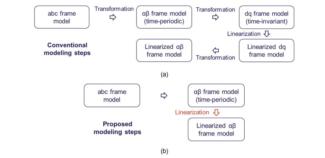
Figure 1 - Modeling steps for αβ-frame impedance models of three-phase converters.
(a) Conventional steps; (b) Proposed steps
Modeling converter system in αβ frame utilizes the complex-variable representation. It allows for capturing the frequency coupling dynamics of AC and DC variables using a three-port network. Figure 2 shows the three-port network representation by linearizing the power stage of the converter, where any AC-port variables shall be represented by two complex variables in the αβ frame, and the DC-port variable shall be presented by one complex variable.
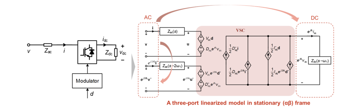
Figure 2 - Three-port model clarifying the couplings among AC and DC ports
The three-port model enables to establish a scalable modeling framework to represent not only circuit, but also any control scheme. For instance, a grid-following converter with current control, phase-locked loop (PLL) and DC voltage control, can be represented using different transfer function matrices in frequency domain, as the AC and DC variables are denoted in the same way. Figure 3 shows how to represent the grid-following converter by cascading different controllers with power stage according to the control scheme. Through such closed-loop control diagram, any transfer function can be derived, such as the AC-side input admittance and the AC-DC voltage transfer function.
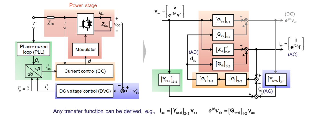
Figure 3 - Closed-loop frequency-domain modeling of a grid-following converter in αβ frame
The three-port variable representation also enables to reveal the frequency-coupling and phase-dependent dynamics, as illustrated in Figure 4. The left side of the arrow represents the time-domain representation, where the exponential operators are related to the steady-state operating trajectory around which the linearization is done. The right-side of the arrow represents the frequency-domain representation, where the dependence of operating trajectory is interpreted as a frequency shift and an initial phase rotation.

Figure 4 - Frequency-coupling and phase-dependent dynamics revealed by three-port variables
Based on the inherent coupling dynamics using the αβ-frame complex variables, a frequency-scan approach is also proposed to measure the converter impedance directly in αβ frame. It follows the flowchart in Figure 5, which includes three major steps:
- Perturbation injection: two frequency coupled perturbations needs to be injected at the AC side to excite two responses independently.
- Response analysis: discrete Fourier analysis can be used to extract the Fourier coefficients of different frequency components in the measured variables. However, the phase dependence shall also be considered to compensate the impact of operating trajectory on the Fourier coefficients.
- Transfer function calculation: the transfer function can be finally calculated based on the Fourier coefficients.
Compared with the classical frequency scan approach to measuring the converter dq-frame impedance, this measurement approach does not need a PLL for dq-transformation, which is simpler in calculation.

Figure 5 - Proposed frequency-scan approach for measuring converter frequency-domain models in αβ frame
Figure 6 shows the experimental verification of the modeling approach and the frequency-scan measurement approach on a grid-following converter. Figure 6(a) shows the result of AC input admittance, while Figure 6(b) shows the result of AC-DC voltage transfer function. Since they are both transfer function matrices, the Bode diagrams of all the elements in the transfer function matrices are plotted. The blue lines denote the analytical model, the red crosses denote the frequency-scan measurement considering phase dependence, and the yellow crosses denote the frequency-scan measurement without considering phase dependence It can been that only when considering the phase dependence, the frequency-domain model can be correctly measured.
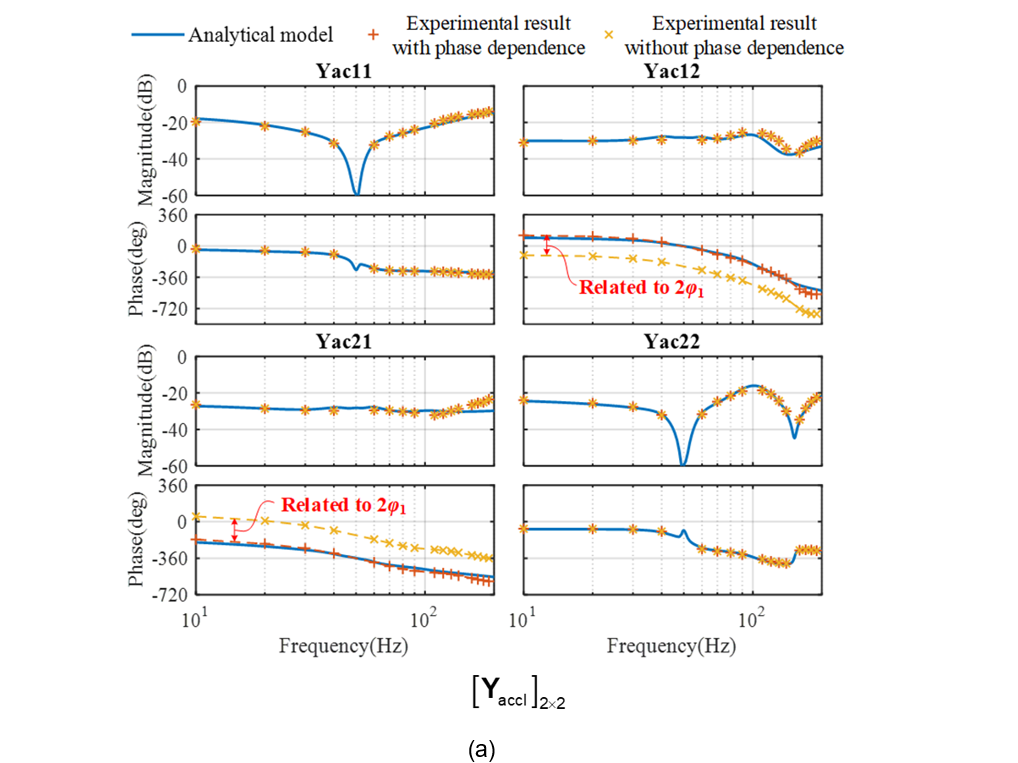
Figure 6 - Experimental verification of the modeling approach and the frequency-scan measurement approach. (a) AC input admittance; (b) AC-DC voltage transfer function
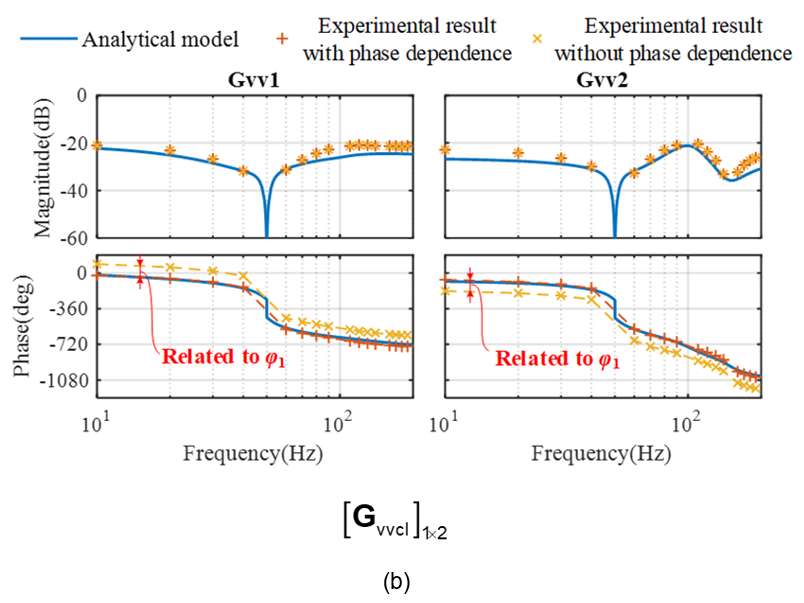
Figure 6 - Experimental verification of the modeling approach and the frequency-scan measurement approach. (a) AC input admittance; (b) AC-DC voltage transfer function
2.2. αβ-frame impedance modeling extended to unbalanced grids [P2]
The frequency-domain model of converter shown in Figure 3 can also be extended to unbalanced grid conditions. The time-domain responses can still be represented by three-port variables. However, each time-domain variable may consist of multiple frequency components in steady-state, its frequency domain response shall be represented by more frequency coupling terms. Such kind of frequency coupling dynamics can be characterized by harmonic transfer functions (HTFs) based on linear time-periodic system theory. Therefore, the frequency domain model of a grid-following converter can be still represented by the same closed-loop control diagram, as shown in Figure 7(a). However, it is worth noting that each transfer function matrix is now represented by harmonic transfer functions which have higher matrix order. Its frequency domain response can be denoted as Figure 7(b), where each time-domain variable now corresponds to more frequency coupling terms. The number of frequency terms depends on the existing number of harmonics in the steady states.
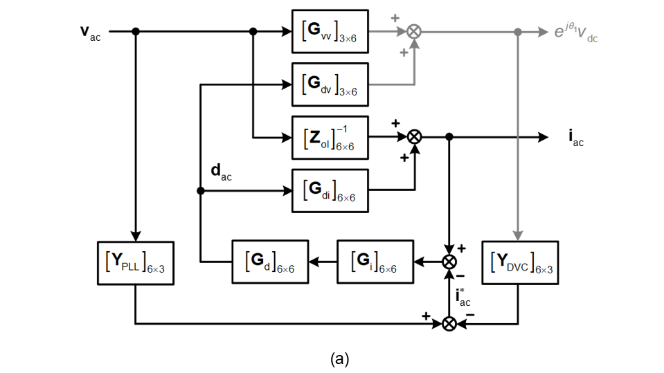
Figure 7 - Frequency-domain model of a grid-following converter in αβ frame generalized in unbalanced grids.
(a) Closed-loop control diagram with higher-order HTFs; (b) Frequency-domain response of time-domain variables
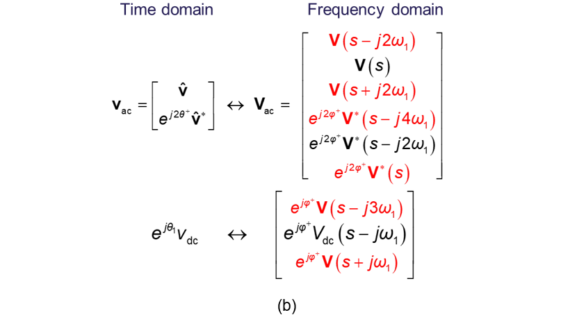
Figure 7 - Frequency-domain model of a grid-following converter in αβ frame generalized in unbalanced grids.
(a) Closed-loop control diagram with higher-order HTFs; (b) Frequency-domain response of time-domain variables
Similarly, the frequency-domain model of converter under unbalanced grid conditions can be verified by frequency scan measurement. Figure 8 shows the verification of the converter AC input admittance. Now considering unbalanced grids, the admittance matrix is a six-by-six matrix. For simplicity, all the elements in the second column are shown for verification.
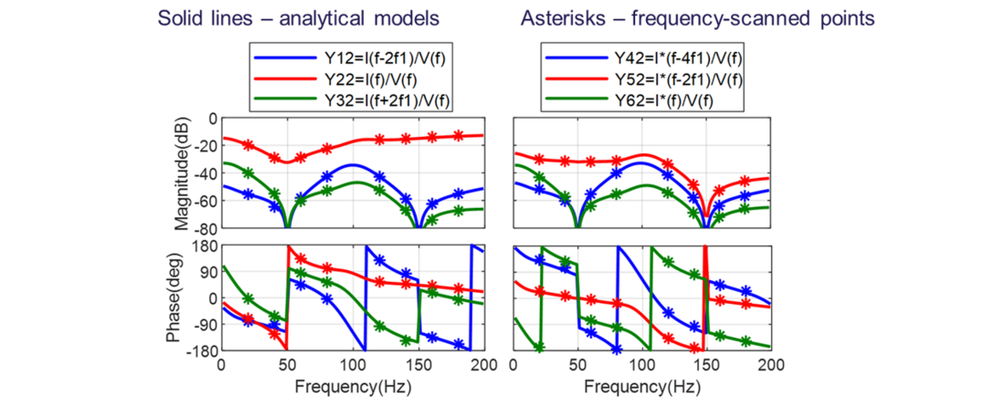
Figure 8 - Frequency-scan verification of the AC input admittance of the grid-following converter under unbalanced grids
2.3. Mathematical relationships of different linearized modeling approach in unbalanced grids [P3]
The modeling approach presented in the previous sub-section is based on linearized modeling around time-periodic trajectory in αβ frame, which follows the principle of harmonic state-space (HSS) modeling. Actually, there are also other modeling approaches developed for converter systems under unbalanced grid conditions, such as dynamic phasor (DP) modeling and generalized DQ (GDQ) modeling. To investigate the mathematical relationships among different modeling approaches, a critical overview is conducted. It ends up with a unified modeling framework for different linearized modeling methods, which is summarized in Figure 9. The first column represents the procedures for HSS modeling, the second column represents the procedures for DP modeling, and the third column represents the GDQ modeling. It is found that all these modeling methods can yield a unified frequency-domain model, which is the HSS (or HTF) model. The exact mathematical relationships among different modeling procedures are revealed by the red arrows in Figure 9.
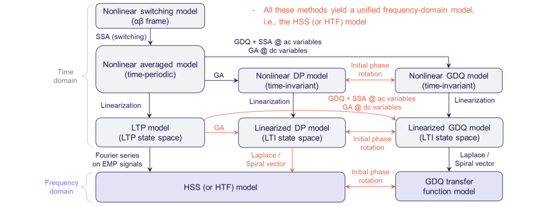
Figure 9 - Unified framework for different linearized modeling methods applied to converter systems under unbalanced grid conditions
3. Impedance-Based Stability Analysis Approach
This section presents the proposed impedance-based stability analysis approach for a single-input single-output (SISO) non-minimum phase systems, and elaborates how it can be generalized for multi-input and multi-output (MIMO) systems. Detailed case studies can be found in [P4] for SISO systems and [P2], [P8], [P9] for MIMO systems.
3.1. Stability analysis approach for single-input single-output (SISO) systems [P4]
The stability analysis is still based on the Nyquist stability criterion, however, the analysis approach enables to implement the analysis directly based on individual impedance Bode diagrams even though the loop gain may have right-half-plane (RHP) poles. The procedures for the proposed method are summarized in Figure 10, which include four steps:
- Choose the loop gain (L=Z1/Z2) as a proper function. This is a pre-requisite for the Nyquist stability criterion. If the impedance ratio can be defined with its high-frequency response tending to approaching zero, the encirclement of the loop gain around (-1, 0) on the Nyquist diagram can be determined by only considering frequency response in limited frequency ranges, thus the analysis on Bode diagram can be used.
- Identify the number of open-loop RHP poles, i.e., P. It can be calculated as the sum of RHP pole number in Z1 and RHP zero number in Z2. These information can be read from Bode diagrams based on magnitude and phase changing relationships even though the systems are purely black-box systems.
- Count the number of encirclements around (-1, 0), i.e., N. By mapping the Nyquist diagram of L to the individual Bode diagrams of Z1 and Z2, it is possible to directly count the number of encirclements on the two impedance Bode diagrams. The mapping principle is shown in Figure 11, where crossing boundaries are shifted by 180 degree of one impedance phase curve, the number of crossings shall be counted within the ER regions, and the crossing types shall be judged based on phase derivatives of the impedance curves.
- Stability check if P+N=0. This is based on the Nyquist stability criterion.
It is worth noting that since the method is purely based on Bode diagrams, it can be used for impedance specifications which offers design-oriented analysis.

Figure 10 - More general impedance-based stability analysis approach for SISO systems
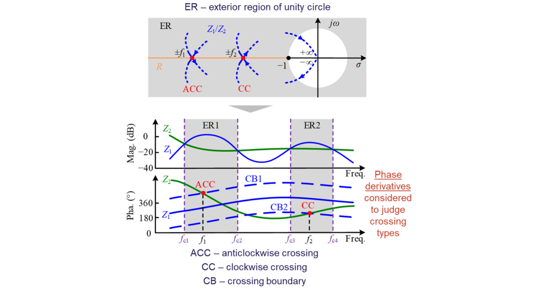
Figure 11 - Mapping from Nyquist diagram of L to individual impedance Bode diagrams of Z1 and Z2
3.2. Extension to multi-input multi-output (MIMO) systems [P7]
Although the proposed method is for SISO systems, it can also be extended to MIMO systems. Because for any MIMO system, its stability can always be analyzed by SISO equivalence. Then the SISO-based stability analysis on Bode diagrams can still be applied to count the number of RHP poles/zeros and the number of encirclements.
The typical methods using SISO equivalences to study the stability of a MIMO system include
- Utilize generalized Nyquist stability criterion to calculate the all the eigenvalues of the loop gain matrix. Then, each eigenvalue is a SISO transfer function. [P8], [P9]
- Directly analyze the zero of the system characteristic equation. It can also be denoted by a SISO transfer function, thus its number of RHP zeros indicate the system’s closed-loop unstable poles. [P2]

4. Control Design of Grid-Forming Converters
The impedance-based modeling and stability analysis is conducted on a grid-forming converter for the control design and stability enhancement. The studies are considered for high-frequency and low-frequency stability analyses, respectively.
4.1. High-frequency stability analysis considering only inner-loop control [P5]
The converter inner-loop control is usually symmetric in dq frame, thus when studying the inner-loop control dynamics, the converter outer-loop dynamics impact can be neglected. Thus, a grid-forming converter’s output impedance can be derived as a SISO impedance, as represented by Zo(s) in Figure 12. Since Zo(s) only considers inner-loop control dynamics, its effective frequency range should be beyond the outer-loop control bandwidth, thus the stability studied here is called as high-frequency stability analysis.
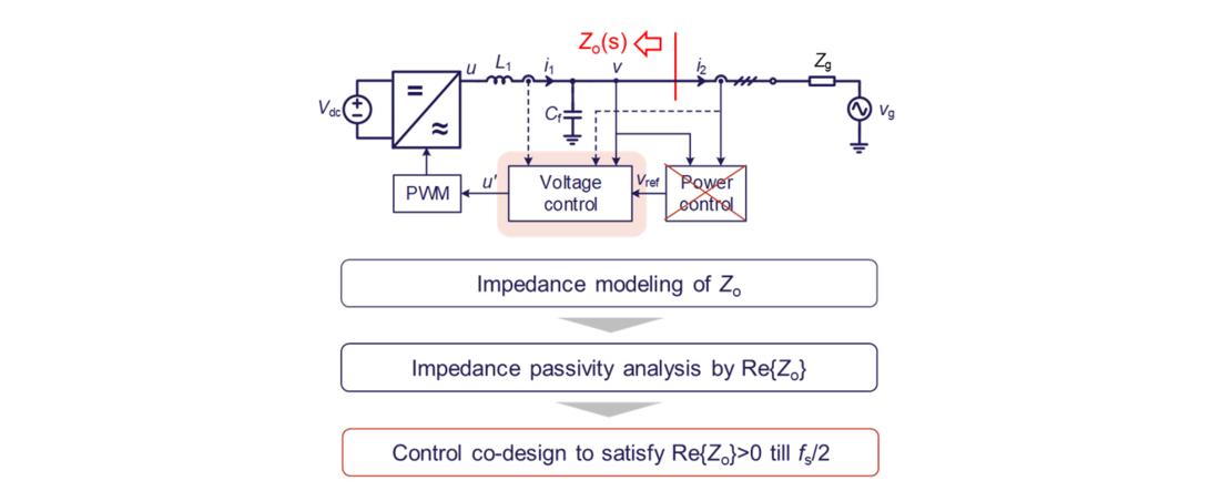
Figure 12 - High-frequency dynamic analysis by considering inner-loop control only
The passivity-based impedance analysis is utilized here for controller design. Its principle can be illustrated as:
- If Re{Zo}<0 in certain frequency range, it is indicated that converter impedance is non-passive. In such cases, the converter may interact with grid impedance and result in instability risks.
- If Re{Zo}>0 can be ensured by inner-loop control design, the converter impedance can be designed as passive. Then, it will bring no risks of instability when interacting with any kind of passive grid impedance.
The voltage control of grid-forming converter can be designed in multiple ways. This work studies three typical voltage controllers, as listed in Table 1. The control diagrams are shown in Figure 13. The passivity analysis and its potential instability risks when the virtual impedance control is not designed are summarized. Accordingly, to enhance the stability, the passivity-based controller co-design considering virtual impedance (Zv) is proposed. The design conditions are also summarized in Table 1.
| Control type | Single-loop control | Dual-loop control | Dual-loop control with voltage feedback decoupling |
|---|---|---|---|
| Control diagram | Figure 13(a) | Figure 13(b) without Hv | Figure 13(b) with Hv |
| Passivity analysis without virtual impedance (Zv) | Non-passive frequency range locates in the low-frequency range | Non-passive frequency range locates in the high-frequency range | Non-passive frequency range locates in the high-frequency range |
| Instability risk | Oscillations may happen when Zo interacts with a resonant grid impedance | Oscillations may happen when Zo interacts with an inductive grid impedance | Oscillations may happen when Zo interacts with an inductive grid impedance |
| Passivity-based controller co-design conditions | 1) Gv design: High-frequency integral-dominant controller 2) Zv design: | 1) Gv design: High-frequency integral-dominant controller | 1) Gv design: High-frequency integral-dominant controller 2) Zv design: |
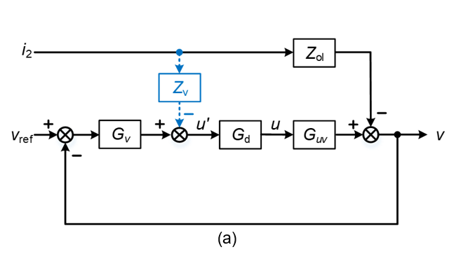
Figure 13 - Typical voltage control diagrams of a grid-forming converter.
(a) Single-loop control; (b) Dual-loop control with or without voltage feedback decoupling
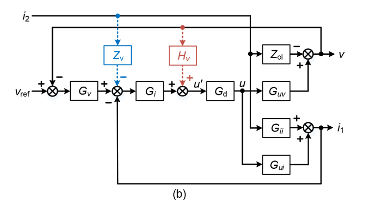
Figure 13 - Typical voltage control diagrams of a grid-forming converter.
(a) Single-loop control; (b) Dual-loop control with or without voltage feedback decoupling
The passivity-based stability analysis and control design for all the control types have been verified by experiments. Detailed case studies can be found in [P5]. Here, for simplicity, only one case study with dual-loop control is presented for illustration. Figure 14(a) shows the circuit diagram for experiment. Figure 14(b) shows the impedance-based stability without and with virtual impedance control. It can be seen that without virtual impedance, Zo has negative resistance in the frequency range higher than fs/6. According to the impedance-based stability analysis, it is unstable when Zo interacts with the grid impedance Zg.
However, when Zv is co-designed with other controllers satisfying the condition listed in Table 1, Zo becomes passive. Therefore, there is no instability risk when Zo interacts with the grid impedance Zg. Figure 14(c) provides the experimental waveforms of this case study. It can be seen that when Zv is enabled, the high-frequency oscillations can be mitigated and the stability is improved.
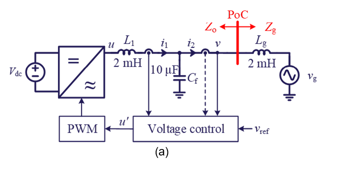
Figure 14 - Experimental verification of the passivity-based stability analysis and control design of grid-forming converter with dual-loop control
a) Circuit diagram and parameters; (b) Impedance-based stability analysis; (c) Experimental waveforms
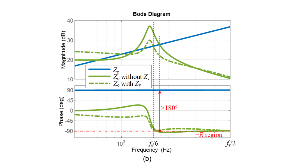
Figure 14 - Experimental verification of the passivity-based stability analysis and control design of grid-forming converter with dual-loop control
a) Circuit diagram and parameters; (b) Impedance-based stability analysis; (c) Experimental waveforms
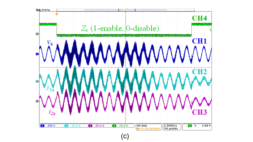
Figure 14 - Experimental verification of the passivity-based stability analysis and control design of grid-forming converter with dual-loop control
a) Circuit diagram and parameters; (b) Impedance-based stability analysis; (c) Experimental waveforms
4.2. Low-frequency stability analysis considering all control loops [P6]
To study the low-frequency stability, all the control loops of the grid-forming converter need to be considered. The converter impedance should be modeled as a MIMO impedance, as denoted by ZVSC(s) in Figure 15, where the study flow is also introduced.
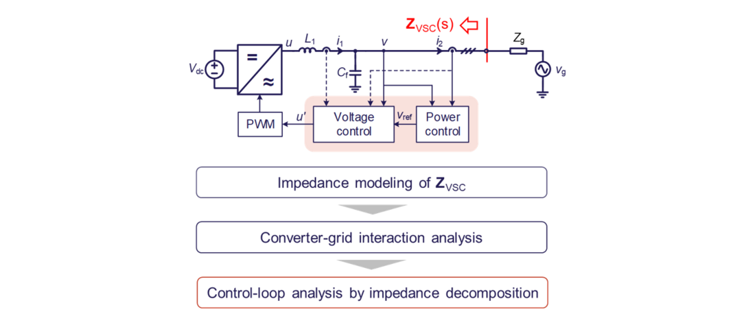
Figure 15 - Low-frequency dynamic analysis considering all control loops
First, the impedance modeling and stability analysis are conducted to study the converter-grid interaction. Since the impedances are modeled as MIMO impedances, the generalized Nyquist stability criterion is utilized for stability analysis, as shown in Figure 16.
- Step 1 first analyzes the stability under a critical case when the grid short-circuit ratio (SCR) is 10. It is found that one of the eigenvalue has magnitude slightly higher than 0 dB at the clockwise crossing (CC) frequency, indicating unstable. It is also implied that the high gain of λ1 around the fundamental frequency tends to destabilize the system.
- Step 2 considers the impedance decomposition of ZVSC and Zg, since the eigenvalue of loop gain L should be bounded by the singular values. Such decomposition reveals that the high gain of λ1 is contributed mainly by the high gain of converter impedance around the fundamental frequency.
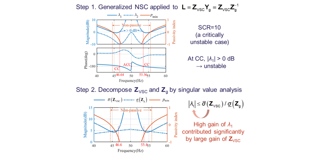
Figure 16 - Converter-grid interaction analysis based on the generalized Nyquist stability criterion and converter-grid impedance decomposition
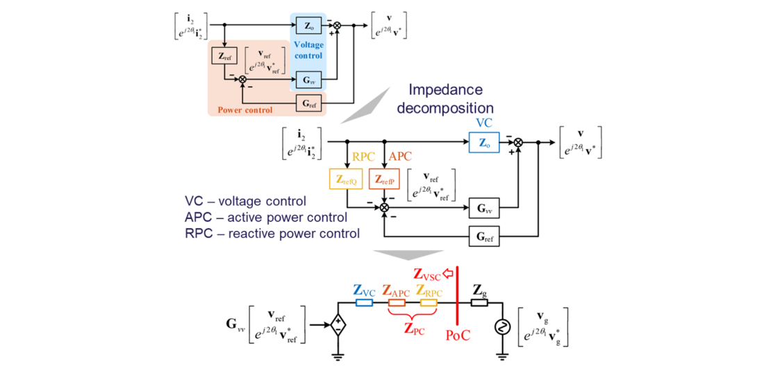
Figure 17 - Impedance decomposition approach for grid-forming converter to present control-loop impact on impedance shaping
However, it is still unclear why the grid-forming converter has high gain in its impedance here, and which control loop affects it. Consequently, an impedance decomposition based on control loops is further proposed for design-oriented studies. Figure 17 shows the principle of the impedance decomposition. According to the impedance modeling diagram, the control loops can be decomposed in forward loops, and thus several series impedances can be used to characterize the contribution of different control loops in impedance shaping. This enables a simplified comparison of control-loop impact on Bode diagrams, whose implications can also be interpreted based on simpler transfer function models.
In this case, the droop-based power control and dual-loop voltage control are studied on the grid-forming converter. Through the impedance decomposition, the impacts of voltage control (VC), active power control (APC) and reactive power control (RPC) are compared on Bode diagrams in Figure 18. It is found that APC and VC both contribute significantly two the high gain of converter impedance around the fundamental frequency, thus they are to dominant loops that affect the stability. In contrast, RPC has weaker contribution, indicating it is an insensitive loop. Therefore, the stability can be improved effectively by reducing the magnitude of VC and APC impedances, according to the small-gain theory.
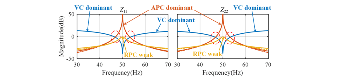
Figure 18 - Impedance shaping affected by different control loops of the grid-forming converter
Figure 19 shows the experimental verifications. It can be seen that tuning the VC and APC parameters can effectively improve the stability, while tuning RPC parameters cannot. Therefore, it verifies the conclusion based on the impedance-decomposition analysis.
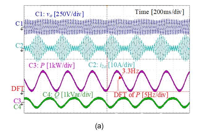
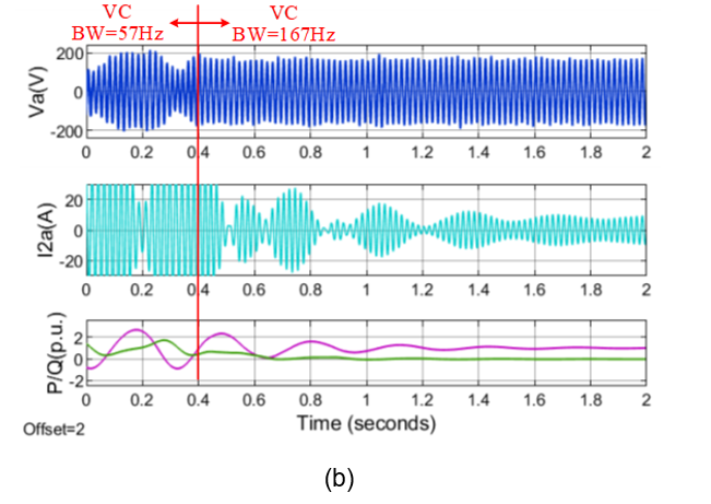
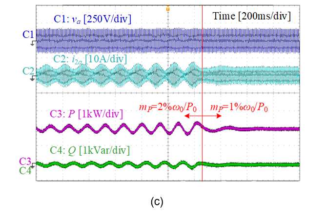
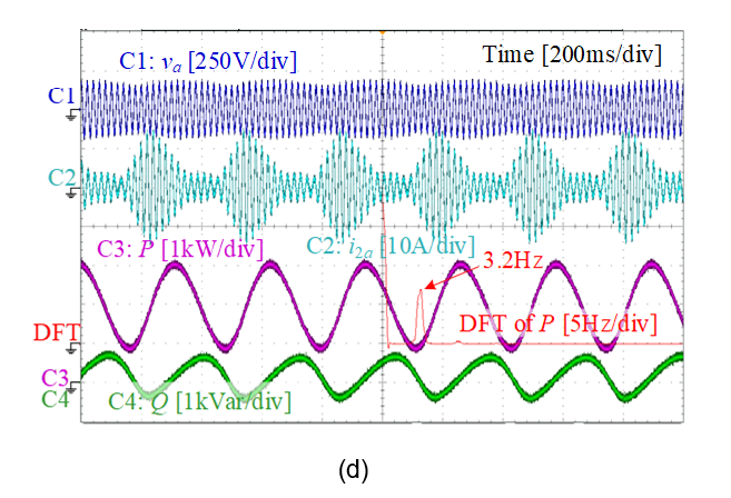
Figure 19 - Experimental verification of low-frequency stability analysis
(a) Critically unstable case with SCR = 10; (b) Stabilization by tuning only VC;
(c) Stabilization by tuning only APC; (d) Maintains critically unstable by tuning only RPC
5. Conclusions and Prospects
Although the impedance-based modeling and analysis has been applied to grid-connected converters for decades, this PhD work has paved a further way in its application in practice. More specifically, the distinguished contributions can be summarized as follows:
- The linearized modeling theory of converter-based systems has been revisited and unified, which provides a solid foundation to developing accurate frequency scan methods for converter model identification and verification. The frequency scan method has been applied by several TSOs in their EMT simulations to analyzing black-box vendor-specific models.
- The developed impedance-based stability analysis approach is also more general in application than the classical method, since it assumes black-box systems and can also deal with non-minimum phase systems. This makes it more readily applicable for industrial projects where more and more converters are integrated and aggregated, which may likely introduce non-minimum phase behavior at a certain aggregation point.
- The control design for grid-forming converters not only proves the effectiveness of the developed methodologies, but also offers more insights into how the grid-forming converter may influence the stability of the grid, which shows different conclusions compared with a grid-following converter. The stability analysis and control design methods have also been utilized by PV manufacturers through industrial project collaborations.
As this PhD focuses on the application of impedance-based analysis from the viewpoint of black-box system analysis, it has the potential to be an effective method in analyzing stability of future power systems with high penetration of power electronics. Based on the PhD work, the author has also done further research in exploring how the impedance-based analysis can be applied in power system-level studies and how it can offer more insights into the converter interoperability issues, which may help system operators identify the root cause of instability. New frequency-domain participation [P8] and sensitivity analysis [P9] approaches have been proposed on top of the black-box impedance analysis, which offer similar insights like the state-space participation and sensitivity analysis, yet do not require a white-box assumption. The developed theory has also been verified in a multi-vendor multi-terminal HVDC project in collaboration with a TSO [P9].
Although impedance-based analysis has shown some potential in analyzing converter-driven stability from the academic point of view, there are still some challenges in its application in industry. Those challenges and potential solutions are summarized as follows:
- Currently, although the awareness of converter-driven stability and interoperability issues has been identified, the knowledge level of impedance-based analysis in industry is still low and there is still lack of mature analysis tools. These can be improved by disseminating more impedance analysis related works and initializing more industry-leading Working Groups to work together on the topic, such as CIGRE Working Groups, C4.49 and C4.71.
- Impedance models are dependent on control modes and operating points. There could be thousands of operating conditions in actual power systems. If the impedance-based analysis only relies on extracting the impedance models from purely black-box systems through frequency scan, it can be very time consuming. In future, it is expected to develop some analysis frameworks by combining black-box and white-box modeling and analyses. The white-box modeling can be provided by vendors, while it can be explored to which extent of degree the model can be shared in black-box forms with respecting the intellectual properties of multiple vendors.
- Even though impedance-based stability analysis approach provides accurate stability analysis, it is still challenging to manage model and data quality from a system-level point of view. More standardized model representations and verification approaches need to be developed, which should be commonly understood and accepted by vendors and system operators.
- Power system stability may cover many aspects, and small-signal stability is only part of them. The more in-depth analysis using impedance models may offer more insights, however, how important the values they can bring to the system-level planning and operation still need to be further explored based on the joint efforts from converter developers and system operators.
Acknowledgment
The author would like to acknowledge Prof. Xiongfei Wang and AAU Energy, Aalborg University for the support of her PhD project, as well as CIGRE for the Thesis Award.
References
- L. Harnefors, "Modeling of Three-Phase Dynamic Systems Using Complex Transfer Functions and Transfer Matrices," IEEE Transactions on Industrial Electronics, vol. 54, no. 4, pp. 2239-2248, Aug. 2007.
- L. Harnefors, M. Bongiorno and S. Lundberg, "Input-Admittance Calculation and Shaping for Controlled Voltage-Source Converters," IEEE Transactions on Industrial Electronics, vol. 54, no. 6, pp. 3323-3334, Dec. 2007.
- A. Rygg, M. Molinas, C. Zhang and X. Cai, "A Modified Sequence-Domain Impedance Definition and Its Equivalence to the dq-Domain Impedance Definition for the Stability Analysis of AC Power Electronic Systems," IEEE Journal of Emerging and Selected Topics in Power Electronics, vol. 4, no. 4, pp. 1383-1396, Dec. 2016.
- X. Wang, L. Harnefors and F. Blaabjerg, "Unified Impedance Model of Grid-Connected Voltage-Source Converters," IEEE Transactions on Power Electronics, vol. 33, no. 2, pp. 1775-1787, Feb. 2018.
- J. Sun, "Impedance-Based Stability Criterion for Grid-Connected Inverters," IEEE Transactions on Power Electronics, vol. 26, no. 11, pp. 3075-3078, Nov. 2011.
- C. M. Wildrick, F. C. Lee, B. H. Cho and B. Choi, "A method of defining the load impedance specification for a stable distributed power system," IEEE Transactions on Power Electronics, vol. 10, no. 3, pp. 280-285, May 1995.
- L. Harnefors, X. Wang, A. G. Yepes and F. Blaabjerg, "Passivity-Based Stability Assessment of Grid-Connected VSCs—An Overview," IEEE Journal of Emerging and Selected Topics in Power Electronics, vol. 4, no. 1, pp. 116-125, March 2016.
- B. Wen, D. Boroyevich, R. Burgos, P. Mattavelli and Z. Shen, "Analysis of D-Q Small-Signal Impedance of Grid-Tied Inverters," IEEE Transactions on Power Electronics, vol. 31, no. 1, pp. 675-687, Jan. 2016.
- L. Zhang, L. Harnefors and H. -P. Nee, "Interconnection of Two Very Weak AC Systems by VSC-HVDC Links Using Power-Synchronization Control," IEEE Transactions on Power Systems, vol. 26, no. 1, pp. 344-355, Feb. 2011.
- X. Wang, M. G. Taul, H. Wu, Y. Liao, F. Blaabjerg and L. Harnefors, "Grid-Synchronization Stability of Converter-Based Resources—An Overview," IEEE Open Journal of Industry Applications, vol. 1, pp. 115-134, 2020.
Related publications:
- P1. Y. Liao and X. Wang, "Stationary-Frame Complex-Valued Frequency-Domain Modeling of Three-Phase Power Converters," IEEE Journal of Emerging and Selected Topics in Power Electronics, vol. 8, no. 2, pp. 1922-1933, June 2020.
- P2. Y. Liao, X. Wang, X. Yue and L. Harnefors, "Complex-Valued Multifrequency Admittance Model of Three-Phase VSCs in Unbalanced Grids," IEEE Journal of Emerging and Selected Topics in Power Electronics, vol. 8, no. 2, pp. 1934-1946, June 2020.
- P3. Y. Liao and X. Wang, "Small-Signal Modeling of AC Power Electronic Systems: Critical Review and Unified Modeling," IEEE Open Journal of Power Electronics, vol. 2, pp. 424-439, 2021.
- P4. Y. Liao and X. Wang, "Impedance-Based Stability Analysis for Interconnected Converter Systems With Open-Loop RHP Poles," IEEE Transactions on Power Electronics, vol. 35, no. 4, pp. 4388-4397, April 2020.
- P5. Y. Liao, X. Wang and F. Blaabjerg, "Passivity-Based Analysis and Design of Linear Voltage Controllers For Voltage-Source Converters," IEEE Open Journal of the Industrial Electronics Society, vol. 1, pp. 114-126, 2020.
- P6. Y. Liao and X. Wang, "Controller design-oriented analysis of grid-forming converters for stability robustness enhancement," Chinese Journal of Electrical Engineering, vol. 7, no. 4, pp. 37-48, Dec. 2021.
- P7. Y. Liao, Impedance modeling and stability analysis of grid-interactive converters, PhD dissertation, Aalborg University, March 2021.
- P8. Y. Liao, X. Wang and X. Wang, "Frequency-Domain Participation Analysis for Electronic Power Systems," IEEE Transactions on Power Electronics, vol. 37, no. 3, pp. 2531-2537, March 2022.
- P9. Y. Liao, H. Wu, X. Wang, M. Ndreko, R. Dimitrovski and W. Winter, "Stability and Sensitivity Analysis of Multi-Vendor, Multi-Terminal HVDC Systems," IEEE Open Journal of Power Electronics, vol. 4, pp. 52-66, 2023.
Biography

Yicheng Liao received the B.S. and M.S. degrees in Electrical Engineering from Southwest Jiaotong University, China, and the Ph.D. degree in Energy Technology from Aalborg University, Denmark. Currently, she is a Power System Engineer with Electrical System Design, Energinet (Danish TSO), focusing on the development of energy island projects, system-level EMT studies and stability evaluations.
Her expertise areas include the dynamic modeling, stability analysis, and control of power electronics-based power systems. She has contributed over 16 journal publications, 15 conference publications and 1 book chapterand received 2021 IEEE PELS Ph.D. Thesis Talk Award and 2023 CIGRE Thesis Award. She is also a member of CIGRE Working Group C4.71.