Wind Turbine and Battery Storage Interoperability to Provide Black Start by Offshore Wind
AUTHORS
D. PAGNANI - Electrical System Design and Grid Integration, Ørsted, Fredericia, Denmark / Department of Energy, Aalborg University, Aalborg, Denmark
L. KOCEWIAK, J. HJERRILD - Electrical System Design and Grid Integration, Ørsted, Fredericia, Denmark
F. BLAABJERG, C.L. BAK - Department of Energy, Aalborg University, Aalborg, Denmark
R. BLASCO-GIMENEZ, J. MARTINEZ-TUREGANO - Research Institute on Automatics and Industrial Informatics (Ai2), Universitat Politècnica de València, Valencia, Spain

Summary
The share of offshore wind power in power generation is growing faster than ever to meet the ambitious net-zero targets and boost sustainability. Thus, offshore wind farms (OWFs) may need to provide advanced grid services such as black start, until now provided by conventional power plants. To become new black-start sources, OWFs may use a self-start unit, in the form of a grid-forming converter and additional energy storage to enhance availability despite adverse wind conditions. Hence, this article presents the implementation of two different configurations which could carry out a black start by an OWF with an integrated battery energy storage system (BESS) and grid-forming control. Electromagnetic transient (EMT) simulation results are performed and compared with additional sensitivity analysis to show the resilience of the proposed operation. Overall, the black-start capability of an OWF with the proposed configurations is validated.
KEYWORDS
Battery storage - black start - offshore wind farm - wind turbine - power system restoration - wind energy conversion1. Introduction
The share of offshore wind power in power generation is growing faster than ever to meet the ambitious net-zero targets and boost sustainability [1]. Thus, offshore wind farms (OWFs) may need to provide advanced grid services, such as black start, when replacing conventional power plants [2]. Nevertheless, the current generation of OWFs does not possess black-start capability yet, as wind turbines (WTs) differ in several ways from conventional black-start sources like gas turbines and diesel generators. One of these differences is that WTs are equipped with power electronic converters, which have no mature black-start capabilities, since the standard control mode of their DC/AC converter (inverter) is grid-following, which cannot function without an energized grid, as opposed to grid-forming converters [3, 4]. Another main difference is that wind is non-dispatchable in nature, which challenges the service availability requirements to provide the black start [5].
When designing an OWF capable of providing a black start, several configurations can be initially considered [6]. For instance, an additional energy storage system (ESS) can be introduced in the OWF system to secure the provision of the black-start service even if no wind is available, as the energy present in the ESS can be used to black-start the system independently from the wind availability [7, 8]. A relevant example may be a battery energy storage system (BESS), as the technical maturity of grid-forming BESS has been tested in the field and offers numerous advantages when coupled with wind power sources, such as increased flexibility in power dispatch [8, 9]. Together with the additional active power capability, also dynamic reactive power support is needed to energize the reactive components in the OWF and onshore transmission network. Therefore, the additional reactive power capability can be implemented in the controller of the grid-forming converter [10]. In [4], [7], a BESS with integrated STATCOM capabilities is integrated into an OWF for black-start purposes. In [4], the concept of black-start by an OWF with integrated grid-forming BESS is presented, and the control and operational philosophy for that configuration is introduced. However, the paper did not consider the use of a newer technology that is being investigated, which is grid-forming WTs (only onshore WTs tested so far) [11, 12]. As of now, the use of small, distributed diesel generators allowed the field demonstration of the current capability of grid-forming WTs to work in island mode once the grid has been previously created [11]. Nevertheless, future developments in this technology seem promising. Ref. [13] analyzed the performance and stability of an OWF equipped with grid-forming WTs in a simulation case study. However, no considerations were made to provide the service when there is no wind. In [7], the integration of a grid-forming BESS in an OWF is simulated, showing the operation of such a system in a chosen scenario. Nevertheless, the application of a fully grid-forming OWF with integrated BESS is not found in the literature, which would have the advantage of being able to provide a black start even when there is no wind. Additionally, the resilience of the system is higher than in the cases presented in [4], [7] as the black start can be started either by the BESS or the WTs. Furthermore, the size of the BESS could be reduced in this way, as the WTs could function in island mode without the BESS when the wind is favorable [14].
Integrating a generation source such as a BESS into an OWF raises a challenge concerning the control, stability, and interoperability of such a hybrid power plant [15]. Therefore, in this article, two configurations are simulated and compared to achieve the stable provision of black start by OWFs. Additionally, a few variations to the basic operation proposed are presented to show that the system is prepared for and can adapt to changing operating conditions, i.e., is resilient. In the first configuration, a standard, modern OWF equipped with conventional (grid-following) WTs is integrated with a BESS with grid-forming control. In this way, the black-start procedure can only be initiated by the BESS. The second configuration consists of a fully grid-forming OWF with additional storage. In this case, the BESS can be one of the black-starters of the OWF, but higher resilience is reached as the WTs can carry on the procedure without the BESS. A schematic of the two configurations is shown in Figure 1.

Figure 1 - Base case of the two configurations to perform black-start services by offshore wind farms used for the black-start analysis
1.1. Black-Start Stages
It can be useful to separate the different stages that may take place during the black start by an OWF. Stage 1 is the initial energization of the OWF from total shutdown until working in island mode. This stage can be defined as Wind Farm Power Island [4]. Subsequently, Stage 2 takes place once the OWF black starts the onshore transmission grid, where the actual power system restoration is happening. This stage can be referred to as Black Start Power Island [4]. The overall procedure that the OWF+BESS must follow is depicted in Figure 2.
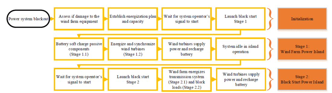
Figure 2 - Flowchart schematizing the main steps of the implemented black start procedure [4]
After Stage 2 is completed and the TSO is also ready, the restoration to the normal operation of the transmission system can be completed by synchronizing the OWF Black Start Power Island (and other possible power islands) with the rest of the power grid. This will complete the restoration procedure and the power system can go back to its normal state.
Overall, this article proposes and compares two configurations for OWFs with integrated energy storage and grid-forming control to perform a black start of the onshore transmission network. The overall control applied to the hybrid power plant is shown and the interoperability of the BESS and WTs achieves a stable operation. Based on the work presented, the capability of OWFs to provide a black start can be applied.
The rest of this article is organized as follows. In Section 2, the modeling and simulation assumptions for this case study are given. Section 3 presents the results of the electromagnetic transient (EMT) studies of the two configurations, where a sensitivity analysis is also carried out to allow this study to be more universal. Finally, the discussion and concluding remarks are given in Section 4.
2. System Modeling
To investigate the interoperability of WTs and BESS with grid-following and grid-forming inverters when providing black start by OWFs, appropriate dynamic models need to be developed. The system used for these studies is shown in Figure 1 and consists of a 420-MW OWF and it is based on the CIGRE WG C4.49 benchmark [16]. This OWF system is chosen as it resembles modern, large OWFs far away from shore that are present in the UK. The BESS with integrated STATCOM capabilities is rated at 50 MW/100 Mvar. The system and converters have been implemented from scratch in PSCAD and they have been modeled from publicly available data in [7, 16].
The BESS and WTs are modeled as controlled voltage sources as shown in Figure 3 to simplify the simulations and focus on the inverter control analysis. Figure 3.a shows the BESS topology modeled, while Figure 3.b shows the structure for the WT. Three-phase, electrical models for both grid-following and grid-forming inverters are developed including their interfaces to the three-phase transmission network EMT solver. These are shown in Figure 3.c for the grid-following converters and in Figure 3.d for the grid-forming and are developed in the synchronous reference frame (dq frame). The analysis is implemented in the EMT software PSCAD.
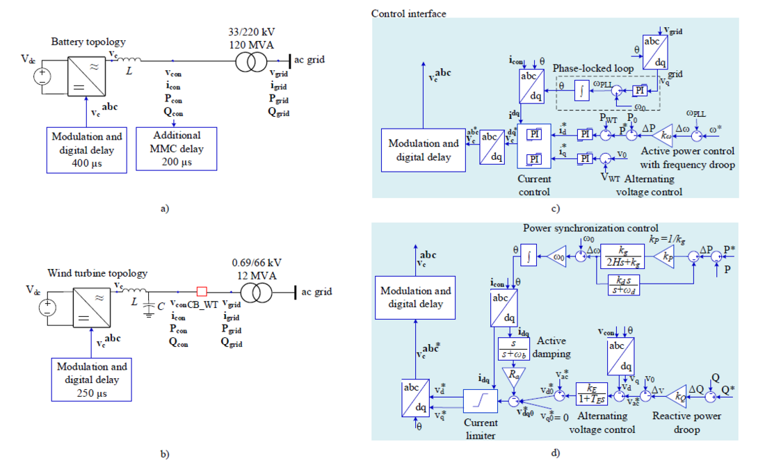
Figure 3 - Converter topology and control interface model
a) Battery converter model; b) wind turbine converter model; c) grid-following control and d) grid-forming control based on power synchronization control
3. Black-Start Configurations and Comparison
As explained, two system configurations are presented and referred to as Configuration 1 and Configuration 2.
3.1. Configuration 1: Grid-Forming Battery and Grid-Following Wind Turbines
The sequence of events shown in the base case for Configuration 1 is summarized in Table 1. Please note that for a real system, each stage of the procedure will take a longer time.
| Event | Stage | Instant [s] |
|---|---|---|
| Initialization, all units shut down | - | 0.0 |
| BESS soft-charge OWF passive network | 1.1 | 0.1-0.5 |
| WT1 is connected | 1.2 | 1.0 |
| WT2 is connected | 1.2 | 1.5 |
| WT3 is connected | 1.2 | 2.0 |
| WT4 is connected | 1.2 | 2.5 |
| WT5 is connected | 1.2 | 3.0 |
| WT6 is connected | 1.2 | 3.5 |
| WT7 is connected | 1.2 | 4.0 |
| Onshore transmission line is connected | 2.1 | 4.5 |
| Onshore transformer T4 is connected | 2.1 | 5.5 |
| 10-MW block load is connected | 2.2 | 10.0 |
| 20-MW block load is connected | 2.2 | 11.5 |
| 50-MW block load is connected | 2.2 | 13.0 |
| Simulation concluded | - | 15.0 |
Figure 4 shows the simulation results for the entire black-start procedure for Configuration 1 from the BESS three-phase instantaneous electrical parameters, i.e., phase-to-ground voltage, current, active, and reactive power. While Figure 5 shows the same electrical parameters for Configuration 1 but they are seen from the first group of aggregated WTs, i.e., WT1. WT1 is chosen as it is also possible to see the impact of the energization of all the other WT groups as WT1 is energized first. To discuss the results, the stages of the black-start procedure will be referred to by the “Stage” numbers defined in Table 1.
3.1.1. Stage 1: Wind Farm Power Island
The black-start procedure starts with the overall hybrid system shutdown together with a part of the onshore transmission network de-energized. Before being able to black start the onshore transmission grid, the OWF+BESS must be powered-up and work in island mode. It is important to state, that since the system will not be connected to the grid, the grid codes do not have to be necessarily respected. The main limitations for the safe operation of the system come from the equipment's withstand capability, which is often more flexible than the grid codes. This advantage is an interesting point for the wind farm operator when working in island mode.
3.1.1.1. Stage 1.1: Soft-Charge of Passive Components
From the state of complete shutdown, the grid-forming converter of the BESS must be the source initiating the procedure. The initial energization of the OWF may start by, for example, a common sequential switching procedure or by soft-charge, i.e., the procedure whereby the BESS converter is controlled to slowly ramp up the voltage to 1 pu while the passive network of the OWF is connected. In OWFs, the presence of submarine cables introduces a significant shunt capacitance to the system, which in turn results in a low natural (resonant) frequency because of other inductive and capacitive components in the system [17, 18]. Furthermore, the presence of transformers also leads to harmonic currents due to their non-linear magnetic characteristics.
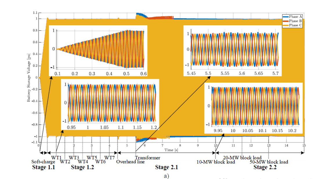
Figure 4 - Black start strategy performed with the offshore wind farm in Configuration 1 (grid-forming battery and grid-following wind turbines) shown from the battery terminals
a) voltage

Figure 4 - Black start strategy performed with the offshore wind farm in Configuration 1 (grid-forming battery and grid-following wind turbines) shown from the battery terminals
b) current
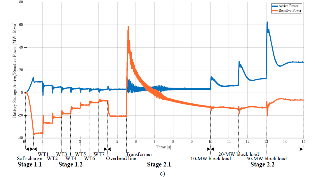
Figure 4 - Black start strategy performed with the offshore wind farm in Configuration 1 (grid-forming battery and grid-following wind turbines) shown from the battery terminals
c) active (blue) and reactive (orange) power
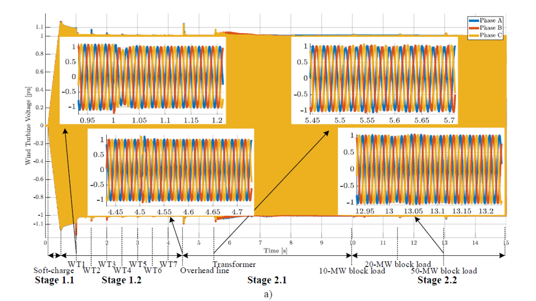
Figure 5 - Black start strategy performed with the offshore wind farm in Configuration 1 (grid-forming battery and grid-following wind turbines) shown from the turbine terminals
a) voltage
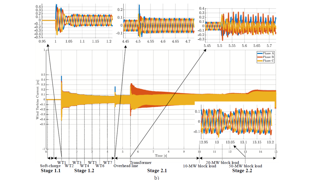
Figure 5 - Black start strategy performed with the offshore wind farm in Configuration 1 (grid-forming battery and grid-following wind turbines) shown from the turbine terminals
b) current
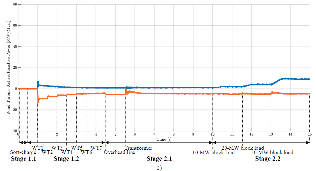
Figure 5 - Black start strategy performed with the offshore wind farm in Configuration 1 (grid-forming battery and grid-following wind turbines) shown from the turbine terminals
c) active (blue) and reactive (orange) power
When initially energized, the transformer may draw a transient inrush current that contains many harmonic components. Therefore, a sustained overvoltage could be excited by one of the harmonic components of the inrush current, if this component is close to the resonant frequency of the power system and depends upon the damping levels. This scenario may cause operational problems, such as equipment failure, and result in the abortion of the black start. To avoid such obstacles, the black-start procedure is begun by the BESS soft-charge, while the passive network of the OWF is connected, including export and array cables, shunt reactors, and transformers T1, T2, and T3.
During the soft charge, all the circuit breakers (CBs) in the blue area of Figure 1 are closed, except for the CB connecting the OWF to the grid, i.e., CB_grid, and the CBs of the WTs, i.e., CB_WT, seen in Figure 3. This stage is referred to as Stage 1.1. Thanks to the selected grid-forming control structure, inspired by power synchronization control (PSC) with virtual synchronous machine (VSM) variation [19], the BESS can soft-charge the system automatically and without needing the reference values on the network to be energized. A novelty of this controller is that it can always operate with zero-power references. The active and reactive power setpoints are processed directly by the grid-forming control loops and the VSM is only in charge of generating compensation references to form the grid with set voltage and frequency, e.g., 1 pu and 50 Hz in this case [20, 21]. The BESS frequency droop is 1.6% and the reactive power droop is 0, i.e., it is de-activated. In the base case in Figure 4.a, the voltage of the BESS is shown, where the soft-charge procedure takes place between 0.1 and 0.5 s. At 0.507 s, the voltage reaches 1.02 pu and then settles at 1.0 pu after 1 cycle. This small overshoot is due to the converter control, where the reference reaches 1 pu and after this, the soft-charge (slow) transient settles to a steady state. Similar behavior is seen in the other electrical quantities. In fact, in Figure 4.b, the BESS current goes at first to 0.35 pu and settles at 0.33 pu. A more marked change is visible in the active power in Figure 4.c, which initially reaches 14 MW and then reduces to 9.6 MW, while the reactive power reaches the peak of 36.9 Mvar and then settles at 35.5 Mvar. The reactive power is the surplus reactive power produced by the cable even though the shunt reactors are connected, and it is absorbed by the BESS. Thus, the BESS at this point is working as an inductive element. The amount of active power that the BESS has to supply initially is relatively low in comparison with the amount of reactive power, which is important to consider when designing the converter rating of the BESS, which could integrate the function of a STATCOM for dynamic reactive power compensation, like in this case. Once the BESS has energized the OWF passive components, the black start proceeds with Stage 1.2, i.e., the connection of WTs.
3.1.1.2. Stage 1.2: Connection and Energization of Wind Turbines
It is assumed that there is enough wind available, and all the WTs are in a favorable position to start, once the black-start procedure must begin. Following the sequence presented in Table 1, the first WT is connected at 1 s. It is simulated that the WT voltage on the WT side of the CB_WT can be synchronized with the grid voltage while the WT is in standalone mode to reduce the switching transient once the CB is closed. The outer loop control of the grid-following WTs consists of a proportional-integral (PI) controller for the active power, where the active power reference is calculated through an active power/frequency droop, set at 5% in the steady state. This setting controls the reference for the direct (d) component of the inner current loop. Moreover, an AC voltage controller sets the reference for the quadrature (q) component of the inner current loop. These settings on the WT controller allow the WTs to participate in the balancing of active and reactive power automatically when sensing the voltage and frequency of the grid, helping the BESS to maintain the power island. The electrical parameters, i.e., phase-to-ground voltage, current, active and reactive power, measured on the WT side of CB_WT are shown in Figure 5. Figure 5.a shows the phase-to-ground voltage, and before 1 s, this voltage is the standalone voltage created for synchronization purposes, so it can be disregarded since the participation of the WT to the black start procedure is simulated after the connection to the system at 1 s. Before the connection of WT1, the standalone voltage is at 1.09 pu, which results in an unperfect synchronization, with Phase B reaching -1.23 pu at 1.001 s. This excess would be obviously unacceptable as it violates the ±10% voltage requirement. However, this connection process of the WTs is only assumed to reduce the computational processing time, as in real life the energization of the WT would also require mechanical dynamics. Therefore, this timeframe must be disregarded. Furthermore, in this simulation, the WTs are aggregated in a single unit for every string, and thus, the transient could be reduced by having a single unit energized at the time. Figure 5.b shows the current of the WT1 that goes from 0 to 0.16 pu in 0.1 s. In Figure 5.c, it is seen that the WT1 generates 3 MW and absorbs 9.2 Mvar in steady-state, sharing the load with the BESS. The following aggregated WTs are connected every 0.5 s and each of them contributes to the load sharing of the system, leaving the BESS to generate 2.8 MW and absorb 7 Mvar at 4.2 s, as seen in Figure 5.c. While the WT1 supplies 0.9 MW and absorbs 4.2 Mvar at 4.2 s, equally as the others. Now that the OWF is fully energized, the OWF+BESS system can move forward to Stage 2, i.e., the actual black start of the transmission network.
3.1.2. Stage 2: Black Start Power Island
Stage 2 of the black start by OWF starts with the closure of CB_grid, which in this simulation takes place at 4.5 s. In this case study, a 50-km overhead line (OHL) and a transformer (T4 in Figure 1) are modeled as the passive components of the transmission system to be black-started. Additionally, three block loads of different ratings, i.e., 10, 20, and 50 MW, are modeled. These different ratings are chosen to test the capability of the system to comply with the grid code requirements [5]. It should be noted that, in this example, the energization of passive components, Stage 2.1, comes first, and it is concluded when the block loads have connected in Stage 2.2. In a real power system, it can be expected that these two sub-stages are not sequential, but interchanged as different lines, transformers, and further equipment leads to loads to be restored.
3.1.2.1. Stage 2.1: Energization of Passive Components
In this case study, a 50-km OHL is energized first. Figure 4.a shows that the BESS voltage is affected minimally by this switching operation, as the highest peak is around 1.04 pu for Phase C, which is within the limits. Furthermore, the voltage waveforms recover from the distortions after 1.5 cycles. Figure 5.a shows instead that the WT voltage surpasses its limit, reaching 1.15 pu at 4.509 s on Phase A. Nevertheless, the voltage waveform settles at the standard 1 pu with a sinusoidal shape in less than 2.5 cycles. The current for both BESS and WTs increases slightly to compensate for the reactive power being exchanged when the OHL is energized. At 5.5 s, the energization of the onshore transformer T4 takes place. Usually, the energization of large transformers like this (240 MVA), can take several seconds to reach a steady state. Therefore, the energization of the transformer T4 is the switching operation, which is simulated the longest, having the next one at 10 s. The energization of the transformer T4 results in both overvoltage and overcurrent for the BESS, as seen in Figure 4.a and Figure 4.b, respectively. This can be expected due to the saturation of the transformer magnetic core and consequent inrush currents. The current of the BESS cannot be limited properly as the BESS current is not explicitly controlled but calculated implicitly based on the voltage and the BESS filter impedance, and then limited. The challenge in current limitation is one of the challenges of not having an explicit current controller in the grid-forming topology. Alternatives for future work will be to implement a grid-forming algorithm with an explicit current controller or add hard limiters to the current grid-forming algorithm. The highest current peak seen in Figure 4.b is on Phase A at 1.16 pu at 5.57 s, with significant distortions. The current lowers and goes back to sinusoidal after 4 s, where it is at 0.16 pu. A transformer is a high inductive load, and Figure 4.c shows the reactive power of the BESS going from 20.6 to 11 Mvar absorbed. As the BESS and the WTs reach a steady state, the following step of the black start can be initiated. As the main purpose of system restoration is to restore consumption, the energization of the block load can be considered the most important stage of the procedure.
3.1.2.2. Stage 2.2: Energization of Block Loads
The grid code requirements for Great Britain require only a minimum of 10-MW block load to be energized. As higher revenue can be achieved by the black-start provider by higher block-load capacity, also 20 and 50 MW block loads are energized in this case study. At 10 s, the 10-MW block load is energized. This switching operation results in a minimal change for the BESS voltage, which is unaltered, as seen in Figure 4.a. The BESS active power goes from 4.3 to 7.1 MW as shown in Figure 4.c, while the WT1 power goes from 4.6 to 4.8 MW, as presented in Figure 4.c, having the remaining load being shared with the other WTs. The connection of the 20-MW and the 50-MW block loads take place at 11.5 and 13 s, respectively. Both events exceed no limits for either BESS or WTs. The energization of block loads from the OWF can ideally continue until the system is completely restored or the full capacity of the OWF is reached (assuming favorable wind conditions).
Overall, the black-start procedure carried out by an OWF with integrated BESS with Configuration 1 could complete the restoration, given that the overvoltage and overcurrent seen when energizing the onshore transmission grid passive components can be solved by means of an optimized controller tuning or additional ancillary equipment such as transformer tap changers and/or pre-insertion resistors or point of wave switching. The OWF is not contributing with high generation in this example, but if the wind is available, it is a possibility. Thus, it will be shown in the case study with Configuration 2.
3.2. Configuration 2: Grid-Forming Battery and Grid-Forming Wind Turbines
The sequence of events shown in the base case for Configuration 2 is summarized in Table 2. Please note that for a real system, each stage of the procedure will take a longer time. It has been chosen to have a 100% grid-forming system in this case study, however, future work may focus on the ratio between grid-forming and grid-following converters in the OWF.
| Event | Stage | Instant [s] |
|---|---|---|
| Initialization, all units shut down | - | 0.0 |
| BESS soft-charge OWF passive network | 1.1 | 0.1-0.5 |
| WT1 is connected | 1.2 | 1.0 |
| WT2 is connected | 1.2 | 3.0 |
| WT3 is connected | 1.2 | 5.0 |
| WT4 is connected | 1.2 | 7.0 |
| WT5 is connected | 1.2 | 9.0 |
| WT6 is connected | 1.2 | 11.0 |
| WT7 is connected | 1.2 | 13.0 |
| Onshore transmission line is connected | 2.1 | 15.0 |
| Onshore transformer T4 is connected | 2.1 | 17.0 |
| 10-MW block load is connected | 2.2 | 27.0 |
| 20-MW block load is connected | 2.2 | 29.0 |
| 50-MW block load is connected | 2.2 | 31.0 |
| Simulation concluded | - | 33.0 |
Due to the slower dynamics of the grid-forming control implemented in this case in all the WTs, this simulation is longer than the one presented with Configuration 1.
As in the previous analysis, Figure 6 shows the entire black-start procedure for Configuration 2 from the BESS electrical parameters. While Figure 7 shows the same electrical parameters for Configuration 2 but is seen from the first group of aggregated WTs, i.e., WT1.
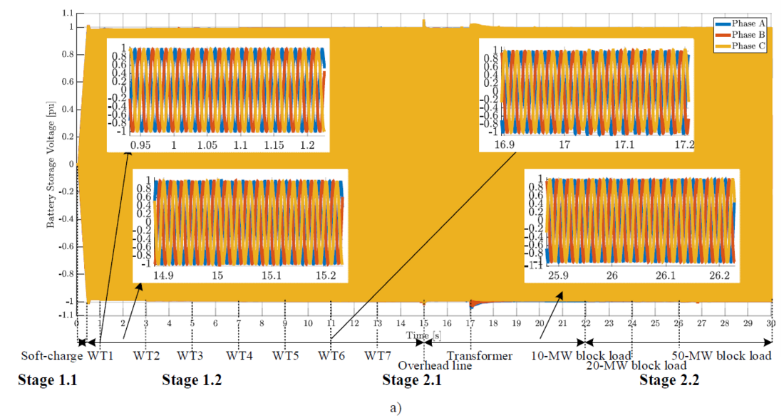
Figure 6 - Black start strategy performed with the offshore wind farm in Configuration 2 (grid-forming battery and grid-forming wind turbines) from the battery terminals
a) voltage
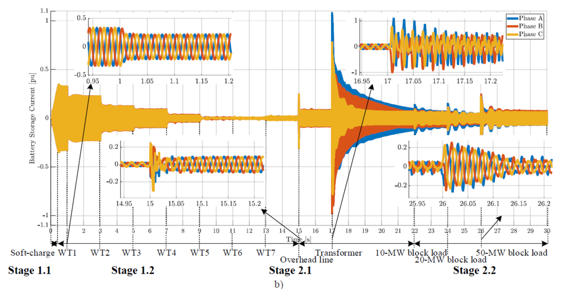
Figure 6 - Black start strategy performed with the offshore wind farm in Configuration 2 (grid-forming battery and grid-forming wind turbines) from the battery terminals
b) current
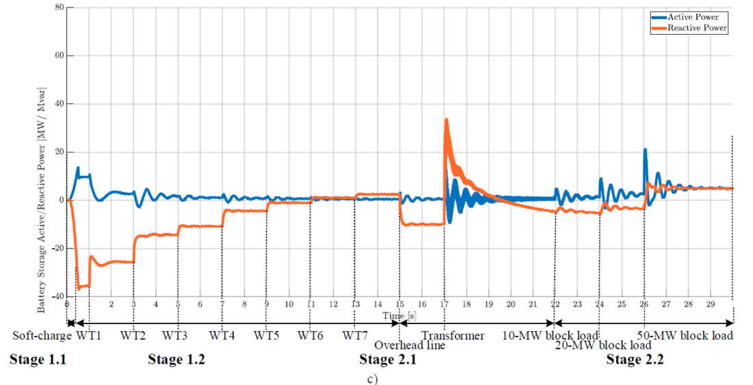
Figure 6 - Black start strategy performed with the offshore wind farm in Configuration 2 (grid-forming battery and grid-forming wind turbines) from the battery terminals
c) active (blue) and reactive (orange) power
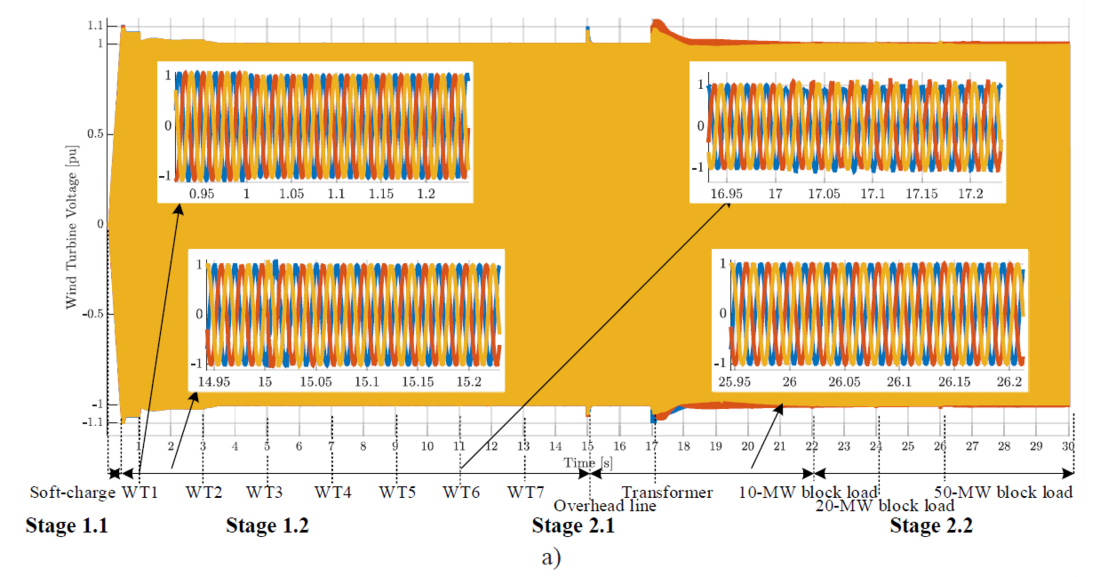
Figure 7 - Black start strategy performed with the offshore wind farm in Configuration 2 (grid-forming battery and grid-forming wind turbines) from the turbine terminals
a) voltage
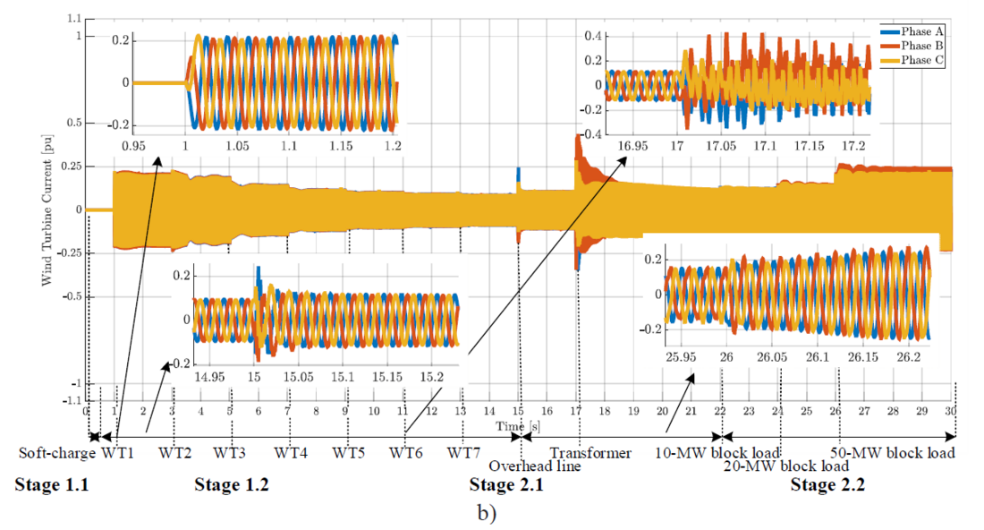
Figure 7 - Black start strategy performed with the offshore wind farm in Configuration 2 (grid-forming battery and grid-forming wind turbines) from the turbine terminals
b) current
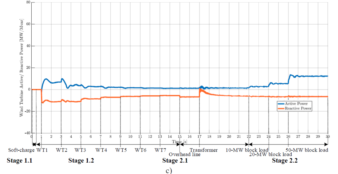
Figure 7 - Black start strategy performed with the offshore wind farm in Configuration 2 (grid-forming battery and grid-forming wind turbines) from the turbine terminals
c) active (blue) and reactive (orange) power
3.2.1. Stage 1: Wind Farm Power Island
3.2.1.1. Stage 1.1: Soft-Charge of Passive Components
In this configuration, it is proposed to start the black-start procedure in the same fashion as in Configuration 1. This consideration is mainly since the black start from the WTs implies the energization of the array cables, which are usually connected as a single string, which is energized at a single instance. It may be challenging for a single WT to energize the array cable, due to the cable reactive loading. Therefore, it has not been included in this analysis but could be investigated as a future work where either the WT capability curve is designed to be able to energize at once the cable or the cable is segmented in smaller parts (which would require a switchgear in each subsection) to allow the first WT to energize two sections and after another WT, and so on. Therefore, the BESS soft-charge procedure is not repeated in this section, as the difference from grid-following to grid-forming control in the WTs is not relevant for this step.
3.2.1.2. Stage 1.1: Connection and Energization of Wind Turbines
After the soft-charge is completed as in the previous configuration, the WTs can be energized. As seen in Figure 6.a, the connection of the WTs has minimal impact on the BESS voltage, which is stable at around 1 pu during the whole procedure. Figure 6.a, shows the same pre-connection voltage as in the previous configuration in Figure 5.a, thus it must be neglected as, once connected, the WT voltage passes from 1.06 to 1.0 pu at 1.02 s. In this configuration, since the controllers of the WTs are in grid-forming mode, and thus react to the frequency and voltage deviations directly, the WTs are also showing a higher contribution of active and reactive power, assuming that they are capable due to favorable wind conditions. This additional wind power generation also implies the recharging of the BESS from the WTs. In fact, Figure 6.b shows the BESS current going from 0.33 to 0.21 pu, and Figure 6.c shows that the BESS active power generation drops from 9.7 to 2.7 MW, while the reactive power goes from -35.6 to -25.7 Mvar at 2.8 s, i.e., when WT1 is energized and in steady state. From the WT1, complementary parameters are presented, as in Figure 7.b the current goes from 0 to 0.23 pu, and Figure 7.c shows active and reactive power going from 0 to 6.8 MW and -11.1 Mvar respectively.
The other WT groups are energized every 2 s, and when all the seven groups are connected and in a steady state at 14.8 s, the BESS only supplies 0.5 MW and 2.5 Mvar as seen in Figure 6.c. Notably, the oscillations connected with the switching of the WTs are reduced with every group of WTs connected. This reduction in oscillations could be due to the characteristics of grid-forming converters that work better in weak grid conditions, which may be the result of many converter-based resources connected to one isolated system [22], as in this case.

3.2.2. Stage 2: Black Start Power Island
Similarly to Configuration 1, once the OWF is working in island mode, Stage 2 can take place together with the actual restoration of the system.
3.2.2.1. Stage 2.1: Energization of Passive Components
At 15 s, the OHL is connected to the OWF system, which results in an overvoltage of 1.05 pu for the BESS, as shown in Figure 6.a, and 1.1 pu for WT1 as seen in Figure 7.a. At 17 s, the connection of the transformer T4 takes place, and this also results in an overvoltage of 1.03 pu for the BESS, as shown in Figure 7.a, and 1.12 pu for WT1 as seen in Figure 8.a. The inrush current reaches 1.09 pu for Phase A the BESS and 0.44 pu for Phase B WT1.
3.2.2.2. Stage 2.2: Energization of Block Loads
The connection of block loads results in higher oscillations in the reactive power than what was seen in Configuration 1, but it is an expected change due to the nature of the grid-forming control, which does not directly control the active power, but instead controls the frequency via an inertial response, reducing its oscillations.
3.3. Black-Start Operation Variations and Sensitivity Analysis
To show a resilient strategy, two variations to the previously presented black-start operation are shown. This is to show that a black start can be performed also when different equipment limitations are present.
3.3.1. Energization of Wind Turbine Transformer Separately from Soft-Charge
In the proposed black-start procedure, it is suggested to connect also the WT transformer to the passive system when shut down and then have the BESS soft charge it. Thus, the energization of the WT transformer separately from the soft-charge is shown here to compare. In both the previous configurations, it has been assumed that it is possible to configure the WT to have first its transformer connected and soft-charged, and then the WT itself can be connected. As an alternative case, it is shown how the BESS can soft charge the system excluding the WT and its transformer. Only one WT and respective transformer are simulated in this case, i.e., not an aggregated array as previously shown. The results of this variation are shown in Figure 8. In this simulation, the soft-charge of the system from the BESS takes place from 0 to 0.5 s. At 0.6 s, the WT transformer is connected, and at 6 s the WT and converter are connected and energized. Figure 8.a shows that the BESS voltage is stable at 1 pu, and Figure 8.b shows that the inrush currents from the transformer are manageable, reaching 0.35 pu on Phase A at the highest. Figure 8.c shows that the connection of the WT transformer results in oscillations that get damped in approximately 1 s, settling at 6.1 MW, therefore not overloading the BESS. In Figure 8.d it can be seen that the reactive load on the BESS during the soft-charge settles at -39.9 Mvar, higher than the -35.5 Mvar, due to the lack of WTs with respective transformers connected to the islanded network in this instance. Therefore, the energization of the WT transformer separately from the soft-charge is feasible but results in a higher reactive loading on the BESS which is already significant. It is shown that the separate energization of the WT transformer is possible, especially since these are 12 MVA transformers, which means that they are not very large This is possible, however, not recommended as the advantages of this procedure are far less than the disadvantages. The inrush currents and possible excitation of the system resonance are one concern, together with the sympathetic interactions, once the second WT transformer has to be energized, as well as the others.
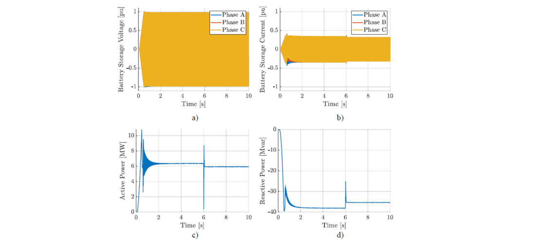
Figure 8 - Energization of wind turbine transformer separately from the soft-charge seen from the battery storage: a) voltage, b) current, c) active power, and d) reactive power
3.3.2. Soft-Charge with Different Time Durations
The energization of the OWF islanded network via soft-charge by the BESS has been shown with a ramp-up from 0.1 to 0.5 s (thus, 0.4 s from 0 to 1 pu) in the base case presented previously. For comparison, three different durations of soft-charge are presented here to analyze the sensitivity of the procedure concerning this different parameter. Two shorter time durations of soft-charge are used, i.e., 0.05 s and 0.2 s. These are shown in Figure 9 and Figure 10 respectively. Both may be possible for the BESS; however, not preferred, as the shorter duration reduces the advantages of implementing it in the first place.
For the soft-charge in 0.05 s, Figure 9.a shows that the BESS voltage reaches 1.1 pu at 0.16 s, to then settle at 1 pu at 0.3 s. While Figure 9.b shows that the current reaches 0.78 pu on Phase B to then settle at 0.33 pu. Figure 9.c shows that the active power reaches the high value of 44 MW (14 MW in the base case) to then settle at 6 MW. Also, the reactive power has a high overshoot, reaching -49 Mvar at 0.24 s to then settle at -35.5 Mvar. Figure 10.a shows the BESS voltage when the soft-charge duration is 0.2 s, and it results as well in an overvoltage at 1.1 pu. Figure 10.b shows how the BESS current reaches 0.6 pu at 0.31 s.
Figure 10.c presents the overshoot of the active power at 27 MW, while Figure 10.d shows the reactive power peak at -45 Mvar. All in all, the transition is seen as softer due to the longer duration, as expected.
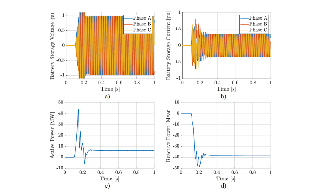
Figure 9 - Soft-charge in 0.05 s: a) voltage, b) current, c) active power, and d) reactive power

Figure 10 - Soft-charge in 0.2 s: a) voltage, b) current, c) active power, and d) reactive power
To avoid overvoltage, a soft charge duration of 0.4 s shown in the base case is sufficient. For comparison, an even longer duration of 0.8 s is shown in Figure 11. Figure 11.a shows the BESS voltage that goes from 0 to 1 pu, while Figure 11.b shows similar results for the current. Figure 11.c and Figure 11.d show the active and reactive power respectively, which result in the smallest overshoot seen in the active power at 8.5 MW before settling at 6 MW.
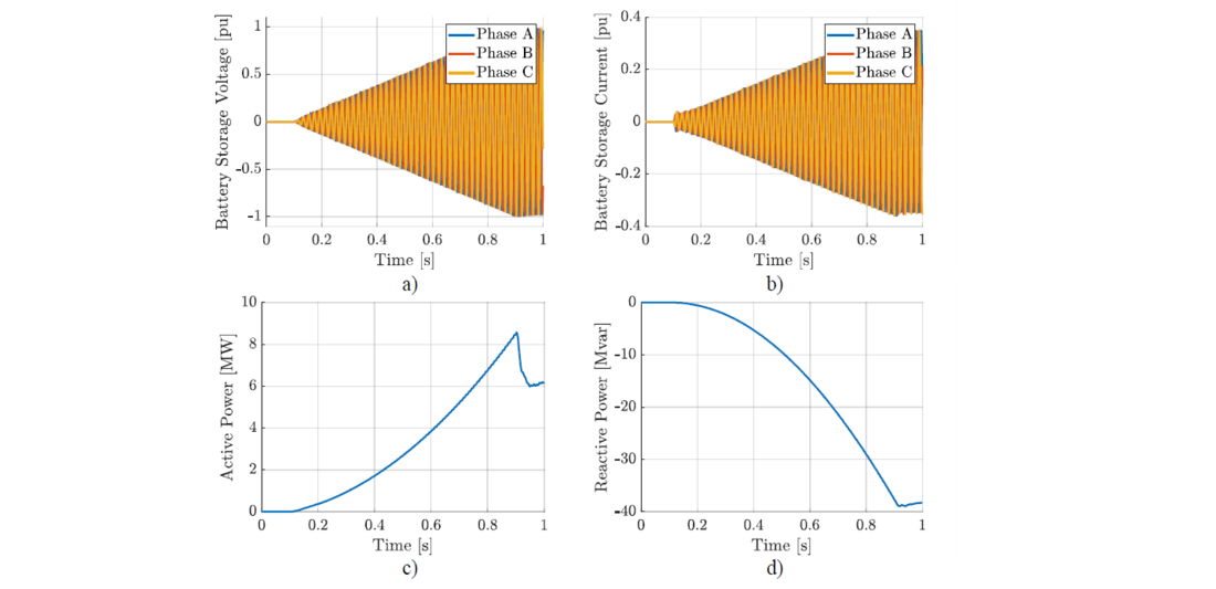
Figure 11 - Soft charge in 0.8 s: a) voltage, b) current, c) active power, and d) reactive power
4. Conclusion and Future Work
An OWF system has been designed to perform a black start using an integrated ESS with only power electronic-based components. For the black start, power electronic converters must be able to operate in island mode, and regulate the system frequency and voltage, with at least one grid-forming unit. This capability to work without a pre-existent grid is in opposition to the well-known grid-following operation in which renewable-based resources are controlled to extract the maximum available power. The black start capability of the proposed control system is possible through the integration of a grid-forming BESS, which performs the initial system energization and boosts the availability to perform a black start even when there is no wind.
The challenge of a hybrid power plant like an OWF+BESS system with multiple converters working in island mode, where transient phenomena are triggered when hard switching to connect new parts of the system has been presented. The interoperability of the system in such conditions is recognized as a challenge and a solution is proposed in terms of two different configurations that can achieve this procedure, i.e., Configuration 1 consisting of a grid-forming BESS integrated into an OWF with grid-following WTs and Configuration 2 consisting of both grid-forming BESS and WTs. These ensure that the black start procedure can be carried out completely with the connection of block loads up to 50 MW.
The proposed configurations are applied to a case study where a 420-MW OWF with integrated BESS black starts a transmission system made of an OHL, a transformer, and three block loads. The modeling of this case study is presented to illustrate the proposed control system operation and simulation results are presented to validate the proposal. Also, a configuration variation and sensitivity analysis has been performed to demonstrate the stability of the black start procedure despite varying parameters. The selection of the most suitable configuration for the OWF developer to implement is left as future work, as both configurations can complete a black start. Further controller design studies may achieve higher capabilities for the system, where grid-forming control may be able to perform in weaker systems than grid-following control.
The results show that an OWF can be controlled to perform a black start without relying on additional diesel generators, to avoid its physical footprint as backup equipment and releasing CO2 emissions. The grid-forming BESS can soft-charge passive components and energize the grid-following/grid-forming WTs in an isolated system. Since this energization is independent of active power, it can be performed even for varying wind power scenarios. Once the WTs are started, the actual black start of the transmission grid can take place and, energizing up to 50 MW block loads, the black-start process is completed. For future work, the operation used for Configuration 2 can be analyzed when starting the energization process from the WTs, applying the BESS only if support is necessary. A few other aspects are mentioned for future work, such as the analysis of ancillary support from point of wave switching/ pre-insertion resistor for the CBs. An important exercise to design a real system will be to size the BESS and take into account the variation of wind generation against the block load size. Thus, it is recommended for future work. Another aspect that could be investigated could be the application of grid-forming algorithms with an explicit current controller, to allow better regulation of the current in the converters, since they do not possess overcurrent capabilities like synchronous machines. Further aspects considered for future work are the stability analysis of the system for both small and large signal by means of other methods than EMT simulations, for example, state-space and/or frequency domain methods. These studies will allow the analysis of more scenarios given the lower time of execution compared to EMT studies. Furthermore, the analysis of the origin for possible instability could be investigated. For example, converter control interactions could be studied and guidelines on converter control bandwidth with respect to specific passive components of the system could be detailed. Moreover, the short-circuit power is also recognized as a challenge in a power electronic-based system such as the OWF+BESS, especially working in islanded mode as it happens with a black start. Future work may focus on the system challenges in system stability and in system protection.
Having a real OWF project, the worst-case inrush currents during the black-start procedure, especially while energizing large transformers, can be estimated, and compared against capability curves and current limits of the active equipment. This design exercise will lead to defining the optimal procedure to reduce the loading on such equipment based on reduced generator terminal voltage, robust controller tuning and regulation of the reactive power compensation, and overall, the optimal sizing of the grid-forming BESS and WTs.
Acknowledgment
This article is the outcome of a Ph.D. project in collaboration with Ørsted and Aalborg University, Denmark. The authors would like to acknowledge the funding received from Innovation Fund Denmark. The authors would like to acknowledge the discussions and inputs from Troels Stybe Sørensen and M. Kazem Bakhshizadeh (Ørsted).
References
- BloombergNEF, "Annual Offshore Wind Installations to Triple This Decade," 16 February 2021. [Online] [Accessed 23 November 2022].
- D. Ramasubramanian, W. Baker, V. Singhi, S. Uppalapati and E. Farantatos, "Distribution Feeder and Critical Load Blackstart and Restoration using Inverter Based Resources," CIGRE Science and Engineering, vol. 26, no. November, pp. 1-20, 2022.
- J. Rocabert, A. Luna, F. Blaabjerg and P. Rodriguez, "Control of Power Converters in AC Microgrids," IEEE Transactions on Power Electronics, vol. 27, no. 11, pp. 4734-4749, 2012.
- D. Pagnani, Ł. Kocewiak, J. Hjerrild, F. Blaabjerg and C. L. Bak, "Control Principles for Island Operation and Black Start by Offshore Wind Farms integrating Grid-Forming Converters," in 2022 24th European Conference on Power Electronics and Applications (EPE'22 ECCE Europe), pp. 1-11, 2022.
- National Grid Electricity System Operator, "Appendix 1 - Technical Requirements and Assessment Criteria for the ESR Wind Tender 2022," Warwick, United Kingdom, 2022.
- D. Pagnani, Ł. Kocewiak, J. Hjerrild, F. Blaabjerg and C. L. Bak, "Overview of Black Start Provision by Offshore Wind Farms," in 46th Annual Conference of the IEEE Industrial Electronics Society, Singapore, pp. 1-6, 2020.
- S. K. Chaudhary, R. Teodorescu, J. R. Svensson, Ł. Kocewiak, P. Johnson and B. Berggren, "Black Start Service from Offshore Wind Power Plant using IBESS," in 2021 IEEE Madrid PowerTech, online, pp. 1-6, 2021.
- W. Briceno-Vicente, "Grid Code Requirements in the UK for the Connection of BESS in Wind Systems," CIGRE Science and Engineering, vol. 25, no. June 2022, pp. 1-24, 2022.
- S. Cherevatskiy, S. Sproul, S. Zabihi, R. Korte, H. Klingenberg, B. Buchholz and A. Oudalov, "Grid Forming Energy Storage System Addresses Challenges of Grids with High Penetration of Renewables (A Case Study)," in CIGRE Paris Session 2020, Online, pp. 1-13, 2020.
- S. Hadavi, S. Phu Me, B. Bahrani, M. Fard and A. Zadeh, "Virtual Synchronous Generator versus Synchronous Condenser: An Electromagnetic Transient Simulation-based Comparison," CIGRE Science and Engineering, vol. 24, no. February 2022, pp. 1-19, 2022.
- A. Roscoe, T. Knueppel, R. Da Silva, P. Brogan, I. Gutierrez, D. Elliott and J.-C. Perez Campion, "Response of a Grid Forming Wind Farm to System Events, and the Impact of External and Internal Damping," IET Renewable Power Generation, vol. 14, no. 19, pp. 3908-3917, 2020.
- NREL, "Landmark Demonstration Shows How Common Wind Turbine Can Provide Fundamental Grid Stability," NREL, 14 January 2022. [Online] [Accessed 4 November 2022].
- J. Martínez-Turégano, S. Añó‐Villalba, S. Bernal-Pérez and R. Blasco‐Gimenez, "Small-Signal Stability and Fault Performance of Mixed Grid-Forming and Grid-Following Offshore Wind Power Plants connected to a HVDC-Diode Rectifier," IET Renewable Power Generation, vol. 14, no. 12, pp. 1-10, 2020.
- B. Badrzadeh, E. Farahani, N. Modi, N. Crooks and D. Ryan, "Sustained Islanding Operation of a Normally Interconnected Power System with a High Share of Inverter-based Resources – South Australian Experience," CIGRE Science and Engineering, vol. 21, no. June 2021, pp. 170-179, 2021.
- D. Pagnani, Ł. Kocewiak, J. Hjerrild, F. Blaabjerg and C. L. Bak, "Integrating Black Start Capabilities into Offshore Wind Farms by Grid-Forming Batteries," IET Renewable Power Generation, vol. Early Access, no. Early Access, pp. 1-12, 2022.
- Ł. Kocewiak, R. Blasco-Giménez, C. Buchhagen, J. B. Kwon, Y. Sun, A. Svchwanka Trevisan, M. Larsson and X. Wang, "Overview, Status and Outline of Stability Analysis in Converter-based Power Systems," in 19th Wind Integration Workshop, Online, pp. 1-10, 2020.
- C. Hardt, D. Premm, P. Mayer, F. Mosallat and S. Goyal, "Practical Experience with Mitigation of Sub-synchronous Control Interaction in Power Systems with Low System Strength," CIGRE Science and Engineering, vol. 21, no. June 2021, pp. 5-13, 2021.
- A. Nikkila, A. Kuusela, A. Harjula, T. Rauhala and L. Haarla, "Ferroresonance and Subsequent Sustained Parallel Resonance Occurrence During Power System Restoration: Analyses for System Operation," CIGRE Science and Engineering, vol. 21, no. June 2021, pp. 141-169, 2021.
- L. Harnefors, M. Hinkkanen, U. Riaz, F. M. M. Rahman and L. Zhang, "Robust Analytic Design of Power-Synchronization Control," IEEE Transactions on Industrial Electronics, vol. 66, no. 8, pp. 5810-5819, 2019.
- P. Kundur, Power System Stability and Control, McGraw-Hill Education, 1994.
- F. Mandrile, "Next Generation Inverters Equipped with Virtual Synchronous Compensators for Grid Services and Grid Support," Politecnico di Torino, Ph.D. Series, Torino, 2021.
- F. Zhao, X. Wang, Z. Zhou, Ł. Kocewiak and J. Svensson, "Comparative Study of Battery-based STATCOM in Grid-Following and Grid-Forming Modes for Stabilization of Offshore Wind Power Plant," Electric Power Systems Research, vol. 212, no. 108449, pp. 1-12, 2022.
- A. Roscoe, T. Knueppel, R. Da silva, P. Brogan, I. Gutierrez, J. Perez Campion, D. Elliott and P. Crolla, "Practical Experience of Providing Enhanced Grid Forming Services from an Onshore Wind Park," in 19th Wind Integration Workshop, Online, pp. 1-6, 2020.
Biographies
Daniela Pagnani was born in Caracas, Venezuela, in 1995. She obtained a B.Sc. in industrial engineering from the University of Cassino, Italy, in 2017, and an M.Sc. in electrical power systems and high voltage engineering from Aalborg University, Denmark, in 2019. She is currently finalizing a Ph.D. degree at Aalborg University, in collaboration with Ørsted, Fredericia, Denmark, as the industrial partner. Since 2021, she is the Chair of the Steering Committee of CIGRE Next Generation Network Denmark. Her special fields of interest include power system analysis, renewable energy transition, grid-connected converters, black start, and island operation.
Łukasz Kocewiak received the B.Sc. and M.Sc. degrees in electrical engineering from the Warsaw University of Technology, Warsaw, Poland, in 2007, and the Ph.D. degree from Aalborg University, Aalborg, Denmark, in 2012. He is currently a Research and Development Manager and a Lead Power System Specialist on the development of electrical infrastructure in large offshore wind power plants with Ørsted, Fredericia, Denmark. He has authored or co-authored 100+ publications. His current research interests include harmonics, stability, and nonlinear dynamics in power electronics and power systems. He is a member of various working groups and activities within CIGRE and IEC.
Jesper Hjerrild received the M.Sc. and Ph.D. degrees in electrical engineering from the Technical University of Denmark, Lyngby, Denmark, in 1999 and 2002, respectively. He is currently with Ørsted, Fredericia, Denmark, where he is a Senior Lead Power System Specialist in the Electrical System Design and Grid Integration department. His research interests include electrical power systems in general, involving a variety of technical disciplines of power systems including wind power and power system power flow, control, stability, and harmonics. Furthermore, he also works with designing and optimizing wind farms and integrating them into the power system.
Frede Blaabjerg (S’86–M’88–SM’97–F’03) is a Full Professor of power electronics and drives at Aalborg University since 1998. Since 2017, he became a Villum Investigator. He is honoris causa at Politehnica University of Timișoara, Romania, and Tallinn Technical University, Estonia. His current research interests include power electronics and its applications such as in wind turbines, PV systems, reliability, harmonics, and adjustable speed drives. He has published more than 600 journal papers in the fields of power electronics and its applications. He is the co-author of four monographs and editor of ten books on power electronics and its applications.
Claus Leth Bak is a Full Professor at the Department of Energy at Aalborg University, Denmark. He obtained his Ph.D. degree in 2015 and is the author of 400+ publications. He is the Chair of the Danish CIGRE National Committee, a former member of the CIGRE Technical Council (2020-2022), and a member of CIGRE SC C4 AG1 and D1. He received DPSP 2014 and PEDG 2016 Best Paper Awards. He was awarded the CIGRE Distinguished member award (2020) and the CIGRE TC award (2020). He serves as Head of the Energy Ph.D. Program and as Head of Section for Electric Power Systems and Microgrids.
Ramón Blasco-Giménez obtained a BEng. degree from the Universitat Politècnica de València, Valencia, Spain, in 1992, and a Ph.D. degree from the University of Nottingham, U.K., in 1996. He is currently a Full Professor and the Head of the Research Institute on Automatics and Industrial Informatics (Ai2). His research interests include control of motor drives, wind power generation, offshore wind farms and grid integration of renewable energy, and HVDC diode rectifiers. He has been a co-recipient of the 2005 IEEE Transactions on Industrial Electronics Best Paper Award. He is a member of various working groups and activities within CIGRE.
Jaime Martínez-Turégano received an M.Sc. degree in electronics and automatic control engineering from the Universitat Politècnica de València, Valencia, Spain, in 2014, and a Ph.D. degree from the Institute of Control and Industrial Informatics in 2022. From 2015 to 2016, he worked as a control software development and validation engineer for the aerospace sector. His research interests include grid-forming control, control of wind power plants, black start, and HVDC diode rectifiers.