Security Criterion for Distance Zone 1 Applications in High SIR Systems With CCVTs – Part 1: Transient Errors
Authors
B. KASZTENNY, R. CHOWDHURY - Schweitzer Engineering Laboratories, Inc., USA

Summary
In this two-part paper, we present a practical engineering procedure for verifying security of a directly tripping distance Zone 1 protection element in applications to lines with high source-to-line impedance ratios. In this part, we consider transient security errors caused by capacitively coupled voltage transformers. Part 2 considers steady-state errors caused by instrument transformer errors, line impedance errors, ground potential rise, and mutual coupling.
While factors that impact the Zone 1 security are generally known, there are no practical procedures for verifying the security of Zone 1 applications based on simple engineering calculations that use readily available data. This paper closes this gap by proposing how to quantify the impact of key interfering factors and showing how to verify the Zone 1 security.
The presented Zone 1 security criterion is intended to guide practitioners by either confirming the protection security of the preferred Zone 1 application or directing them to change application parameters, such as reducing the reach setting or adding a time delay.
Part 2 available on this page
Keywords
Capacitive voltage transformer, distance protection, source impedance ratio, transient overreach,Zone 1
1. Introduction
An underreaching directly tripping Zone 1 distance element is a valuable option for line protection. It operates without reliance on a protection channel. For lines without a protection channel, it provides primary protection. For lines with a protection channel – available to most lines today – it provides redundancy for communications-assisted protection schemes, such as directional comparison schemes and line current differential schemes. The directly tripping Zone 1 element may also reduce the protection operating time, especially if the protection channel is relatively slow while the line is relatively long and the local terminal is relatively strong.
For a Zone 1 element to trip without communications assistance, it must be secure. Directional supervision built into the Zone 1 elements ensures directional integrity for reverse faults. Therefore, from the application perspective, the Zone 1 security is only concerned with overreaching (tripping for forward out-of-zone faults). We classify the Zone 1 overreach as either a transient overreach (focus of Part 1) or a persistent overreach (focus of Part 2 [1]). These two types have different causes and solutions [2]. Both Part 1 and Part 2 are available together as [3].
A transient overreach is caused by transient components in the relay voltages and currents. Even though transients in any of the distance element voltages and currents play a role, the capacitively coupled voltage transformer (CCVT) transients are by far the most consequential. Protective relays provide effective filtering for both high-frequency oscillatory components in voltages and currents, as well as for the decaying direct current (dc) component in currents. These interfering signal components have a frequency spectrum that is far from the fundamental frequency, allowing the relay to effectively suppress them. The CCVT transients, in contrast, may have large magnitudes, and their frequency spectrum is relatively close to the fundamental frequency [4]. As a result, it is challenging to suppress the CCVT transients, especially if a fast Zone 1 operation is desired.
Filtering and other advanced security measures built into distance relays can address transient overreach. A user can further improve Zone 1 transient overreach by adding a time delay or by shortening the reach.
High source-to-line impedance ratio (SIR) applications dramatically exacerbate the danger of Zone 1 overreach – both transient and persistent. When the SIR is high, the relay voltage for faults at the remote bus is low (so is the loop voltage of a distance element). The distance element operating signal (IZ – V) is even smaller [2]. When a protection operating signal is small, even small errors in voltages and currents may impact security.
The impact of the combination of the CCVT transients and a high SIR on the security of distance Zone 1 protection elements is well understood [2] [4]. However, because a combination of several factors affects the Zone 1 security, including the Zone 1 element design and the CCVT transient response, no accurate and practical criterion exists for verifying the security of the Zone 1 applications. The classification of transmission lines into short, medium, and long included in the IEEE Std C37.113-2015 (Line Protection Guide) [5] omits many of the practical dimensions of the impact of the SIR on Zone 1 applications, making it too simplistic to be a practical security criterion. Additionally, the Line Protection Guide [5] does not provide application recommendations that would depend on the SIR or the line length. Protective relay manufacturers routinely claim a 5 percent Zone 1 transient overreach for an SIR as high as 30 and any CCVT make and model. Sometimes these claims are vague and do not specify if the 5 percent overreach applies to CCVTs or magnetic VTs. Also, these claims are known to be challenged by reports of occasional Zone 1 misoperations.
Consequently, a practitioner may be left with a void and uncertainty regarding the security of a Zone 1 application. Reference [2] provides an in-depth description and analysis of the relevant factors but does not include specific methods for engineering a particular application. This paper builds on [2] to provide simple and practical methods that quantify the relevant factors to verify the Zone 1 security in high SIR applications. Both the transient overreach and the persistent overreach criteria start with these input data:
- Worst-case SIR values for phase and ground faults obtained from a short-circuit program.
- Intended Zone 1 reach setting.
The Zone 1 security criterion we present in this paper for transient overreach due to CCVTs is based on the following data:
- The Zone 1 operating time published by the relay manufacturer.
- The Zone 1 intentional time delay, if any.
- The CCVT transient response envelope available from the CCVT manufacturer.
The transient overreach security criterion allows the practitioners to select a combination of the reach setting, CCVT type, and intentional time delay (preferably 0) that ensures a secure Zone 1 application.
This part of the paper is organized as follows. Section 2 explains the Zone 1 operating signal and shows how to use it when analyzing the impact of errors on Zone 1 security. Section 3 derives the transient security criterion for Zone 1 applications in high SIR systems with CCVTs. Section 4 presents a step-by-step procedure of evaluating Zone 1 security with the CCVT transients and illustrates it with examples. Section 5 proposes a new format that relay manufacturers can use to specify the Zone 1 security in relation to the CCVT transients.
2. Zone 1 Operating Signal and SIR
2.1. Zone 1 Operating Signal
The distance element operating signal (IZ – V) is convenient when explaining and analyzing Zone 1 security issues [2]. In the IZ – V term, which is a voltage term, I is the loop current, V is the loop voltage, and Z is the impedance corresponding to the reach point of the Zone 1 element. The IZ – V operating signal applies universally to all distance element implementations. It also applies to both the mho and reactance operating characteristics. A Zone 1 element operates based on a phase comparison of the IZ – V operating signal and the selected polarizing signal.
The CCVT transients and other voltage errors do not impact the Zone 1 polarizing signal because the polarizing signal is derived by using memory (memory-polarized mho elements) or current (reactance elements). It is only the IZ – V operating signal that is impacted by both the transient and persistent errors in the loop voltage and current and the persistent errors in the reach impedance. This observation allows us to develop a common Zone 1 security criterion for both the mho and the quadrilateral distance elements.
A Zone 1 element in a distance relay measures the voltages and currents and effectively acts on the IZ – V operating signal. We can think of the measured IZ – V operating signal as comprising the true IZ – V operating signal and an error. The IZ – V operating signal is effectively a voltage, so we can write:
(1)
VERROR is the error in the loop voltage (V) or in the IZ term or both. The error in the IZ term results from the error in the loop current (I) or the reach impedance (Z).
Equation (1) provides a high-level concept. Different relays apply different low-pass or band-pass filtering before obtaining the IZ – V operating signal. When processing the IZ – V operating signal, some distance relays use phasors and phase comparators, while other relays use instantaneous values and coincidence timing. Some relays use the IZ – V term explicitly, while other relays perform equivalent calculations, such as the m-calculation, the polarized apparent impedance calculations, or the torque calculations [6]. Conceptually, however, we can analyze all these relays by looking at the true IZ – V operating signal in relation to the error signal, VERROR.
The main point of (1) is that as long as the magnitude of the error (VERROR) is small compared to that of the true IZ – V operating signal, the measured IZ – V operating signal has the correct polarity or phase angle relationship relative to the polarizing signal, and the Zone 1 element operates correctly. Therefore, we can conceptualize the Zone 1 security criterion as follows:
(2)
where | | stands for magnitude.
Condition (2) allows us to simplify the analysis by neglecting the relative polarities of the true IZ – V operating signal and the error signal. These two signals can effectively add or subtract. When the error signal has the same polarity as the true operating signal, it increases the measured operating signal and the Zone 1 element will not overreach. When the error signal has the opposite polarity as the true operating signal, it decreases the measured operating signal; if the measured operating signal polarity is inverted, the Zone 1 element overreaches. By requiring that the error signal be smaller than the true operating signal, we ensure that the measured operating signal polarity will not be inverted and the element will not overreach.
The true IZ – V operating signal in per-unit values of the loop nominal voltage depends on the SIR and the Zone 1 per-unit reach (m1), as shown in (3) [2]:
(3)
where m is the per-unit fault location.
2.2. Source-to-Line Impedance Ratio
Recently, a common agreement emerged that the SIR is based on the per-unit relay voltage magnitude for a metallic remote bus fault instead of the line and system impedances [2] [7] [8]. This improved SIR definition is consistent with thinking of the SIR as a parameter in a voltage divider that represents the simplified faulted-loop circuit. In this concept, the SIR determines how high or low the relay voltage is for a fault at the end of the protected line. This recent understanding of the SIR makes (3) exact.
As a result of linking the SIR to the relay voltage for a remote bus fault, two SIR values must be considered: SIRLL and SIRLG, for phase and ground faults, respectively. SIRLL is for evaluating the security of the Zone 1 phase element. SIRLG is for evaluating the security of the Zone 1 ground element. SIRLG is often lower than SIRLL because of the grounding paths presented by network transformers. For simplicity, we use a single variable SIR in this paper and avoid differentiating between the phase and ground elements, unless necessary. In addition to experiencing different SIR values, the Zone 1 phase and ground elements may use different reach settings. As a result, the security of the Zone 1 phase and ground elements must be verified separately. For simplicity, we use a single variable for Zone 1 reach (m1) and avoid differentiating between the phase and ground elements, unless necessary.
As expected, (3) shows us that the operating signal is zero when the fault is located at the reach point (m = m1). When the fault moves away from the reach point, either inside Zone 1 (m < m1, internal fault) or outside Zone 1 (m > m1, external fault), the operating signal increases proportionally to the difference between m and m1.
We are concerned with the Zone 1 security (an overreach for a remote bus fault), and therefore, we consider the IZ – V value not for any fault location (m) but for the closest external fault in the Zone 1 direction, i.e., for a remote bus fault (m = 1). Inserting m = 1 in (3) gives us:
(4)
Because Zone 1 is set to underreach (m1 < 1), we can remove the absolute sign in (4). Equation (4) allows us to account for the SIR: the weaker the system, the smaller the IZ – V operating signal and the greater the security problem. Equation (4) also allows us to account for the Zone 1 reach, m1: the longer the reach, the smaller the IZ – V operating signal and the greater the security problem.
We combine (4) and (2) and obtain a general Zone 1 security criterion as follows:
(5)
Condition (5) shows a Zone 1 margin of 1 – m1.
3. Transient Security Criterion
Because distance relays filter high-frequency transients in voltages and currents, as well as decaying dc components in the current, we can focus on the CCVT transients only.
3.1. CCVT Transients
During fault conditions, a significant transient component is present in the CCVT secondary voltage. That transient is proportional to the change in voltage between the pre-fault and fault states. In high SIR applications, the voltage changes from the pre-fault nominal value to a very small value. Figure 1 through Figure 3 show the CCVT secondary voltage for sample CCVTs. Each figure shows a set of waveforms for bolted faults at the CCVT location that occur at different points on wave. Because the true ratio voltage during these faults is zero, the secondary voltage represents the highest possible CCVT transient. We can see that the magnitude, character, and duration of the CCVT transients depend on the CCVT type and point on wave. Reference [4] provides more information on the CCVT transients in relation to the impact of the CCVT parameters and burden, a transient damping device (if present), and the ferroresonance suppression circuit.
In theory, the voltage signal that appears after t = 0 in Figure 1 through Figure 3 is the VERROR component in (5). However, we would face several challenges if we were to apply (5) to this VERROR.
Consider these points:
- The CCVT transient is not a number but a time series, and its waveform depends on the fault point on wave.
- Distance relays apply filtering and reduce the CCVT transients in the loop voltage.
- Different CCVTs output very different transients.
- The transient response cannot be easily determined from the CCVT nameplate data.
We solve these challenges in the following subsections.
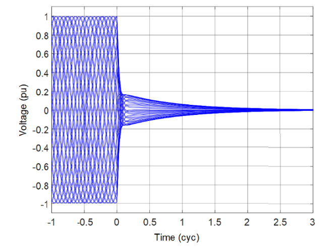
Figure 1 - CCVT transients: exponential decay response
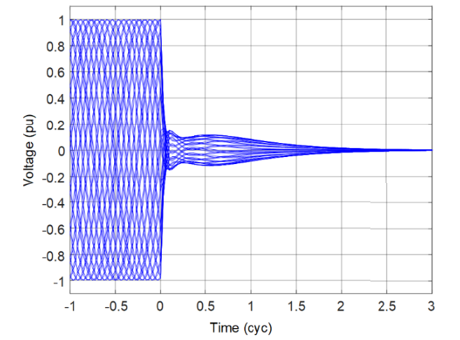
Figure 2 - CCVT transients: oscillatory response
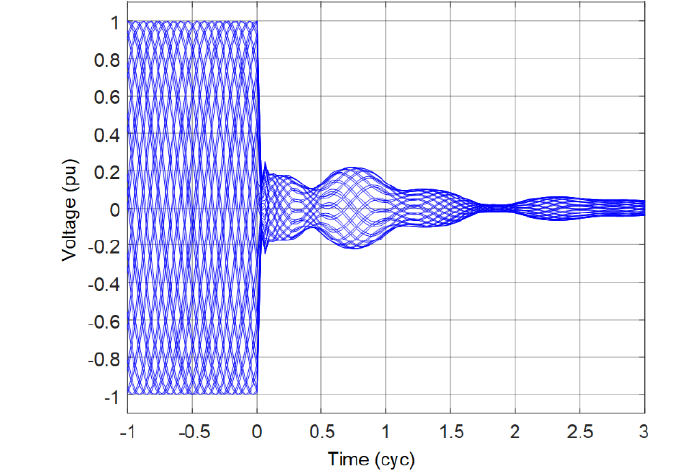
Figure 3 - CCVT transients: a case of large and prolonged transients

Figure 4 - Sample CCVT transient and the relay data window at the time of Zone 1 operation
3.2. Quantifying CCVT Transients With Respect to Time
Figure 4 shows a sample CCVT transient and a data window of a distance relay that operates in TOP milliseconds following the fault inception. We assume a microprocessor-based relay and show its finite impulse response (FIR) filter window. The window length is W cycles (W = 1 cycle, for example).
It is justified to assume that if the Zone 1 element overreaches for a fault just beyond its reach point, the time of misoperation would be similar to the time of correct operation for a fault just short of the reach point. This key observation allows us to use the Zone 1 operating time as the estimate of effective internal delay that the Zone 1 element design applies for security. The longer the operating time for an internal fault close to the reach point, the more secure the Zone 1 element is. If that element misoperates for a fault beyond the reach point, it would do so after a similar time.
We introduce the following variable:
TOP is the Zone 1 operating time for the SIR of interest and the farthest fault location for which the manufacturer publishes the operating time. If the manufacturer publishes separate curves for magnetic VTs and CCVTs, use the latter to obtain TOP.
When the Zone 1 element operates in TOP milliseconds, the relay filters are filled with data that stretch between TOP – W and TOP.
Assume further that the user can intentionally delay the Zone 1 element by using a pickup timer of TD milliseconds. Of course, TD could be zero.
Under the above rational assumptions, we observe that, at the time of a possible Zone 1 overreach for an external fault, the filters are filled with data that stretch between TOP + TD and TOP + TD – W. This means that the CCVT transients between the fault inception (t = 0) and t = TOP + TD – W have no or little impact on the Zone 1 security.
As a result, we replace the voltage error in (5) with the CCVT transient error (ECCVT) starting from t = TOP + TD – W onward:
(6)
Criterion (6) captures the expected relationship between Zone 1 security and the intentional time delay (adding delay subjects the Zone 1 element to a smaller CCVT error because that error decays with time). Criterion (6) also captures the expected relationship between the Zone 1 security and the inherent speed of the Zone 1 element (slower Zone 1 designs will typically have less problems with the CCVT transients).
Furthermore, (6) ensures coherence between the effective internal time delay (TOP) and the additional time delay the user may apply (TD). Criterion (6) uses the sum of the two delays (TOP + TD), making it irrelevant how the delay is achieved (a slower Zone 1 element design or an additional time delay applied by the user).
The window length (W) may be challenging to obtain. Some Zone 1 element designs use both fullcycle and half-cycle windows. Some designs use variable data windows. Yet other designs use finite response filters to prefilter the voltage, current, or both. Obtaining and using these design details from the relay manufacturer would not be practical.
We propose using W = 1 cycle as a reasonable estimate. This approximation is justified by the fact that if the Zone 1 element overreaches because of the CCVT transients, it does it relatively late (after 1 to 1.5 cycles). If the relay uses a variable data window, that window will have already grown in length to one cycle by that time. If the relay uses a half-cycle window, using W = 1 cycle is a conservative and secure approximation because the CCVT transients subside over time, and therefore a full cycle window would have higher transients inside of it than a half-cycle window.
Therefore, we substitute W = 1 cycle in (6) and write:
(7)
Normally, a Zone 1 element would not operate faster than in 1.5 cycles for high SIR values and faults near the end of the zone (i.e., TOP > 1.5 cycles). Therefore, TOP – 1 cycle + TD is always positive and typically greater than 0.5 cycle. During the first half cycle, the secondary voltage may still be ramping down from a pre-fault magnitude level. When the filtered secondary voltage is still high (ramping down), it is very unlikely that the Zone 1 element would overreach. Therefore, we limit the (TOP – 1 cycle) time in (7) to 0.5 cycle, and write:
(8)
Condition (8) tells us that for Zone 1 to be secure, the CCVT transients from a certain time onward must be smaller than a certain threshold value. The time threshold depends on the Zone 1 operating time (TOP) and an optional time delay (TD). The level threshold depends on the SIR and the Zone 1 reach setting, m1. Condition (8) must be satisfied for any fault point on wave.
3.3. Quantifying CCVT Types and the Impact of Fault Point on Wave
As illustrated in Figure 1 through Figure 4, the CCVT transients depend on the CCVT make and model, as well as on the fault point on wave. The CCVT standards, IEC 61869-5 [9] and IEEE C57.13.9 [10], provide a method to quantify the CCVT transients. The IEEE standard is in a draft stage at the time of this paper (Draft IEEE PC57.13.9). The two standards follow a very similar approach. In reference to Figure 5, the standards confine the CCVT transient with a step-like envelope. The standards define transient response classes. We use the term transient error envelope to mean the way the CCVT manufacturer quantifies the transient error and avoids disclosing CCVT design details, especially about the ferroresonance suppression circuit. The envelope of a particular CCVT may or may not comply with a specific class. If the CCVT complies with a specific class, its transient error envelope can be found in the CCVT standard. If the CCVT does not comply with a specific class, its transient error envelope may be obtained from the CCVT manufacturer.
The selection of the time breakpoints for the transient envelope is arbitrary. The objective of the envelope, however, is to provide the upper limit of the CCVT transients from the specified time to any future time for a bolted fault at the CCVT primary terminals.
The IEC 61869-5 standard defines three transient accuracy classes by specifying three transient envelopes (see Figure 6 for an example transient envelope). The Draft IEEE PC57.13.9 standard defines two transient accuracy classes. The IEC and IEEE classes are not the same. Our Zone 1 security criterion does not rely on a specific transient accuracy class. Instead, the transient envelope itself is the input to the calculations.
The CCVT standards acknowledge that the transient envelopes and classes are introduced to facilitate engineering protection applications that use voltage. The standards do not explain how the classes or envelopes are to be used and they do not make references to any other related documents. This paper may be one of the first (if not the first) use cases for the transient accuracy information contained in the CCVT standards.
Both the IEEE and IEC standards leave the first 0.5 cycle of the fault without any requirements for the transient error. This recognizes the reality that it takes several milliseconds for the secondary voltage to ramp down from the pre-fault level to the very low fault voltage level. This 0.5-cycle exclusion time is compatible with (8) in which we ignore the CCVT error earlier than 0.5 cycle into a fault.
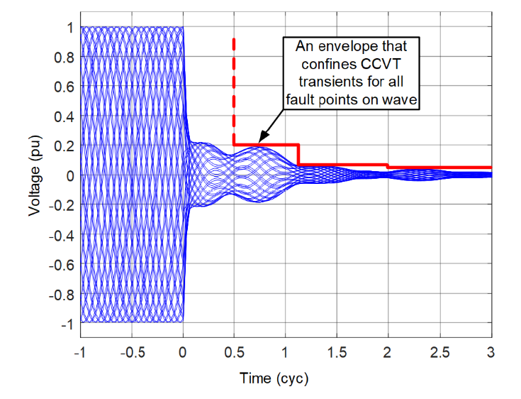
Figure 5 - Transient envelope for all possible CCVT transients for a given CCVT make and model
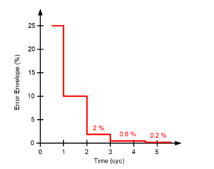
Figure 6 - Sample CCVT transient envelope (Class 3PT2 per IEC 61869-5 [9])
It is critically important to remember that the percentage error in the CCVT transient envelope (such as in Figure 6) relates to the pre-fault peak voltage and not to the fault ratio voltage. For example, the 10 percent error in Figure 6 is 10 percent of the nominal peak voltage. This value can be several times higher than the relay voltage during a fault in high SIR applications. As discussed in Subsection 3.2, this is a fixed error and not a ratio error. Therefore, the 10 percent transient error cannot be accommodated by pulling back the Zone 1 reach by 10 percent of the line impedance.
CCVTs have a long lifespan. It is unlikely that your in-service CCVTs comply with the transient accuracy classes of the IEC 61869-5 or IEEE C57.13.9 standards or that you have a record of the transient envelope for those CCVTs. Refer to the two standards [9] [10] and request the transient envelope information from the CCVT manufacturer. The CCVT manufacturer can provide you with the envelope or with just the sample test results – the secondary voltage plot for a fault at the voltage zero-crossing and for a fault at the voltage peak. In the latter case, you can use the maximum of the two transients to obtain the worst-case transient and draw a transient envelope as illustrated in Figure 7. The approach in Figure 7 is justified because the CCVT transients fall between the two extreme transient cases (for the zero-crossing and peak points on wave).
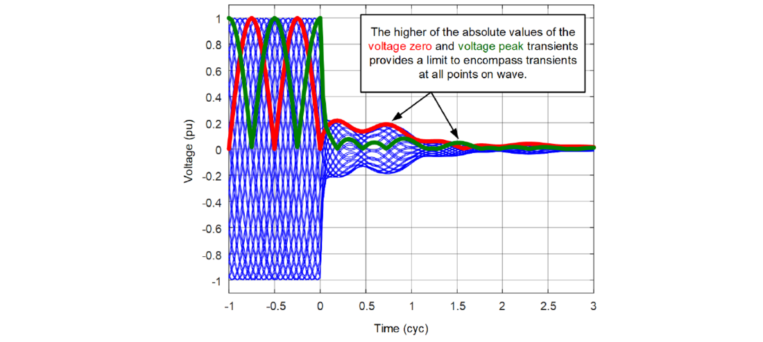
Figure 7 - Obtaining the CCVT transient envelope based on the absolute value of the secondary voltage plots for the fault at voltage zero (red) and voltage peak (green)
We are now ready to use the CCVT transient envelope to advance our Zone 1 security criterion (8). Because the envelope is an upper limit for transients that occur at any fault point on wave, we can substitute ECCVT with EENVELOPE. However, the envelope signal corresponds to the bolted fault at the CCVT location (the fault causes a change in voltage from 1 pu to 0 pu). We are concerned with faults at the remote bus. The change in voltage for a remote bus fault is:
(9)
The CCVT transient is caused by the change in the energy stored in the CCVT stack capacitors and inductors, primarily the tuning reactor. Therefore, the CCVT transient is proportional to the change in primary voltage that the fault causes. The CCVT envelope corresponds to a specific transient that occurs for the greatest possible change from 1 pu to 0 pu under any point on wave. Therefore, we write:
(10)
We can substitute the transient error in (8) with the transient envelope as in (10) and obtain:
(11)
Condition (11) uses a single point in time (T0) on the transient envelope. This is possible because the transient envelope, by definition, decreases with time (unlike an individual transient at a particular point on wave that may temporarily increase with the passing of time). Condition (11) brings an expected relationship between the operating time and security. Because the transient envelope decreases with the passing of time, adding a time delay (TD) or using a slower Zone 1 element (TOP) improves security: the greater T0, the smaller the EENVELOPE value.
3.4. Accounting for Relay Filtering
Condition (11) can be used directly to evaluate Zone 1 security. It would, however, yield overly conservative results. Zone 1 elements apply filtering to their voltage signals. Filtering reduces the CCVT transients that propagate into the Zone 1 element logic. We introduce an attenuation factor (A) for the CCVT transient to recognize that the relay filtering reduces the CCVT transients A-fold:
(12)
We have obtained a conservative estimate for the value of A by performing transient simulations. We expect our estimate of A to be a universal value because of the following explanation.
CCVTs are designed and tuned based on well-established rules. For example, the series reactor is tuned to zero out the phase shift between the primary and secondary voltages at the system nominal frequency. As such, the inductor value is not an independent parameter but is tied to the total CCVT stack capacitance and the system nominal frequency. Furthermore, certain other parameters of a CCVT can be neglected (winding resistances, for example). As a result, the transient response of a CCVT is controlled by a small number of parameters and is relatively universal [4] [11].
We simulated several CCVT designs by using an electromagnetic transient program to obtain a range of CCVT transient waveforms by varying the point on wave for a bolted fault. The true secondary voltage for a bolted fault is zero; and therefore, the measured secondary voltage is equal to the CCVT transient. We processed these transients with a range of filters (full-cycle Fourier and cosine) and estimated the ratio between the highest magnitude of the filtered CCVT transient and the maximum CCVT transient value in the window of the filter.
First, we scanned through all point-on-wave values to obtain the maximum CCVT transient for any given point in time. This maximum transient is related to the CCVT transient envelope in IEC 61869-5 and Draft IEEE PC57.13.9. Next, we calculated the filtered magnitude, took its maximum value for all points on wave, and related it to the envelope of the maximum CCVT transient in the window.
Figure 8 illustrates this process for one CCVT by plotting a range of CCVT transients (blue solid lines), the maximum absolute value within the 1-cycle data window (dashed blue line), and the range of voltage magnitude values after filtering with a full-cycle filter (red solid lines). At any point in time, the attenuation is the ratio of the maximum absolute transient value (dashed blue line) to the upper limit of the magnitude plots (red solid lines). The attenuation tells us how much the filtering reduced the CCVT transient. For example, if the maximum absolute transient is 0.2 pu and the upper limit of the magnitude is 0.05 pu, the attenuation is 4-fold (A = 4).
We selected the minimum value of the attenuation for a time larger than 1.5 cycles. This time threshold is justified by our experience that if a Zone 1 element misoperates in high SIR applications with CCVTs, it does so after 1.5 cycles.
We repeated this activity for a range of CCVTs and for a range of filters and obtained the worst-case (lowest) attenuation:
A = 2.5
A = 2.5 means that the CCVT transient envelope is reduced more than 2-fold – to 40 percent or less of its original value – when it passes through a practical relay filter.
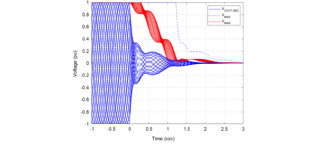
Figure 8 - Illustration of finding the attenuation value
Having the attenuation estimated (A = 2.5), we write our final Zone 1 security criterion as follows:
(13)
Condition (13) has a very simple form. The left-hand side in the inequality is the margin between the remote bus and the Zone 1 reach in per unit of the line impedance. The Zone 1 application is secure if that margin is greater than the right-hand side value in the inequality. The right-hand side is a product of the SIR, the CCVT envelope at the time of Zone 1 operation including the optional time delay, and the 0.4 factor associated with the relay filters. Condition (13) is easier to satisfy when:
- The Zone 1 reach is short.
- The SIR is low.
- The CCVT has a small transient envelope.
- The relay has a long operating time.
- The optional time delay is long.
The above is exactly what we intuitively expect in this application. We can use the variables in (13) to compensate for the impact of SIR in applications with high SIR values.
4. Step-By-Step Procedure for Assessing Transient Zone 1 Security and Examples
4.1. Step-by-Step Procedure for Verifying Zone 1 Security in High SIR Applications With CCVTs
Verify (13) separately for the Zone 1 phase and ground elements. If the security condition is satisfied, you can be confident that the Zone 1 application is secure. If the security condition fails, the Zone 1 application may still be secure, but you may need to contact the relay manufacturer or perform more studies or testing. Follow these steps to verify the security of the Zone 1 application.
- By using a short-circuit program and considering all credible contingencies, obtain the highest SIR value for your application.
- By using the Zone 1 operating time curves published by the relay manufacturer, obtain the operating time (TOP) for the SIR value from Step 1 and the farthest fault location for which the operating time is published.
- Decide on the per-unit Zone 1 reach (m1) and intentional time delay (TD). Start with the m1 value according to your standard practice, such as 0.75 or 0.80 pu, and TD = 0.
- Obtain the CCVT transient envelope from the CCVT documentation or manufacturer according to the IEC or IEEE standards. Obtain the per-unit envelope value for T0 = max(0.5 cycle, TOP – 1 cycle) + TD.
- Verify the security criterion:
- If the security condition is satisfied, you can be confident that the Zone 1 application is secure and you do not need to perform other studies.
- If the security condition is not satisfied, consider the following options:
- Consult the relay documentation to study the Zone 1 CCVT security claims; contact the relay manufacturer if necessary. Use the past field experience and any transient simulation studies for the same CCVT and relay makes and models.
- Use the security condition to determine if reducing the Zone 1 reach setting (m1), and by how much, would satisfy the security condition.
- Use the security condition to determine if adding an intentional time delay to Zone 1 (TD), and how much, would satisfy the security condition.
- You may also consider a combination of a shorter reach and a time delay. Typically, in high SIR applications, adding a time delay is more effective than reducing the reach.
- You may also consider using the security condition to obtain the required CCVT envelope and to help specify the CCVT for greenfield applications given the SIR value and the preferred relay.
4.2. Graphical Representation of the CCVT Security Criterion
Because the CCVT envelope is a graph, we can rearrange (13) to allow a graphical representation as follows:
(14)
We can use (14) graphically by plotting two lines on the CCVT transient envelope chart (Figure 9):
a horizontal line at:
and a vertical line at:
If the two lines cross above the CCVT envelope, then the application is secure. If the application is not confirmed to be secure, move the horizontal line up by reducing the Zone 1 reach, m1, and/or move the vertical line to the right by adding a time delay, TD.
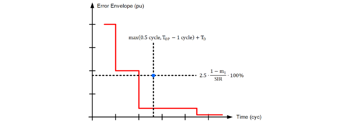
Figure 9 - Graphical illustration of the CCVT transient security condition
4.3. Transient Security Example 1
Assume a CCVT with the transient envelope shown in Figure 6 (Class 3PT2 per IEC 61869-5). Figure 10 shows the Zone 1 operating time curves of the applied relay. The preferred Zone 1 reach setting is 80 percent of the line impedance. Assume that by using the short-circuit program, you obtained the worst-case voltage of 0.065 pu at the relay location for a bolted remote bus fault. Calculate the SIR and obtain 1/0.065 – 1 = 14.4.
Is this Zone 1 application secure, and if not, what can be done to ensure security of the application?
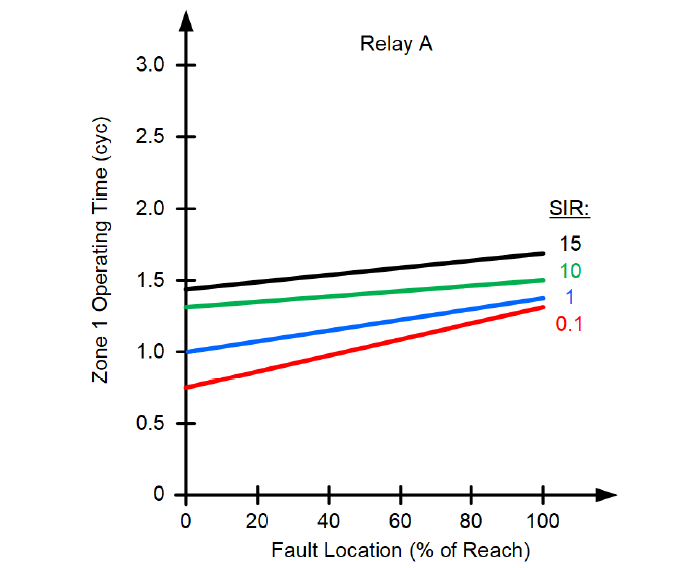
Figure 10 - Zone 1 operating time curves (Relay A)
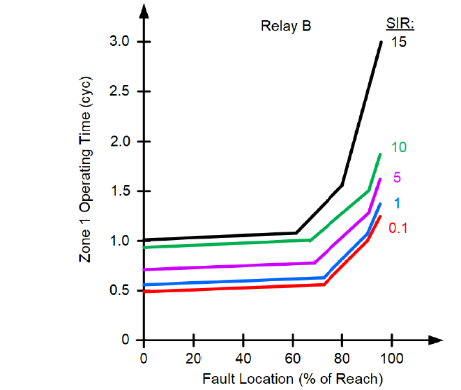
Figure 11 - Zone 1 operating time curves (Relay B)
We use the SIR value of 14.4 to determine the Zone 1 operating time for the farthest fault location in Figure 10 and obtain TOP = 1.5 cycles. We assume no intentional time delay (TD = 0) and the per-unit reach setting of m1 = 0.80. We obtain the CCVT envelope value for t = max(0.5 cycle, 1.5 cycles – 1 cycle) + 0 cycles = 0.5 cycle. From Figure 6, we see that the CCVT transient at 0.5 cycle is below 25 percent. We use the Zone 1 security criterion and calculate:
The above condition computes to:
0.2 > ? 1.44
The security criterion fails, and we cannot guarantee the phase Zone 1 security in this application without performing more studies or enabling CCVT security logic if it is available in this relay. If we decide to use an intentional time delay, we will need to delay the operation until the CCVT envelope falls below:
From Figure 6, we see that the CCVT transient error envelope falls below 3.47 percent (to 2 percent) at 2 cycles; therefore, we calculate TD from this equation, 1.5 cycles – 1 cycle + TD = 2 cycles, and obtain TD = 1.5 cycles. With a 1.5-cycle intentional time delay, we can guarantee security of this Zone 1 application without testing or obtaining any more details from the relay manufacturer.
If we decide to shorten the reach instead, we will calculate the reach as:
which computes to:
m1 < -0.44 pu
The maximum reach being negative means that Zone 1 security cannot be ensured by reducing the reach.
4.4. Transient Security Example 2
Assume the same CCVT as in Example 1 but consider that a different relay is used (Figure 11).
We use the SIR value of 14.4 to determine the Zone 1 operating time for the farthest fault location in Figure 11 and obtain TOP = 3 cycles. We assume no intentional time delay (TD = 0) and the per-unit reach setting of m1 = 0.80. We obtain the CCVT envelope value for t = max(0.5 cycle, 3 cycles – 1 cycle) + 0 cycles = 2 cycles. From Figure 6, we see that the CCVT transient at 2 cycles is below 2 percent. We use the Zone 1 security criterion and calculate:
The above condition computes to:
0.2 >? 0.115
The security criterion is satisfied, and we can guarantee the phase Zone 1 security in this application without performing further studies.
We can use the graphical method to illustrate the above two examples. Figure 12 shows the CCVT envelope and the points representing Relays A and B with the reach set to 80 percent of the line impedance.
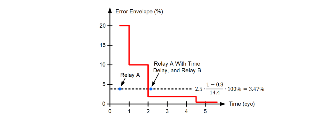
Figure 12 - Graphical illustration of CCVT Examples 1 and 2
5. A New Format for Specifying Zone 1 Transient Overreach
The CCVT classes create an opportunity for the relay manufacturers to provide a more comprehensive Zone 1 application recommendation for the CCVT classes specified in IEC 61869-5 and Draft IEEE PC57.13.9. A CCVT class constrains the CCVT transient error and allows the relay manufacturer to specify the Zone 1 transient overreach with that CCVT as a function of the Zone 1 reach, CCVT security setting (enabled/disabled), SIR, and intentional time delay.
We suggest using the format shown in Figure 13. We label this specification as “Zone 1 security chart.” A separate chart may be provided for each CCVT class. The two CCVT standards specify a total of five CCVT classes. The chart may be different for the Zone 1 phase and ground elements. The chart will be different based on any CCVT security logic being disabled or enabled if the relay includes a setting to control the additional security logic. The Zone 1 security chart would reflect all proprietary CCVT security logic in the relay and therefore would be more accurate than the generic Zone 1 security criterion that we presented in Section 3. Such a chart may be considered for inclusion in future revisions of IEC 60255-121 [12] or IEEE C37.113 [5].
The users may also adopt and develop Zone 1 security charts as in Figure 13 as a part of their line protection standards. These user charts can be based on information from the relay manufacturers, transient testing results, and field experience.
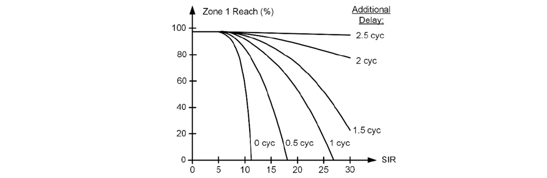
Figure 13 - Proposed Zone 1 security chart (specific to a given CCVT class and relay make and model)
6. Conclusions
In this part, we have presented an engineering method for quantifying the Zone 1 security in high SIR applications, including the CCVT transients. Part 2 [1] discusses VT and relay measuring errors, GPR, and mutual coupling. We have shown how to use the error estimates to verify the Zone 1 security and how to change the application parameters to ensure security.
We have introduced a novel method to assess the impact of CCVT transient errors on the Zone 1 security. Our method brings together all the key factors that impact transient Zone 1 security: the SIR, the CCVT transient response, and Zone 1 inherent operating time, reach, and additional time delay, if applied. You can use the Zone 1 security criterion to both evaluate the Zone 1 security and calculate the reach setting and additional time delay to ensure security. You can also calculate the SIR limits for a secure Zone 1 application with desired settings given the relay and CCVT makes and models. You can also use the security criterion to specify the CCVT transient response that would ensure a secure Zone 1 application for a particular SIR, relay make and model, and Zone 1 settings.
If we expect to set the Zone 1 reach to 80 percent of the line impedance but want to avoid finding any CCVT and relay data and instead assume the worst-case CCVT transients, we can apply the Zone 1 element if the SIR is below 0.63, assuming the steady-state errors require a margin that is less than 10 percent.
If we expect to set the Zone 1 reach to 80 percent of the line impedance and assume the total steadystate voltage error is below 2.5 percent of nominal (VT and relay errors, no GPR or mutual coupling to a line that carries significant current), we can apply the Zone 1 element when the SIR is less than 3, assuming the transient errors require a margin that is less than 10 percent.
We can state that it is very unlikely that in systems with SIR values below about 0.63, a typically set Zone 1 element (an 80 percent reach setting) would overreach because of the CCVT transients, regardless of the CCVT and relay makes and models.
References
- B. Kasztenny and R. Chowdhury, “Security Criterion for Distance Zone 1 Applications in High SIR Systems With CCVTs – Part 2: Steady-State Errors,” proceedings of the 2024 CIGRE Canada Conference & Exhibition, Winnipeg, MB, Canada, 2024.
- B. Kasztenny, “Settings Considerations for Distance Elements in Line Protection Applications,” proceedings of the 74th Annual Conference for Protective Relay Engineers, College Station, TX, USA, 2021.
- B. Kasztenny and R. Chowdhury, “Security Criterion for Distance Zone 1 Applications in High SIR Systems With CCVTs,” proceedings of the 76th Annual Georgia Tech Protective Relaying Conference, Atlanta, GA, USA, 2023.
- B. Kasztenny, D. Sharples, V. Asaro, and M. Pozzuoli, “Distance Relays and Capacitive Voltage Transformers – Balancing Speed and Transient Overreach,” proceedings of the 54th Annual Georgia Tech Protective Relaying Conference, Atlanta, GA, USA, 2000.
- IEEE Std C37.113-2015, IEEE Guide for Protective Relay Applications to Transmission Lines.
- H. J. Altuve Ferrer and E. O. Schweitzer, III (eds.), Modern Solutions for Protection, Control, and Monitoring of Electric Power Systems, Schweitzer Engineering Laboratories, Inc., Pullman, WA, USA, 2010.
- P. G. Mysore and J. U. Berzins, “Impact of Voltage Transients and System Impedance Ratio on Zone 1 Distance Relay Reach,” proceedings of the 56th Annual Minnesota Power Systems Conference, Saint Paul, MN, USA, 2020.
- M. Thompson, D. Heidfeld, and D. Oakes, “Transmission Line Setting Calculations – Beyond the Cookbook Part II,” proceedings of the 48th Annual Western Protective Relay Conference, Spokane, WA, USA, 2021.
- IEC 61869-5:2011, Instrument Transformers – Part 5: Additional Requirements for Capacitor Voltage Transformers.
- IEEE Std PC57.13.9, IEEE Draft Standard for Power-Line Carrier Coupling Capacitors and Coupling Capacitor Voltage Transformers.
- B. Kasztenny, W. J. Premerlani, and I. Raducanu, “Self-adjusting voltage filtering technique compensating for dynamic errors of capacitive voltage transformers,” U.S. Patent 7,567,881, July 2009.
- IEC 60255-121:2014, Measuring Relays and Protection Equipment – Part 121: Functional Requirements for Distance Protection
Biographies
Dr. Bogdan Kasztenny has 35 years of experience in power system protection and control. Bogdan has designed, applied, and supported protection, control, and fault-locating products with their global installations numbering in the thousands. Bogdan is an IEEE Fellow, an IET Fellow, a Senior Fulbright Fellow, and a Distinguished CIGRE Member. He has authored over 250 technical papers and holds over 60 U.S. patents.
Ritwik Chowdhury (M.Sc.) is a principal engineer at Schweitzer Engineering Laboratories, Inc. Ritwik holds over 15 patents and has coauthored over 30 technical papers. He is the chair of the Protection and Control Practices Subcommittee (I-SC) of the IEEE Power System Relaying and Control (PSRC) Committee and the recipient of the 2021 PSRC Outstanding Young Engineer Award. Ritwik is a senior member of IEEE, a member of CIGRE, and a registered professional engineer in the province of Ontario.