Engineering the Future: Optimizing Power Transformer Performance in Renewable-Powered Grids
Author
Dan MARTIN - Essential Energy, NSW, Australia

Summary
There is a substantial energy transition underway in Australia as many solar farms and battery energy storage systems (BESS) connect to the MV distribution grid. The utilities have therefore been investigating the impacts of these systems on zone substation infrastructure, which was mostly designed before the need to handle large reverse flows of power. The challenge becomes one of optimisation of capacity and understanding options to improve network utilisation, especially as the community is also changing the utilisation by installing rooftop PV and household batteries. Asset management of large plant such as power transformers and zone substations becomes key because of the substantial investment required, and the desire to avoid stranded assets resulting from unexpected changes. The uncertainty in the changing energy environment makes forming a strategy to manage the lifecycle of transformers difficult, although in general the longer they are kept in service the more information about changing energy systems becomes available.
In this article a discussion is given of how the legacy power transformer fleet is being managed and evaluated for use with the new energy future. It is split into the following sections. Firstly, the expected changes in grid usage and transformer stresses. Secondly, the establishment of a framework to establish and manage transformers. Lastly, the key stresses unknown to occur and how they impact transformers. This is considered a journey wherever higher levels of distributed energy resources will be connected. In these scenarios the market develops new solutions, and there will be different options available to the utility to manage. CIGRE reliability surveys have consistently pointed to power transformers lasting many decades, and for our network there are many specification, design and construction vintages from nearly sixty manufacturers. Thus, there is no one-size-fits-all approach.
When determining whether a new solar farm or BESS can connect to a transformer, its existing load profile is checked ensuring extra capacity is available. Ideally, substation assets will not need to be replaced in the near term by larger units, which increases costs. However, there are fast-paced changes underway in what the community connects to the grid, which are the increasing quantities of rooftop PV, residential battery storage and electric vehicles. Consequently, a complex fast evolving system is developing at the distribution level which needs to be considered when determining the available capacity of a transformer for a large solar farm. Historically, network capacity was designed to handle seasonal peak demand, allow for growth, and to maintain redundancy for when components are offline or have failed. Designs were often conservative because utilities had limited control over customer loads. Now, there are more options to consider which automatically manage peak usage, such as transformer runback schemes and dynamic operating envelopes.
Within the Australian market there are different requirements for generators under and over 5 MW (in chapters 5 and 5A of the National Electricity Rules [1]). Consequently, many enquiries are for blocks of 4.99 MW, in comparison with many rural power transformers with a rating between 5 and 10 MVA. There have been enquiries for more than one solar farm to be connected to some substations which can lead to possible transformer overloading if not managed correctly, especially during hot days or during unusual circumstances where there is unusually low local load.
Introduction
Essential Energy builds, operates and maintains one of Australia’s largest electricity distribution networks, providing a vital service to over 900,000 homes and businesses across regional, rural and remote communities. Our network footprint covers 95 per cent of New South Wales and parts of southern Queensland, traversing 737,000 square kilometres of diverse landscape from the desert to the coast, across alpine to sub-tropical.
Nearly 800 power transformers are operated across the footprint and using innovation and technology, we are actively supporting the energy transition. A programme is underway to review transformer management strategies to handle the forthcoming inclusion of solar farms in conjunction with the expected take-up of community technologies like solar, EVs and batteries. Around fifty zone substations at present experience reverse power flow from a solar farm or rooftop PV, which will increase into the future. As of writing many BESS installations are also planned to connect.
The intended benefit of this work is to manage infrastructure efficiently by transparently determining the long-term impacts of solar farms on utility assets, so effective lifecycle decisions can be made. Developers are keen to invest in renewable generation. The state and federal governments are looking to decarbonise, while retaining a sustainable network. The community desires affordable, safe and reliable energy while being able to connect new technologies to the network. Careful asset management of power transformers is required to ensure that lifecycle costs do not unnecessarily escalate. Such as understanding the value statement of keeping old plant in service until end of life and accepting constraints, versus retirement and a new unit fully specified for use with distributed energy resources (DER).
The project stages have been:
- Understand impacts of solar farms and BESS on existing utility transformers, so these impacts can be managed. As transformers have been sourced from nearly sixty manufacturers, over many decades, some have idiosyncrasies because they were specified before DER became mainstream. Internal case studies have been performed and meetings with other utilities and manufacturers (e.g. through CIGRE networks).
- Create a framework to sort transformers into three lists: transformer is fully compliant with proposed reverse power flow; transformer has constraints limiting use; or transformer is not compliant with proposal. Some transformers have been derated, for instance used as a backup to a site where usage is limited to one month a year. Thus, reverse power flow per se is not the constraint but the expected new load profile with the solar farm or BESS.
- Define the targeted monitoring, either to operate transformers close to their technical limits or where experience is limited and a risk is considered to exist. Normal practice is to only fit temperature indicators with remote monitoring to transformers which will operate at high load (>80 %). Many sites are in rural or remote areas where the load is small, and so there is little value perceived in remote temperature monitoring. For high use sites, when remote temperature monitoring is installed the residual life of the transformer insulation can be calculated and then used to drive augmentation decisions [2].
- Investigate automation options where curtailing solar or BESS is the preferred option over limiting the rating or augmenting the network. The downside to only monitoring is that the utility traditionally has had limited control over loads during very hot days, e.g. over 45 °C, and so keeps capacity spare. A better solution could be automation of solar and BESS to ramp up or down and reduce the transformer’s load for a few days a year, unlocking the spare capacity on the cooler days. The spare capacity of a transformer will also be influenced by increases in rooftop PV export.
- Consider how to implement findings in the existing asset management system [3]. Asset maintenance plans are reviewed normally every three years. Any potential impacts on resource availability and capability are carefully considered with field teams. Changes are effectively communicated throughout the team.
Changes in grid usage and stresses on power transformers
In line with industry and CIGRE-member experience, the life of a power transformer is typically at least fifty years, and so many different technologies, designs and manufacturing techniques have been used. The utility is an amalgamation of three previous organisations, and so there were different engineering philosophies. This leads to the challenge of having to evaluate a wide range of assets where there is sometimes no manufacturer remaining to advise.
Figure 1 shows the key impacts which have been identified. As well as considering the impact on the transformer itself, there is also the behaviour of the wider network which is influenced by the properties of the transformer such as voltages.
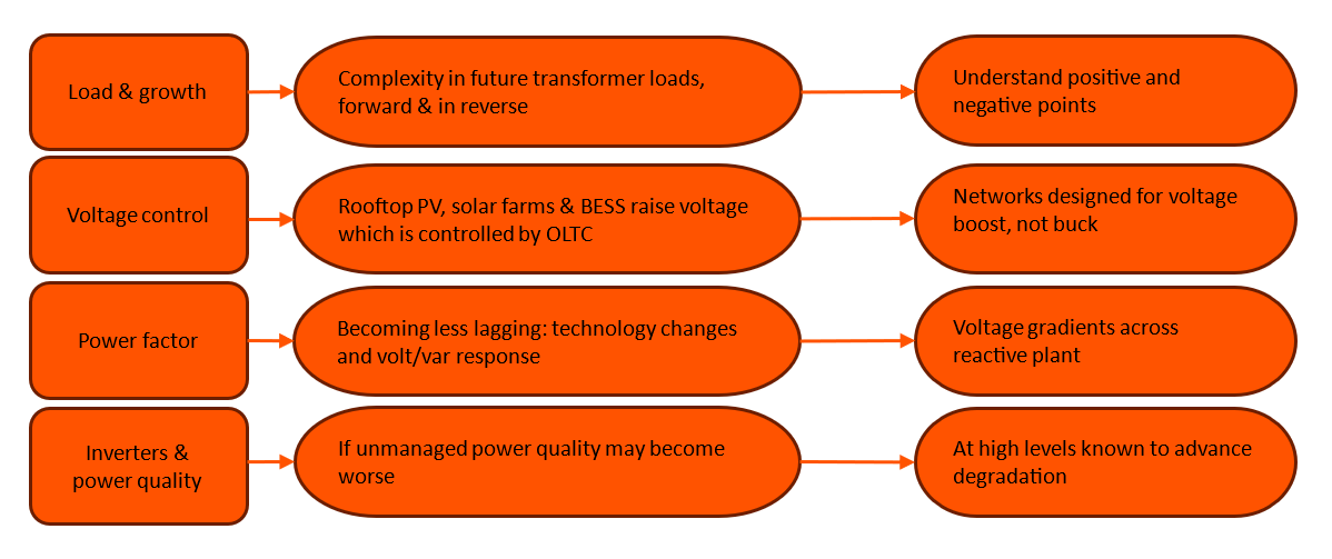
Figure 1 - Key impacts
Load & growth
Local solar generation has the initial benefit that it offsets the upstream substation load, which in Australia is normally highest around midday because of hot days and air conditioning. With this offset, transformers will operate cooler during the hottest part of the day, extending insulation life which is temperature dependent [4]. However, as the uptake of rooftop solar along with solar farms continues, a transformer will eventually be loaded into reverse and again operate at high temperatures during the hot day. If the local load is not present one day, for instance a public holiday, then the transformer will be loaded even higher in reverse. Across Australia rooftop solar is predicted to continue growing over the coming years, with utilities considering the export limits and whether there can be an increase in this. Therefore, a challenge when connecting a solar farm is deciding whether to reserve transformer capacity for this future growth.
During planning the historic load profile of a substation is used to ascertain spare capacity. However, this assumes that the load diversity will remain similar over time. Another option is to consider the worse-case loading, for instance the solar farms are at full export but there is minimal local load. However, as such a situation might be unlikely, this approach reduces the substation utilisation. A balanced approach is required to ensure that customer supply is maintained even during unusual or contingency events.
BESS and residential batteries are entering the market as costs fall, changing the load profile of the zone substation. For the large-scale BESS there is a market benefit to sell the energy into the grid in the evening, with the batteries charging during the day when electricity is cheap. However, without control a solar farm and BESS could act independently if there is no local generation one day and the BESS is charging through the transformer. The BESS could also discharge during the day along with the solar export if the market price for electricity is an incentive. Remedial Action Schemes (RAS) [5] are being proposed by the regulator to prevent assets being overloaded. Once the transformer reaches a load or temperature limit, a signal is returned to the generator or BESS to reduce utilisation. Transformers in NSW are expected to operate in high ambient temperatures, such as above 45 °C in some areas, while still supplying peak air conditioning loads. This also means that there is often spare capacity during cooler days. Without a RAS a utility may be conservative in determining the available capacity for a solar farm to prevent the transformer overheating on such days if there is no control over the generator or load.
Voltage control
It is well known that reverse power flow elevates the line voltage, and thus management is required to minimise this impact. Rural networks were designed to supply inductive loads like fans, agricultural pumps and motors far from the substation. Substation voltage control was often specified to boost the voltage for high loads, and in some cases the voltage was elevated at the substation to compensate for the expected line voltage drop.
Most power transformers on the Essential Energy network have on-load tap changer (OLTC) control. With reverse power flow some of these have been seen to move to their last position. In many cases the OLTCs were specified with more positions to boost the voltage than buck, for instance +16% to -6%, and so the last bucking position is soon reached. There is a programme underway to reduce the customer voltage from 240 V to 230 V, which might not be possible to achieve with solely the OLTC.
Another problem with some old OLTC designs is that the internal arrangement of transition resistors significantly limits reverse power flow [6]. Solutions have been made available to change these resistors and permit more reverse flow. The utility is currently trialling these options with considerations to maintenance overheads.
Power factor
As consumer loads have become inverter-based the power factor has been seen to become unity or leading (e.g. [7]). For example, pumps and motors are supplied by inverters. Manufacturers may use capacitors in power quality filtering to comply with standards. The challenge of a capacitive load is that this creates a voltage rise across the transformer, instead of a voltage drop, moving the OLTC closer to the end of its range. Transformers have a lot of reactance because of the core steel and magnetic fields. In normal circumstances the downstream load is usually slightly inductive, and so there is a voltage drop across the transformer. When there is a flow of reactive power upstream then there will be a voltage rise instead. An example is shown in Figure 2 where the power transformer tap changer was reaching its limit, and when the power factor was rebalanced away from being capacitive the tap changer returned to mid-position. A utility may have installed capacitor banks in a substation for power factor balancing which may not be required any more. In NSW many of these capacitor banks are manually switched, and so control is not automatic.
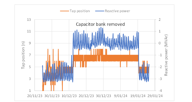
Figure 2 - An example when a tap changer was found reaching its last position and the cause was the reverse flow of reactive power from a downstream capacitor bank. Once this capacitor bank was removed there was less reactive power generated and the tap position moved to a central position.
Inverters and power quality
Excessive harmonic loads are known to increase transformer operating temperatures [8]. Normally, these loads are controlled through the agreement with the inverter operator. A recommendation given in IEC 60076-1 is that transformers are designed to operate when the total harmonic distortion of the supply voltage is less than 5%, and the load current harmonics content is also less than 5% of its rated value [9]. Periodic checks are performed by the utility to ensure that these criteria are met.
While oil and winding temperature (OTI and WTI) gauges are used with a transformer, the WTI is only calibrated during a heat run test to the hotspot temperature. Thus, it is unlikely to show a temperature rise being caused by harmonics and thus power quality measurements are required.
An uncertainty is how the power quality will change when more than one solar farm is connected to a substation, and if there are undesirable interactions between them. We are planning to study these situations and if necessary update policies.
While heating from harmonic loads is well documented, the potential impact from voltage pulses is less known. A CIGRE brochure about insulation degradation under fast, repetitive voltage pulses [10] noted that the inception voltage of partial discharge falls. However, the susceptibility of old designs and their internal insulation clearances to this degradation mode is still uncertain. Our initial experience has not found changes in test measurements indicative of the onset of partial discharge, such as changes in dissolved gas concentrations, and none of the other local utilities have advised us that this has occurred in their plant. This possibility of this failure mode is noted and will be investigated further if changes are observed.
Establishing framework
The intended benefit of the framework is to ensure that risks and costs are identified, assisting with planning and upfront cost recovery. The general strategy, Figure 3, is to firstly determine if the design of a transformer is suitable for connection to a solar farm by identifying constraints. The second step is to establish the actual rating, which may be different from the nameplate. This rating takes into account condition and any constraints around the substation. If an asset is unsuitable, it may be possible to make it available by refurbishing or modifying technology. The transformer fleet is sorted into the following three lists based on technical compatibility with the proposed solar farm.
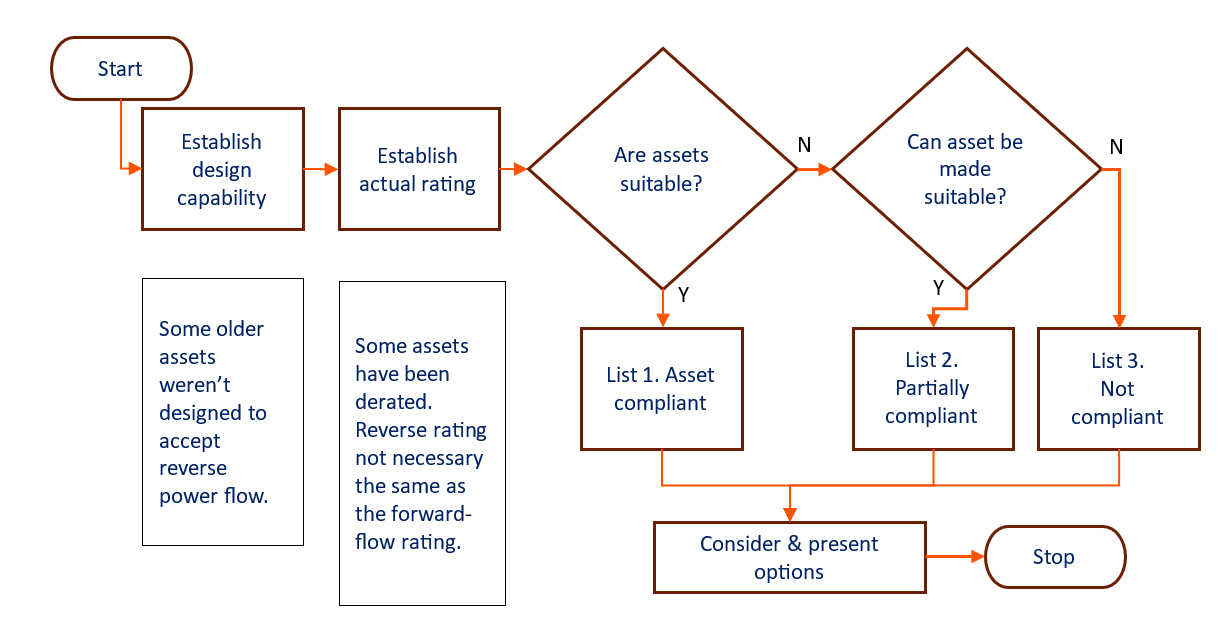
Figure 3 - Framework for grading suitability of assets
List 1: Asset design and condition fully capable of use with the proposed solar farm. The configurations of transformers and components are tracked in an asset management database, which have been reviewed for functionality with reverse power flow. Any discrepancies are highlighted and reviewed.
Further online monitoring may be required to operate assets closer to technical limits, like oil and winding temperatures, dissolved gas analysis, power quality and alarms, connected to the SCADA system.
List 2: Assets which in their present state are partially suitable for the proposed solar farm, although work is required to make them fully compliant. Some examples are as follows:
- A conditional analysis indicates that an asset must be maintained or refurbished to return to list 1, before use at high load. The guidance to set up asset health indices given in WG A2.49 is used [11]. This refurbishment can either be minor and onsite, or a recommendation to return to factory taking into consideration logistics, costs and benefits.
- If the OLTC is near the end of its range then there may start to be voltage rise problems with the solar farm. A further analysis should be performed to understand how much solar can be hosted by the downstream network before the OLTC reaches its end and the voltage begins to elevate. Some OLTCs are asymmetrical, having many boosting positions and only a few bucking ones.
- Some old OLTC designs have reverse power flow limits in the switching mechanism.
- Some OLTC designs cannot be run at rated power on all tap positions.
- In some areas the high ambient temperatures provide a constraint, which can sometimes be overcome by installing cooling fans, control and alarms monitored using SCADA.
- Seals and gaskets may need to be replaced because oil leaks may be worsened from the oil operating at a higher temperature, due to reduced viscosity.
List 3: Assets which are unsuitable for use with the solar farm, and replacement could be the preferred option. A runback scheme may also be suitable, however it depends on the magnitude of the constraint. Examples are:
- The solid insulation is clearly nearing its end of life and raising the load will substantially and unacceptably reduce the remaining life.
- The transformer has little life remaining, and so refurbishment is not seen as economical or practical compared to the cost of a new asset.
- Transformer has been derated due to its condition.
- OLTC design cannot support the required reverse power flow, either insufficient buck positions or an old type of tap changer which has constraints.
- A deenergised tap changer is used, which is unable to automatically control the downstream voltage. An external regulator may be an option.
- Inability to maintain N-1 reliability in the zone substation without an automated method to control solar and BESS.
- Any idiosyncrasies identified in the zone substation which cannot be readily changed.
Also noted is that economics also impacts investment decisions. A proponent could look to connect to a different part of the network.
Aspects relating to condition and actual rating of a power transformer
Most power transformers on our network were designed before the need to connect solar farms. Thus, a comprehensive model, Figure 4, has been developed to ascertain appropriateness. Where possible CIGRE brochures and IEC standards are used.
As has been described previously the OLTC might not be suitable for the reverse power flow, for instance either at the end of its run and cannot buck the voltage further, or with internal limitations. This could influence the reverse power flow rating.
The utility normally expects around sixty years of operating life from a transformer. An estimation is applied to determine the residual life of solid insulation with a solar farm and BESS attached, and check that this is not shorter than our expectation for life [2].
As engineering standards have been continuously updated some old plant might not be capable of operating over the rated load, for instance the bushings, tap changer, protection or cables being the constraint. Upgrading the cooling using fans can be an option for certain designs, along with the monitoring of this system.
The condition of an asset is investigated using the methods shown in the A2.49 brochure [11], in particular, metrics are used to identify which test measurements are showing abnormal operation for further review. Some old assets have shown signs of degradation and have been derated so they can remain in service. Asset health indices have the benefit of highlighting problems in large asset populations, which are then reviewed by an expert and a decision made.
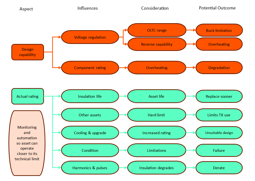
Figure 4 - Power transformer analysis framework.
Next steps
It is understandable that some areas will continue to see ever higher levels of renewable generation, and thus careful management of the utility asset base is required. These transformers and solar farms will be continually monitored and adjustments made to policies when required. The industry will learn from experience as more solar farms are connected. The configurations of transformers and components and suitability for reverse power flow will be updated from experience, using the asset management database.
In terms of condition monitoring, transformers connected to solar farms will be treated as a subpopulation and any trends tracked and monitored. For example, the lowering of the partial discharge inception voltage has been observed in laboratory testing. If this is detected during testing then further investigation will be performed. Current maintenance practices require a DGA measurement annually, unless otherwise specified.
Historically, a distribution utility has had little control over downstream loads or generation. Thus, planning decisions around the loading of transformers were conservative to prevent overheating, trips and outages. Transformer runback schemes connected to generators and large loads can be an accepted option. However, the utility still needs to manage settings and congestion on high-use days, especially when multiple solar farms and BESS systems are connected.
The potential interaction between solar farms and community rooftop solar will be monitored. As a transformer runback scheme is connected to the solar farm, priority is given to community rooftop solar. However, if solar farms raise the voltage substantially then the volt-watt control of small inverters used by the community will ramp down export, in accordance with AS/NZS 4777.2 [12]. This may require changes in the coordination and usage of the OLTC, before downstream network augmentation is considered.
The opinions expressed in this article by the author are not necessarily those of Essential Energy.
References
- Australian Energy Market Commission, National Electricity Rules, accessed 26/2/25, online
- D. Martin, F. Zare, G. Caldwell and L. McPherson, "Calculating the residual life of insulation in transformers connected to solar farms and operated at high load," IEEE Electrical Insulation Magazine, vol. 36, no. 6, pp. 10-20, Nov.-Dec. 2020, doi: 10.1109/MEI.2020.9222630. [online]
- Asset Management Distribution Annual Planning Report 2023, Essential Energy, Australia, 2023. [online]
- H. Pezeshki, P. J. Wolfs and G. Ledwich, "Impact of High PV Penetration on Distribution Transformer Insulation Life," in IEEE Transactions on Power Delivery, vol. 29, no. 3, pp. 1212-1220, June 2014, doi: 10.1109/TPWRD.2013.2287002. [online]
- Remedial Action Scheme Guidelines, Australian Energy Market Operator, Version 1.0, 2022. [online]
- V. Levi, M. Kay and I. Povey, "Reverse power flow capability of tap-changers," CIRED 2005 - 18th International Conference and Exhibition on Electricity Distribution, Turin, Italy, 2005, pp. 1-5, doi: 10.1049/cp:20051241.[online]
- D. Martin, F. Geth, K. Lucas and R. Watson, "Implications of managing distribution network assets with a very high level of solar generation: New Zealand experience," in CIGRE CIDER and Cairns International Symposium conference, 2023.
- IEEE Standard C57.110-2018, "Recommended Practice for Establishing Liquid Immersed and Dry-Type Power and Distribution Transformer Capability when Supplying Nonsinusoidal Load Currents," 2018 [online]
- IEC 60076-1, Power transformers – Part 1: General, 2011. [online]
- CIGRE WG D1.43, "Insulation degradation under fast, repetitive voltage pulses," brochure 703, 2017.
- CIGRE WG A2.49, "Condition assessment of power transformers," brochure 761, 2019.
- Australian/New Zealand standard 4777.2:2020, “Grid connection of energy systems via inverters Part 2: Inverter requirements”, 2020 [online]
Biography
Dan Martin is a chartered professional engineer with over twenty years of experience. He is a senior engineer at Essential Energy, which is a state-owned electricity infrastructure company in Australia. As part of the zone substations team his current responsibility is asset management of the 800 power transformers in the utility fleet, understanding directions in community and industry energy usage, and shaping the future.
He is a chartered member of Engineering New Zealand, a senior IEEE member and a registered professional engineer of Queensland. He has a Masters in Engineering Project Management from the University of Auckland, New Zealand, a PhD in electrical engineering from the University of Manchester, and a B. Eng. (Hons) in electrical and electronic engineering from University of Brighton, both from Great Britain.