Transitioning to differential protection for offshore wind collector cables using passive sensing
Authors
Steven BLAIR, Aneesh CHANDRAN - Synaptec
Bogdan KASZTENNY - SEL
Alexander TSYLIN - Ørsted

Summary
This paper starts with a review of requirements and best practices for protecting offshore wind farm collector networks. It then describes a system for current differential protection of the array cables that is based on passive sensing. The system avoids installing electronic devices at the wind turbine generator locations and instead uses classical current transformers interrogated remotely by using optical fiber and passive interface devices. The paper describes two versions of the differential protection scheme and compares it with the conventional overcurrent and distance protection as well as with the hypothetical brute-force bus differential or process bus-based protection. The key advantages of the proposed system are improving speed and sensitivity of protection, making the protection less dependent on fault current contributions, and allowing fast reconfiguration to minimize loss of generation.
Keywords
Differential protection, offshore wind, passive sensing1. Introduction
Offshore wind farms interconnect a set of wind turbine generators (WTGs) by daisy-chaining them on a string of subsea intra-array cables (IACs) which is connected to the main bus of the collector substation. Typically, several IACs are used per substation to connect many WTGs. The collector substation is grounded, typically via a grounding transformer. A grounding resistor can be used in the neutral of the grounding transformer to limit the ground fault current yet provide sufficient limitation of overvoltages while allowing ground overcurrent protection for the cables. The IACs are typically operated as radial feeders, but they may be looped to provide better network availability after cable failures that require a long time to repair. Disconnect switches are typically installed at each WTG to allow isolating the WTG and the cable downstream from the fault.
Because the fault current contribution from the grid for IAC faults is typically much higher than from the WTGs, overcurrent and distance protection is used to protect the IACs and to provide backup for some WTG faults [1], [2], [3]. Typically, a set of sensitive backup protection functions for IACs (including 46 and 59N) and the upstream transformer’s incomer should trip an uncleared fault before WTGs go offline. In some cases, the system relies on the WTGs tripping offline for uncleared faults based on the voltage outside of the WTGs’ fault ride through (FRT) envelope.
The overcurrent and distance protection schemes are economical. However, they face several limitations, including infeed from the WTGs located on the faulted cable, capacitive current from all healthy cables, and the resistive nature of the ground fault current if a fault limiting resistor is used [3]. As a result, the overcurrent and distance protection schemes may not be very dependable.
Additionally, the overcurrent and distance protection schemes are not fully selective and are not able to pinpoint the faulted IAC between two WTGs. Overcurrent and distance protection schemes are normally time delayed. As a result, fast reconfiguration cannot be performed (because the faulted IAC is not certain) resulting in an outage of the entire IAC and all its WTGs. Locating faults requires active (injection-based) methods and is both costly and time consuming.
Offshore wind operators can benefit from fast-acting and reliable protection for cable networks, including the export cables delivering power to the grid, and IACs between WTG locations. The main objectives are faster fault clearance and improved opportunities for post-fault reconfiguration, which reduces outage time and costs, including minimizing the loss of generation. In some regions, fast fault clearance for IACs might be required by the local grid codes, particularly for 132 kV systems. There is also the potential for de-rating of cables in some cases if faster fault clearance, compared to conventional overcurrent schemes, can be guaranteed.
Differential protection provides excellent fault discrimination and trip times. Differential protection requires a communications channel, and fiber optic links are already available between WTG locations and the collector substation. However, there is a lack of scalable options on the market based on conventional instrumentation which can be applied to the offshore wind collector networks (typically up to a dozen cable sections with a dozen tapped WTGs).
Traditional line current differential (87L) schemes do not fit this application well. These schemes are typically developed for two- or three-terminal applications (with some solutions available for up to six terminals) and cannot be readily scaled up to a network with a dozen taps and sections. Distributed multi-zone bus differential (87B) schemes can be used in theory, but they require electronic devices, control power, networking equipment, time synchronization, and maintenance access at each of the WTG locations along the string.
Passive sensing has been proven in transmission networks for protecting hybrid (a combination of cable and overhead line sections) and other complex circuits. It can be directly applied in offshore networks to monitor currents at WTG locations, including at the terminations of each IAC section. A passive sensor connects to the secondary of a conventional current transformer (CT), but no control power or other infrastructure is required at the CT locations. Only optical fiber, which is readily available in offshore systems, is required to connect the sensors. An interrogation system located within the collector substation can centrally access all measurements via the fiber. Such a distributed differential protection system is simpler to deploy compared with a process bus-based approach which would require providing control power, data communications, and time synchronization to merging units at the WTG locations.
This paper starts by reviewing protection and fault locating requirements and present best practices for offshore collection networks (Section 2). Next, it outlines two options for a new current differential protection scheme based on passive sensing (Section 3). Option A involves installing new CTs or using the existing CTs at the outfeed of each WTG. These CTs allow one large unit protection zone, covering the entire string of WTGs, similar to substation busbar protection but distributed over the string of WTGs. Option B requires installing CTs at each end of each of IAC sections (i.e. in both connections to the WTG tap) to create a unit protection zone per cable section. This approach scales to any number of cable sections on the string. It provides fast and granular fault clearance and fault locating, and optimal post-fault restoration. Optionally, CTs could be installed at the outfeed of each WTG, as for option A, to create additional zones around the busbar within each turbine platform. This adds granular protection for faults in the WTG busbar. Additionally, having access to the WTG current, the proposed system can provide overcurrent backup protection for the WTG that is more sensitive and better coordinated compared with distance backup applied at the substation and looking into the array and several WTGs.
2. Background
2.1. Protection and fault locating requirements for offshore wind networks
The protection requirements for offshore wind collector networks are shaped by several factors. These include the mandates of local grid codes and connection agreements, the configuration and technical parameters of the collector system, the design specifications of IACs, economic considerations such as power generation and transmission availability, and broader business case requirements. Additionally, the wind farm developer’s established protection best practices, the range of available technologies, and the off-the-shelf solutions offered by protection system manufacturers also play pivotal roles in shaping the overall protection philosophy.
Generally, the protection system for the IACs should be designed considering the following requirements:
- Main and backup protection functionality. The protection system should provide main and local backup protection for IACs as well as remote backup protection for WTGs.
- Selectivity. The protection system should coordinate with the WTG protection functions.
- Sensitivity. The protection system should be sensitive to all types of faults on the IACs and for certain fault types in the WTGs.
- Speed of operation. Fault clearance time provided by the protection system for all types of faults should be within the limits specified by the grid codes and IAC technical specifications.
- Dependability and security. The protection system should be able to detect and clear the faults within its protection zone and be secure against unnecessary operations in the absence of faults.
- Reliability. The protection system should be able to consistently perform its intended functions.
- Economic design. The protection system should have an economic design ensuring optimal performance without unnecessary expenditure on equipment or maintenance.
Fault locating in offshore wind collector networks is a complex and costly task, as it requires mobilizing personnel and specialized equipment for offshore work, where access may be restricted by weather conditions and other constraints. Efficient and rapid fault locating is crucial for accelerating system restoration and minimizing generation loss. It is essential that faults in IACs and WTG equipment are cleared selectively to prevent unnecessary disruptions. Quickly identifying the faulted IAC section and locating the fault within that section can be highly beneficial, as it may reduce the time required to isolate the faulted section and restore the unaffected parts of the system. The approach and methods used for fault locating depend on various factors, including the overall business case impact.
2.2. Existing protection approaches and the need for improved performance
The complexity and importance of collector networks necessitate a highly reliable, selective, sensitive, fast, and economical protection system, as the availability of power generation is considered the top priority. The existing best practice for the IAC protection system philosophy that covers most of the typical collector network configurations for offshore wind farms is as follows (refer to Figure 1).
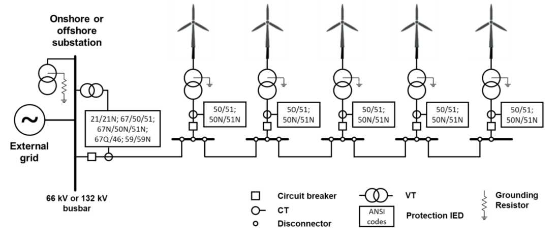
Figure 1 - Standard protection setup for IAC and WTGs
IAC main protection:
- Distance protection (21/21N) with three zones. It is one of the most advanced protection functions and is widely used as a main protection against both multiphase and ground faults for IACs (note that the grounding transformer provides zero-sequence current for ground faults). Zone 1 is normally set up to cover up to 80% of the first section of IAC with instantaneous tripping, whereas Zone 2 covers the whole IAC network and some portion of HV winding of WTG transformers. Zone 3 reaches up to the low voltage (LV) side of WTG transformers. Zones 2 and 3 are time-delayed and coordinated with the WTG protection.
IAC backup protection is implemented in separate hardware and/or in the main protection IED:
- (Directional) phase overcurrent protection (67/50/51) coordinated with WTG protection provides time-delayed backup protection against multiphase and ground faults on IACs. The phase overcurrent protection might include an instantaneous high set stage.
- (Directional) earth fault overcurrent protection (67N/50N/51N) coordinated with WTGs protection provides time-delayed backup protection against ground faults on IACs. The earth overcurrent protection might include an instantaneous high set stage.
- (Directional) negative-sequence overcurrent protection (67Q/46) provides time-delayed backup protection against multiphase faults on IACs and remote backup protection for faults on WTG LV side. The negative-sequence overcurrent protection is coordinated with the WTG protection.
- Zero sequence/phase overvoltage protection (59N/59) is used as a time-delayed protection against uncleared ground faults and system overvoltages.
WTG transformer HV side protection:
- Non-directional phase overcurrent protection (50/51). This protection may include high set instantaneous and time-delayed protection against multiphase faults.
- Non-directional earth fault overcurrent protection (50N/51N). This protection may include high set instantaneous and time-delayed protection against ground faults (as noted above, a grounding transformer provides the zero-sequence current).
Protecting offshore collector networks can be particularly challenging because traditional single-ended protection schemes such as distance and (directional) overcurrent protection may not always be optimized for these applications, leading to potential performance issues. The impacting factors include but are not limited to the infeed from the WTGs located on the faulted cable, capacitive current from all healthy cables, and the resistive nature of the ground fault current if a fault current limiting resistor is used [3]. It should also be noted that all the IAC main and backup protection schemes except distance protection Zone 1 are time-delayed achieving selectivity against WTGs protection.
While the above-mentioned standard protection philosophy for IACs offers an economical solution for most applications, there may be circumstances that necessitate a shift towards other protection schemes, such as differential protection. Several factors could drive this change, including local grid codes and connection agreements that require fast fault clearance in the collector network, which cannot be achieved using time-delayed main and backup protection. Another influencing factor is the need for high sensitivity in the protection system, particularly for faults with low short-circuit currents, and selective discrimination between IAC and WTG faults. Additionally, IAC design constraints may demand rapid fault clearance, which time-delayed protection coordinated with WTG protection cannot provide. In some cases, local regulations may specifically require the application of differential protection for such feeders.
The overall business case is also a critical factor that can influence the protection philosophy of the collector network. The benefits of improved generation and transmission availability, along with IAC design optimization, must be carefully balanced against capital and operational expenditures, the impact on engineering, testing, and commissioning, and the management of interfaces between various project packages necessary for implementing the new protection system design.
3. Protection Using Passive Sensing
3.1. Overview and benefits
Passive sensing offers a robust approach to instrumenting all the remote CTs required for implementing a differential protection scheme throughout offshore networks, using a similar approach as has been demonstrated in transmission systems [4]. Differential protection allows fast fault clearance times. For offshore wind networks, this means that it is possible for every IAC and export cable section to be treated as individual protected sections– enabling granular isolation of faults and fast restoration – without requiring excessive cost. These factors help to minimize damage from faults and maximize the operational revenue from the wind farm.
A passive sensor connects to the secondary of a conventional CT, but no control power or other infrastructure is required at the CT locations. Only optical fiber, which is readily available within the IACs, is required to connect the sensors (which are spliced into an IAC fiber at the termination). Each fiber can multiplex 20-30 sensors operating at different wavelengths, and at various locations as required. Additional fibers can be used to scale this further. An interrogation system located within the onshore or offshore substation centrally accesses all measurements via the fiber. Robust differential current protection is then performed for the individual sections. Should a cable fault for any phase (or combination of phases) on any circuit be identified, the system outputs a trip signal to the local relay for the faulted circuit. In retrofits, this may be achieved via dry contact, IEC 61850 Generic Object Oriented Substation Event (GOOSE) messages, or other protocols to the Main-1 and/or Main-2 relays of the respective circuits. Due to the avoidance of conventional telecoms and the associated communications delays, this approach avoids the infrastructure commonly expected for deploying differential protection schemes. Also, by avoiding latencies associated with a conventional communications channel, the system based on passive sensing is very fast at detecting faults. Reference [4] provides further detail on the operation of the sensor technology.
3.2. Case study string
Figure 1 illustrates one string with five WTGs from a typical offshore wind system. Generally, there could be many strings of turbines spanning from the onshore/offshore substation. More complicated topologies may involve ring structures or interconnections between adjacent strings – with the goal of improving reliability of the collection network and continuity of generation to the grid. The following subsections illustrate how passive sensing can be applied to the case study network. Typical system voltages of 66 kV or 132 kV are shown, but the solution is applicable to any voltage level.
3.3. Option A: “busbar protection” for IAC strings
Option A involves installing CTs at each WTG, and at the offshore substation, as shown in Figure 2. In the case study network, this creates one large multi-ended protection zone, covering the entire string – an arrangement which is equivalent to substation busbar protection, except distributed over many kilometres with subsea cables (therefore requiring provisions for challenges such as cable charging current). The central interrogator performs the required differential protection functionality and issues the trip command.
For strings of five WTGs, protection can be performed using only one interrogator (an interrogator allows measuring currents from 18 single-phase CTs or 6 three-phase CT sets). An efficient method for scaling the system to strings with a larger number of WTGs involves allocating interrogators to implement the protection of just one or two phases, as the protection is performed on a per-phase basis. A phase segregated implementation that uses three interrogators can protect a differential zone with 17 WTGs and connected to one substation, or 16 WTGs connected in a ring between two substations. If necessary, such as to provide external fault detection security logic, coordination can be performed between interrogators via GOOSE messaging or other approaches. Alternatively, in a very large system, one or more interrogators (or other centralized protection IEDs) could be assigned to subscribe to IEC 61850 Sampled Value (SV) streams from other interrogators.
The value of this approach is enabling fast-acting detection and clearance of any faults on IACs or cable terminations. It is not possible to determine the faulted cable or WTG busbar section with this option.
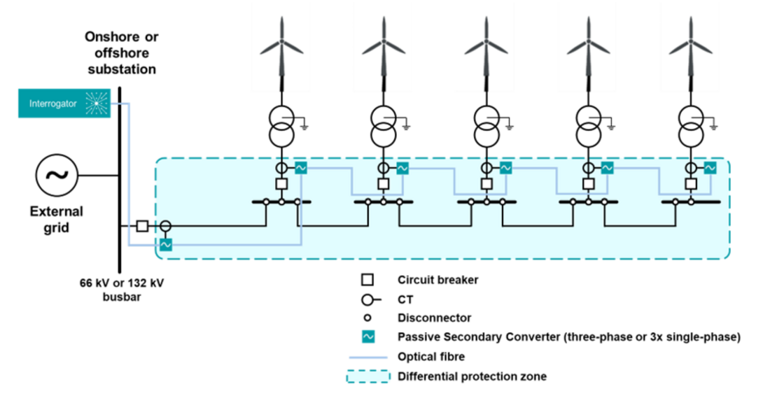
Figure 2 – Option A
3.4. Option B: multi-section protection of IACs and WTGs
For option B, CTs must be installed at both ends of each IAC (and the export cable, if applicable), as shown in Figure 3 and Figure 4. This approach creates multiple protection zones, with one zone covering each IAC. Additional zones can be created around each WTG busbar, as illustrated in Figure 4. A large zone around the entire circuit (i.e. option A) can also be established, which can be used for adding trip security or as a delayed backup zone.
This approach is fully flexible and modular and can scale to any number of IACs/WTGs on the string by adding more interrogators and using more fiber cores. Interrogators are allocated to instrument the required number of CTs.
Unlike Option A, the information from a faulted zone instantly and unambiguously points to the faulted cable or WTG busbar. Although circuit breakers may only be present at the WTG infeed and offshore substation, therefore requiring the entire string to be tripped to clear the fault, the post-fault response can disconnect the faulted zone and then re-energize the unaffected parts of the string. This provides rapid restoration of service for the remaining healthy parts of the system. For ring topologies, typically with a normally-open point (NOP), the NOP position can be dynamically adjusted by controlling disconnectors to further optimize the number of WTGs remaining in service. This approach enables further restoration opportunities if there are additional backup connections between adjacent strings.
The value of option B is fast and selective fault clearance, as well as faulted section identification. This approach also enables discriminative and targeted restoration within protection timescales. Status information from circuit breakers and disconnectors may be required to facilitate optimal post-fault restoration.
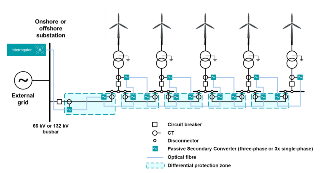
Figure 3 – Option B (showing IAC zones)
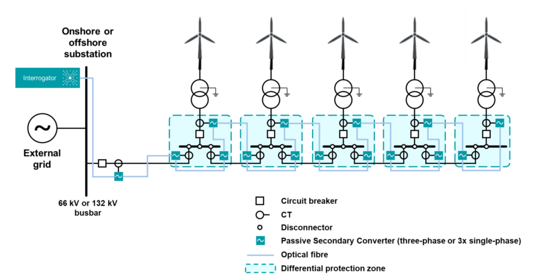
Figure 4 – Option B (showing busbar zones)
3.5. Hybrid and alternative approaches
It is worth noting that a hybrid solution between options A and B is possible, where only the first cable section is instrumented with additional CTs. This ensures that the most critical section, which delivers power from all WTGs on the string, has a dedicated protection zone. The general point is that the solution is flexible, so critical sections of the network can be instrumented and protected with greater granularity to enhance the visibility offered to operators.
Also, option B can be modified to require only two CTs at each WTG – one in the incoming cable and one in the connection to the WTG (see Figure 5). In this arrangement, the WTG bus is included in the differential zone of the outgoing cable. This variant allows reducing the number of installed CTs at the expense of having slightly lower selectivity of faulted section identification (the protection scheme cannot distinguish between the fault at the WTG bus and in the outgoing cable). The reduced faulted section identification problem can be addressed by other means such as a test reclose after reconfiguring the network, assuming the fault is on the cable rather than the bus.
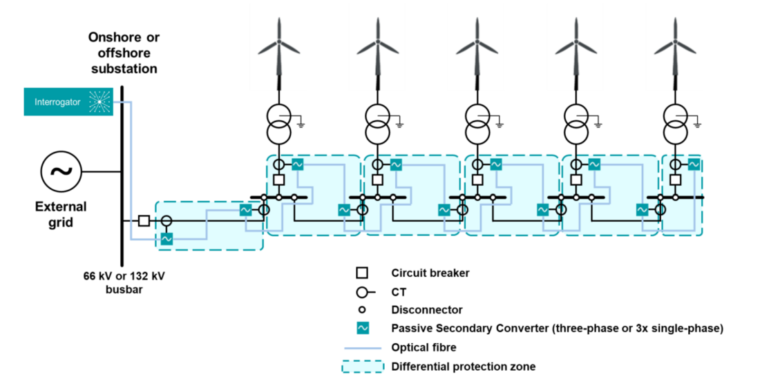
Figure 5 – Alternative option B arrangement with fewer CTs required
4. Comparison and discussion
4.1. Option A vs. B
Table 1 summarizes the main differences between options A and B. The main trade-off is between the cost of additional instrumentation infrastructure, and the benefits offered from fast post-fault restoration – leading to the continuity of supply of renewable generation to the grid. It is also important to note that commissioning and periodic testing/maintenance effort and costs can be significantly reduced for both options A and B. This is because these activities can be performed centrally at the interrogator IED located in the substation, without requiring site visits to the remote WTG locations.
| Parameter | Option A | Option B |
|---|---|---|
| Fast fault detection and clearance | Yes | Yes |
| Granular faulted section identification | No | Yes |
| Ease of post-fault reconfiguration | No | Yes |
| Topologies supported | Any | Any |
| Scalability | Only one interrogator required for moderate string sizes. Additional interrogators deliver per-phase protection for larger systems. | No practical limit on the number of protection zones. Number of interrogators scale simply with number of CTs/zones. |
| Indicative cost | Instrumentation of existing CTs | May require additional CTs for improved granularity |
| Testing and commissioning approach | Performed centrally at interrogator IED in substation | Performed centrally at interrogator IED in substation |
| Maintenance required at CT locations | None after installation | None after installation |
4.2. Comparison with conventional differential protection technologies
The conventional approach to protect multi-terminal systems using differential protection is by deploying multiple relays i.e. one relay at each terminal (or CT location). The relays require a communications channel to transfer current measurements and other data for implementing the required protection functions. The deployment of conventional line current differential systems generally involves data communications links and proprietary data formats. There are also approaches on the market for busbar protection which could be applied to distributed offshore wind cable networks.
The modern implementation of this “brute-force” differential scheme involves installing merging units at each measurement location. A high-performance process bus communications network is critical to ensuring optimal operation – including delivering SV data and distributing time synchronization using the Precision Time Protocol (PTP). Devices are emerging on the market which can subscribe to many SV streams and implement protection functions. The required communications can be readily achieved given the availability of fibers throughout offshore networks.
However, these conventional approaches all require installing powered devices at CT locations, along with supporting infrastructure such as network switches, backup auxiliary power supplies, and time synchronization provisions. While control power will be available within each WTG, routing connections to typical CT locations for IACs could be challenging, particularly when retrofitting existing systems. Therefore, the passive sensing approach described in this paper could reduce the cost, considering the overall business case, and practical deployment concerns for implementing fast-acting, dependable, and sensitive protection of offshore networks. Reducing the installation, testing, and commissioning time is especially advantageous for offshore systems.
Furthermore, conventional differential protection solutions cannot necessarily scale to arbitrary network configurations.
4.3. Integrated solution for offshore protection and control reducing offshore substation space and weight
Further to the approach outlined in Section 3, distributed passive sensing can also form the basis of an integrated platform for protection, control, and condition monitoring of offshore networks. The main advantage is to offer significant savings in offshore substation space and weight. This is because the passive sensing approach is aligned with the centralized protection philosophy allowing a relatively small number of IEDs to perform multiple functions. The interrogators required for a particular implementation can stream SV data to a local centralized protection and control IED which can be configured to deliver all required protection and control functionality. This can dramatically reduce the hardware footprint (i.e. space and weight) required within offshore substations. However, it should be noted that many operators will require to separate protection and condition monitoring functionality, so the system should support “air-gapping” between such functions.
5. Conclusions
This paper has demonstrated that passive sensing is a natural fit for deploying differential protection for offshore wind networks. Differential schemes enable fast and selective fault clearance, which cannot be achieved with overcurrent and distance protection approaches. Differential schemes with multiple differential zones also enable rapid post-fault restoration of the wind farm network to minimize outage time. The presented approaches scale to arbitrary cable and WTG topologies. Similarly, it generalizes for complex feeder protection in sub-transmission networks.
There are additional practical and operational advantages of the approach described in this paper. Passive sensing of CTs saves time during installation, testing, and commissioning, compared to installing conventional relays or merging units which require control power and other infrastructure at measurement locations. In addition to the benefits of fast post-fault reconfiguration, it saves operating expenses (OPEX) because the sensors are not powered and do not require periodic maintenance or reconfiguration, unlike solutions with relays and merging units. This sensing architecture can be combined with cable condition monitoring functions to further enhance the opportunities for managing the health of cables in wind farm networks.
References
- D. Vila, E. Alcázar, J. Juárez, P. Loza, and H.J. Altuve, ‘Protection System for a Wind Generation Plant in Panama: Challenges and Solutions’, presented at the Proceedings of the 42nd Annual Western Protective Relay Conference, Spokane, Washington, 2015.
- IEEE Power System Relaying Committee WG C25, ‘Protection of Wind Electric Plants’, presented at the Proceedings of the 50th Annual Western Protective Relay Conference, Spokane, Washington.
- A. Tsylin, Z. Gajić, and M. Kockott, ‘Optimization of Distance Protection Performance Used In Wind Farms’ Collection Networks’, presented at the Proceedings of the 49th Annual Western Protective Relay Conference, Spokane, Washington, 2022.
- B. Kasztenny, S. Blair, N. Gordon, P. Orr, and C. D. Booth, ‘Solving Complex Feeder Protection Challenges and Reducing Wildfire Risks With Remote Measurements’, in 50th Annual Western Protective Relay Conference, Spokane, Washington, 2023.
- CIGRE B1 WG B1.60, ‘Maintenance of HV Cable Systems’, CIGRE B1, Technical Brochure 825, 2021.