Multivendor Interoperability Tests for Process Bus in Japan based on International Standards
Authors
Kota KAWASAKI, Masayuki DEGUCHI - Central Research Institute of Electric Power Industry, Japan
Makoto OKAI, Takeshi ASAI - Toshiba Energy Systems & Solutions Corporation, Japan
Keigo SHIMOFUJI, Shotaro SHIROI - Hitachi, Ltd, Japan
Yasutaka KATAYANAGI, Akifumi IWAMARU - Mitsubishi Electric Corporation, Japan
Keiichi NAGATA, Yuta ISHIGAMI - Fuji Electric Co., Ltd, Japan

Summary
The implementation of a process bus for digital signal transmission between Intelligent Electronic Devices (IEDs) and merging units (MUs) significantly reduces cabling requirements and streamlines installation processes. To maximize the effectiveness of the process bus in substations while ensuring interoperability, adherence to IEC 61850 and IEC 61869 is crucial. However, variations in the interpretation and application of these standards by different vendors can lead to interoperability challenges. Consequently, the Central Research Institute of the Electric Power Industry (CRIEPI) is developing functional specifications to define common and effective application methods of IEC 61850 for process buses, specifically for Transmission System Operators (TSOs) in Japan. The challenges related to processing and communication during the operation of actual devices must be identified for the functional specifications through interoperability testing involving real IEDs and MUs.
This study details the interoperability tests conducted on a process bus comprising four distinct types of IEDs and six varying types of MUs from multiple manufacturers. The interoperability tests focused on evaluating the sampled value (SV) messages transmitted from the MUs and the corresponding receiving processes within each MU. The evaluation included a comparative analysis of waveforms transmitted in SV messages representing the same source of current and voltage signals. Functional tests were conducted for major substation operations, including measurement, circuit breaker control, monitoring, and protection.
The initial test results revealed discrepancies in the phases derived from the transmitted waveforms across various MUs. To address this issue, we clarified the methodology for assigning the smpCnt attribute value to SV messages. This adjustment resulted in a reduction of the observed phase differences.
However, during the reception of SV messages, certain IEDs failed to read SV messages from specific measurement variables. This issue originated from compatibility discrepancies; certain MUs and IEDs conformed to broader specifications for SV services (IEC 61850), while others adhered to the more specialized requirements for instrument transformers (IEC 61869-9). Upon recalibrating the MU settings to align with IEC 61869-9, a marked increase in successful IED–MU interactions was observed.
In the circuit-breaker control test, certain combinations of IEDs and MUs did not facilitate control. The findings underscored the urgent need to clarify the implementation points for the Select function, specifically at the bay-level process and the timing of data object transmissions via generic object-oriented substation events (GOOSE). In the future, to improve interoperability and mitigate engineering efforts, it will be crucial to either expand the values of the control model by considering extensions to the process bus or to introduce new data objects to manage these extensions.
As a result of the protection function test, the total duration from fault current detection to trip coil activation was recorded to be between 20 and 40 ms, demonstrating its capacity to meet general user requirements. Future developments will integrate enhancement strategies derived from these findings into functional specifications, finalized through continuous desk studies and testing. If necessary, results will be incorporated into international standards.
Keywords
Substation, Interoperability, Process bus, Multivendor1. Introduction
A process bus efficiently transmits digital signals between intelligent electronic devices (IEDs) and merging units (MUs). This approach minimizes the number of cables and streamlines the installation process. To maximize the effectiveness of the process bus in substations while ensuring interoperability, adherence to IEC 61850 and IEC 61869 is paramount. However, variations in the interpretation and application of these standards by different vendors can result in interoperability issues.
IEC 61850-7-500 [1] provides guidelines for the implementation of protection, automation, and control (PAC) functions in digital substations based on the IEC 61850 series. Nevertheless, these guidelines may be insufficient to address the requirements of transmission system operators (TSOs) in Japan. In contrast, other countries have published functional specifications through organizations such as the Electric Power Research Institute (EPRI) in the United States and Réseau de Transport d'Électricité (RTE) in France [2][3]. Furthermore, although the UCA conducts international interoperability tests to ensure multivendor compatibility, these tests may not adequately address the unique functional requirements of Japanese TSOs. Consequently, the development of tailored functional specifications and interoperability tests is essential for domestic applications in Japan.
In response to these challenges, the Central Research Institute of the Electric Power Industry (CRIEPI) is actively engaged in creating functional specifications that define standardized and effective application methods for the IEC 61850 process bus, specifically designed to meet the needs of TSOs in Japan. A collaborative research project involving TSOs and vendors is currently underway to achieve higher-quality functional specifications. In this context, various challenges may arise from processing and communication within actual devices. Thus, these challenges need to be addressed through interoperability testing employing actual IEDs and MUs, while also exploring improvement methodologies as stipulated in the functional specifications.
This research details multivendor interoperability tests related to a process bus, encompassing four distinct types of IEDs and six different types of MUs currently offered by both Japanese and international manufacturers. The tests primarily focused on the sampled value (SV) messages originating from the MUs, including a comprehensive analysis of current and voltage waveforms derived from these SV messages, alongside an assessment of SV message reception across each IED. Furthermore, PAC functional tests were performed to evaluate critical substation operations, including measurements, circuit breaker control, monitoring, and protection functionalities.
The remainder of this paper is organized as follows: Section 2 delineates the configuration and methodology employed in the test system; Section 3 presents the results of the tests along with a discussion; and Section 4 provides the conclusions and outlines plans.
2. Test System Configuration and Test Methodologies
2.1. Test System Configuration
The configuration of the test system is illustrated in Figure 1, which incorporates four types of IEDs and six types of MUs sourced from both Japanese and international manufacturers. The test system is further augmented by a precision time protocol (PTP) master, a simulator for current transformers (CT)/voltage transformers (VT), and a circuit breaker. The analog signals (e.g., current, voltage, and circuit breaker status) from the simulator were connected to the MUs to establish a comprehensive evaluation framework. An optical cable network, complemented by an L2 switch, was implemented to facilitate the transmission of sampled values (SV) and generic object-oriented substation events (GOOSE) messages between the MUs and IEDs. SV messages are transmitted from the MUs to the IEDs, providing real-time data on current and voltage levels. Conversely, GOOSE messages are transmitted independently in each direction: from the IEDs to the MUs for circuit breaker operation requests and from the MUs to the IEDs for circuit breaker status information.
In this study, the manufacturers of the IEDs and MUs are designated as Company A–F, as the focus is not on product evaluation but rather on the integration of prototype devices from each manufacturer. The test system incorporates several additional devices, including an L2 Switch, a PTP Master, a simulator for CT/VT/Circuit Breaker (hereafter referred to as the CT/VT/CB Simulator), an IEC 61850 Client Tool on the Test PC, and an SV Analysis Tool on the Test PC. The specifications for each company's MUs are detailed in Table 1, whereas Table 2 outlines the specifications of the IEDs. These specifications informed the design of the test methodology and the development of test cases.
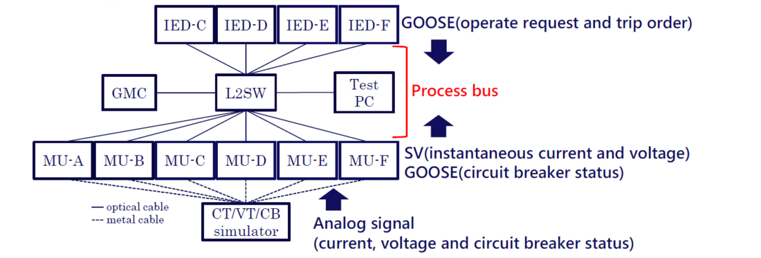
Figure 1 - Test System Configuration
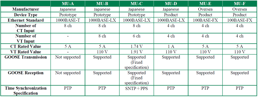
Table 1 - Specifications of MUs under the Tests

Table 2 - Specifications of IEDs under the Tests
2.2. Test Cases
The process bus system leverages both GOOSE and SV messages, and the operational requirements for GOOSE messages have been defined in previously established functional specifications. In contrast, the specifications regarding the utilization of SV messages represent a novel addition specifically designed for the process bus. Therefore, the initial step involves verifying the SV messages.
In the subsequent phase of the study, comprehensive functional tests were executed. The functional specifications for the process bus encompass seven typical use cases relevant to PAC functions: measurement, circuit breaker control, monitoring, protection, breaker failure protection, interlocking, auto-reclosing, and synchro check. These use cases were developed to address the specific operational requirements of domestic substations. This research primarily focuses on four key functions: measurement, circuit breaker control, monitoring, and protection.
2.2.1. SV Message Test Cases
2.2.1.1. Communication Profile of SV Message
According to the international standard IEC 61869-9 Ed. 1.0 [4], which articulates the detailed requirements for the digital interface of MUs, the communication profile for SV messages is characterized by a combination of four parameters. There are the sampling Rate (f), number of application service data units (ASDUs) in SV messages (s), number of data points for current (i), and number of data points for voltage (u). The selection criteria and corresponding values for these parameters in the context of this test are as follows:
- f: IEC 61869-9 Ed. 1.0 stipulates a recommended sampling rate of 4800 Hz for both 50 Hz and 60 Hz systems, as detailed in Table 3. In contrast, JEC-2502, a standard for analog-todigital converters specifically designed for protection relays in Japan [5], prescribes a standard sampling rate of 4800 Hz for 50 Hz systems and 5760 Hz for 60 Hz systems. In this context, a significant number of the Japanese MUs utilized in this test complied with the JEC-2502 standard, as detailed in Table 4. Therefore, the sampling rate was set at 4800 Hz and 5760 Hz for the 50 Hz and 60 Hz systems, respectively. Although the CT/VT/CB Simulator is not classified as an MU, it can generate SV messages for comparative analysis.
- s: Each ASDU contains the key parameters of the SV message, along with sampled data for current and voltage. Multiple ASDUs, accompanied by their corresponding header information, collectively form an application protocol data unit (APDU) transmitted as an SV message. Currently, no Japanese standards exist for this process, as JEC-2502 focuses only on the sampling rate for analog-to-digital conversion. As presented in Table 3, IEC 61869-9 Ed. 1.0 recommends setting the number of ASDUs related to measurement and protection to 2. However, due to the compatibility of the equipment utilized in our experiment, the ASDU value was configured to 1, as indicated in Table 4.
- i and u: Each SV message contains four current and four voltage data points per ASDU and are assumed to represent a three-phase, four-wire system. However, as listed in Table 1, an SV message from MU-A contains only eight current data points without any voltage data, as it does not feature any voltage measurement channel.
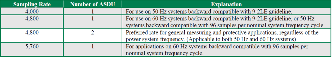
Table 3 -Standard sampling rates and numbers of ASDUs (extract from IEC 61869-9 Ed. 1.0 Table 902)
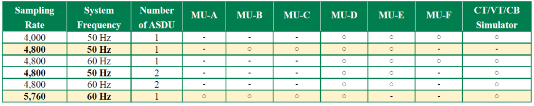
Table 4 - Sampling rates and numbers of ASDUs of the MUs (JEC-2502 is marked in Bold, tested Items are
highlighted)
2.2.1.2. Tests and Evaluation Methodologies of SV Messages
SV messages, which contain instantaneous current and voltage values, were dispatched from each MU. The resultant current and voltage waveforms were subsequently plotted and analyzed on a Test PC. Furthermore, the capability of each IED to read SV messages was thoroughly validated.
During the testing phase, analog signals of the same phase were interfaced with the MUs. To ensure identical amplitudes, the line-to-line voltage applied to devices, excluding MU-C, was set to 110 V, while the phase current was established at 1 A, and adjusted to align with the lower-rated MU-D. For the MU-C configuration, the analog signals were calibrated to 1.91 V for voltage and 0.348 V for current.
To facilitate the analysis of the SV messages transmitted from each MU to the PC, the SV Analysis Tool was utilized. The smpCnt attribute served a pivotal role in comparing the recorded current and voltage values. This smpCnt value, an integral component of the SV messages, initiates at 0 at the commencement of each second and increments by 1 for every sample taken. With a sampling rate of 4800 Hz, the smpCnt value ranges from 0 to 4799, resetting to 0 at the beginning of the subsequent full second after reaching its maximum.
Assuming precise time synchronization among the MUs, the identical-phase and identicalamplitude analog signal inputs for current and voltage can be expected to produce the corresponding identical phase and amplitude values for the same smpCnt. To analyze the relationship, current and voltage values were organized according to smpCnt, followed by a mathematical fitting process utilizing the subsequent formula. This process facilitated the determination of the current or voltage amplitude (a), sampling angle (b), phase angle (c), and offset (d) variables, which were essential for reconstructing the AC current and voltage waveforms.
a cos (b smpCnt + c) + d. (1)
The CT/VT/CB Simulator is capable of generating SV messages concurrently with analog outputs, thus rendering it well-suited for comparative analysis. However, as illustrated in Table 4, the CT/VT/CB Simulator is unable to produce SV messages at a sampling rate of 4800 Hz with a single ASDU for a 50 Hz system. Consequently, SV messages from the MU-E were employed for comparison within the 50 Hz system. As previously confirmed, the phase and amplitude errors between the SV message outputs from MU-E and the CT/VT/CB Simulator were negligible.
To assess the capabilities of each IED in reading SV messages, a test was conducted with a sampling rate set at 4800 Hz for the 50 Hz system, adhering to the specifications of each device. The various combinations tested are enumerated in Table 5.
2.2.2. PAC Function Test Cases
This study concentrated on four use cases: measurement, circuit breaker control, monitoring, and protection. For each use case, detailed sequence diagrams were developed, which illustrated the flow of SV and GOOSE messages and the interactions with the primary circuit, the internal data processing exchanges, as well as the logical nodes and data objects utilized during these exchanges. The sequence pertaining to circuit breaker control (Figure 2) is select-beforeoperate control, extended to process level using GOOSE. The decision to extend the select and operate test functions to the process level is contingent upon user requirements; thus, their incorporation remains optional. Nonetheless, both functions were included in the testing process to ensure a thorough verification scope. The target devices utilized for the circuit breaker control tests are detailed in Table 6. The test method encompassed the following steps to evaluate the behavior of the devices while performing operations No.1.0 and No.2.0, as illustrated in Figure 2, using Client Tool.
- Responses transmitted from the IEDs were captured utilizing the Client Tool.
- The values obtained from various instances of the IED/MU were sourced either through Client Tool or via the engineering tools provided by each vendor.
- GOOSE messages circulating within the network were documented through packet capture techniques.
- The operational state of the primary circuit simulator was acquired using its dedicated operational and monitoring tools.
In parallel, the methodologies for measurement, monitoring, and protection were established based on the relevant sequence diagrams and the compatibility specification of the target devices.
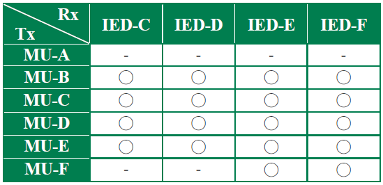
Table 5 - Test subjects for SV messages reception
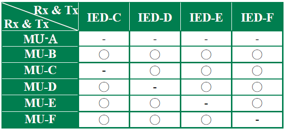
Table 6 - Test subjects for circuit breaker control
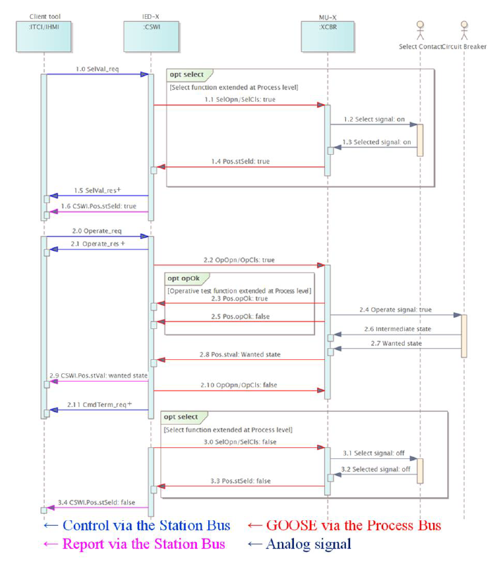
Figure 2 - Sequence diagram for CB control
3. Tests Result and Discussion
The engineering and interoperability testing progressed through a systematic three-step process:
- Exporting Substation Configuration Language (SCL) files: Domestic manufacturers configured their devices locally, while the CRIEPI configured overseas devices. Each device was configured using its respective IED Configuration Tool (ICT), and the Configured IED Description (CID) or Instantiated IED Description (IID) files were subsequently exported.
- Importing SCL files: Each device successfully imported the corresponding CID or IID files from its counterparts to finalize the settings for SV and GOOSE message reception by using System Configuration Tool (SCT) and the ICT.
- Interoperability testing: An extensive interoperability test was conducted over five days at the CRIEPI facility. This testing involved approximately 30 participants, including design and development engineers from various manufacturers, while representatives from TSOs observed the proceedings.
3.1. SV Message Test Results
3.1.1. SV Message Comparison and Improvements
The initial comparative analyses of the current and voltage waveforms extracted from the SV messages on the PC revealed notable phase discrepancies between the MUs, as illustrated in Figure 3.
Subsequent investigation into the cause confirmed that the phase difference can be improved using the following approach:
- Ensuring Accurate Correspondence Between “smpCnt” and Sample Data in SV Messages: To ensure that the “smpCnt” attribute values accurately reflected the temporal points of the analog signal input, compensation for the processing delays inherent within the MUs was performed. This compensation aligned with the guidelines stipulated in IEC 61869-9 Annex 9 B.
An enhanced example incorporating these corrections is illustrated in Figure 4, and the aggregated results for all target MUs are summarized in Table 7.
The phase difference was calculated using values derived from Equation (1), with the CT/VT/CB Simulator or MU-E serving as the reference point against the measurements obtained from MUs produced by manufacturers A through D. A notable maximum phase difference of 1.64° was recorded. Currently, compensation is implemented on a per-samplingperiod basis, meaning phase correction implemented in increments of the sampling angle by 3.75°, which is calculated as 360 × (system frequency / sampling rate. Future enhancements are anticipated through the design of the MU, ensuring that the internal processing time is an integer multiple of the sampling period. This adjustment is expected to facilitate more accurate phase alignment.
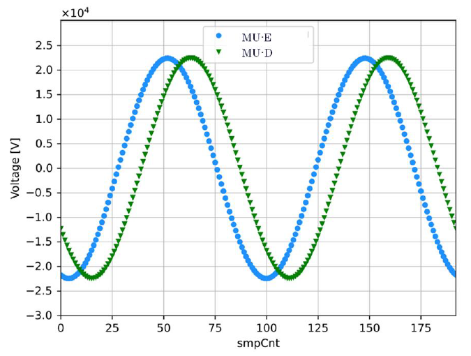
Figure 3 - Initial comparison of voltage waveforms
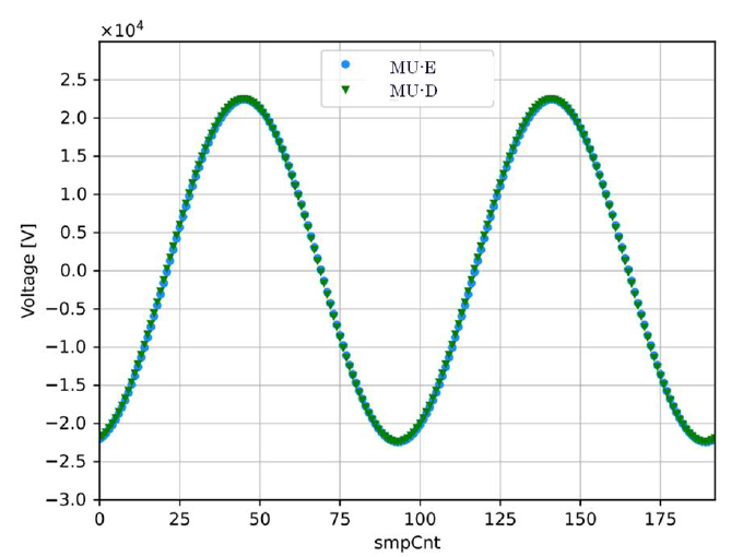
Figure 4 - Comparison of voltage waveforms after improvement
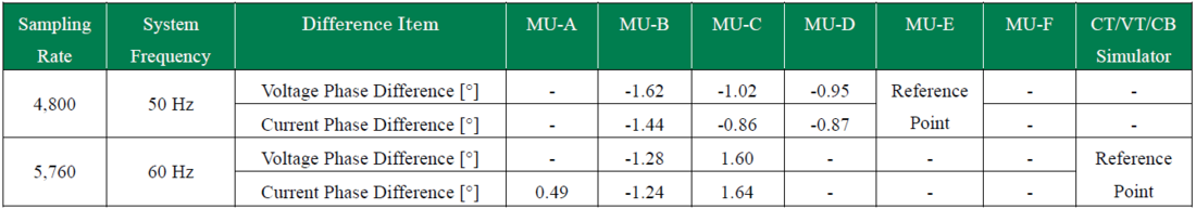
Table 7 - Differences for MUs after improvement
3.1.2. SV Message Reception in Each IED
The verification results regarding the reception of SV messages across each IED indicate that certain combinations of IEDs and MUs initially encountered difficulties in successfully reading the SV messages. As summarized in Table 8, only 9 out of the 18 potential combinations of IEDs and MUs accurately read the SV messages. The causes of unread messages are listed as follows:
- Minor software bugs
- Reception issues attributed to differences in compatibility, as some MUs and IEDs adhered to the general specifications for SV services in IEC 61850, whereas others followed the more specific requirements for instrument transformers in IEC 61869-9. The distinctions between IEC 61850 and IEC 61869-9 are outlined in Table 10.
The functional specifications for this study were predicated on the implementation of SV services for instrument transformers. Consequently, the OptFlds and the organization of data within the SV messages were meticulously revised to ensure conformity with IEC 61869-9 standard. Following a comprehensive retest, five additional combinations successfully processed the SV messages, as detailed in Table 9.
However, in the four remaining combinations, constraints associated with the prototype, along with other limitations, impeded full adherence to the IEC 61869-9 specifications. Nevertheless, further enhancements are anticipated to facilitate complete compliance with this standard.
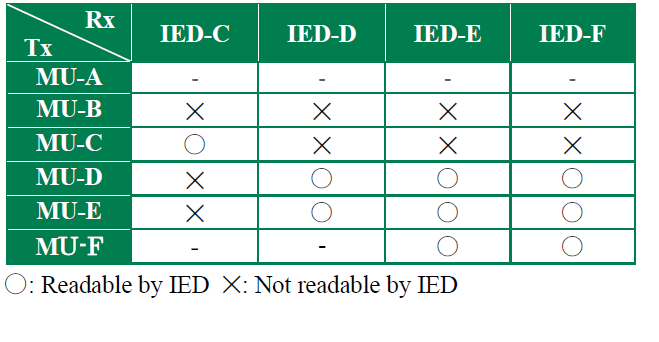
Table 8 - Result for SV messages reading
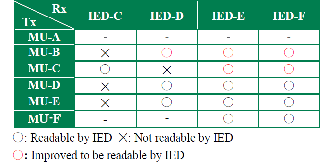
Table 9 - Result for SV messages reading after improvement
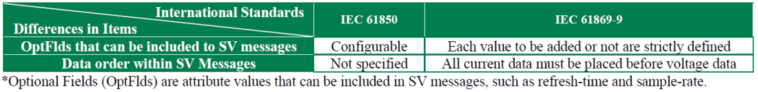
Table 10 - Difference between IEC 61850 and IEC 61869-9
3.2. PAC Function Test Results
The testing protocol included specific use cases across four critical domains: measurement, circuit breaker control, monitoring, and protection. A summary of the test outcomes follows:
3.2.1. Measurement
In instances where the IED successfully read the SV messages, the measurement functionality operated seamlessly.
3.2.2. Circuit Breaker Control
Conversely, during the initial testing phase, the circuit breaker control encountered failure in the combination involving the domestic MU-B and the overseas IED-F.
This failure was attributed to the simultaneous execution of Step No. 2.2 and Step No. 3.0, as illustrated in Figure 2 for IED-F. This testing phase confirmed that the issue could be rectified by adjusting the internal logic of the domestic MU-B. Furthermore, additional verification is necessary to assess whether user-configurable engineering modifications can ensure that IEDF adheres to the sequence outlined in Figure 2.
This result highlights the need to clarify the implementation points for the Select function at both the process and bay levels as well as the timing of each data object transmitted via GOOSE. The Control model outlined in IEC 61850-7-2 Ed.2.1 and IEC 61850-7-3 Ed.2.1 primarily emphasizes control through the MMS, which can be precisely defined and configured based on its values [6][7]. The relationships between various control model values and their corresponding models are succinctly summarized in Table 11. In contrast, IEC 61850-7-500 illustrates how circuit breaker control can be extended to the process level using GOOSE messages. However, the control model values do not provide explicit definitions or configurations regarding the type of control—specifically, whether it involves select-beforeoperate control or direct control—when extending functionality via GOOSE messages.
Therefore, user engineering including the implementation of tools such as PLC logic is currently necessary. In the future, to improve interoperability and mitigate engineering efforts, it will be crucial to either expand the values of the control model by considering extensions to the process bus or to introduce new data objects to manage these extensions. This strategy permits flexibility, enabling users to extend functions such as select and operate test functions to the process level based on specific user requirements. Ideally, these functionalities should be defined and configured independently to facilitate customization by users.
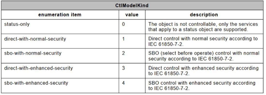
Table 11 - Literals of CtlModelKind (extracted from IEC 61850-7-3 Ed.2.1)
3.2.3. Monitoring
Furthermore, the monitoring function has been demonstrated to operate effectively without issues.
3.2.4. Protection
The protection mechanism was assessed using an overcurrent relay, with the total duration from the detection of fault current to the activation of the trip coil recorded between 20 and 40 ms. This result highlights the capability of the system to effectively fulfill general user requirements.
4. Conclusions
This study presented a testing process that entailed a comprehensive evaluation of ten protection and control devices sourced from four domestic manufacturers and two international suppliers. A meticulous test environment was established, taking into account a thorough understanding of the specifications of each device. The test cases were systematically categorized into two primary categories:
- Tests related to SV messages
- Tests associated with PAC functions
In the SV message tests, instantaneous current and voltage data were transmitted via SV messages from each MU. These messages were chronologically plotted on a PC for waveform analysis, and the ability of each IED to accurately read the SV messages was confirmed.
To facilitate waveform comparison, phase discrepancies were mitigated by compensating for the processing time within the MU, ensuring that the sample count attribute (smpCnt) values accurately reflected the corresponding time point of the analog signal input.
During the verification of SV message readability, certain combinations of devices initially encountered challenges in message reception. This issue was resolved by adjusting the MU settings to ensure compliance with IEC 61869-9 standard.
In the PAC function tests, specifically during circuit-breaker control assessments, several combinations of IED/MU pairs initially failed to operate as anticipated. This outcome highlights the significant shortcomings of existing standards, especially regarding the definition and execution of control sequences when extending control to the process level via GOOSE Messages.
The improvement methods presented in this study will be reflected in the functional specifications, establishing them as common specifications for the application of process buses in domestic substations. Furthermore, these specifications will undergo additional refinement through continuous desk-based research and interoperability testing that incorporates insights from Japanese TSOs. Currently, functional specifications that incorporate additional advanced functionalities, such as auto-reclosing, breaker failure protection, and busbar protection, are being developed. Simultaneously, the classification of the test cases for these advanced functionalities is being planned. While these approaches specifically focus on addressing the requirements of the Japanese TSOs, which are not explicitly covered in the international standards or UCA’s interoperability tests, key findings will be evaluated for potential integration into international standards.
References
- IEC 61850-7-500 Edition1.0 “Communication networks and systems for power utility automation – Part 7-500: Basic information and communication structure – Use of logical nodes for modeling application functions and related concepts and guidelines for substations” (February 2017).
- P. Myrda, H. Falk. “Common Substation Platform: Utility Requirements Assessment – Part 1.” (January 2022).
- V. Leitloff, G. Duverbecq, Y. Leloup, J.E. Lemaire, F. Fousseret. “Rte Substation Protection Automation and Control Systems IEC 61850 Model.” (June 2020).
- IEC 61869-9 Edition 1.0 “Instrument transformers – Part 9: Digital interface for instrument transformers” (April 2016).
- Standard of the Japanese electrotechnical committee JEC-2502-2010, "Analog to digital converter dedicated to numerical relays" (May 2010). (in Japanese)
- IEC 61850-7-2 Edition2.1 “Communication networks and systems for power utility automation – Part 7-2: Basic information and communication structure – Abstract communication service interface (ACSI)” (February 2020).
- IEC 61850-7-3 Edition2.1 “Communication networks and systems for power utility automation – Part 7-3: Basic communication structure – Common data classes” (February 2020).