Sensitive Turn-to-turn Fault Protection for Power Transformers Using Incremental Negative-Sequence Differential and Advanced Stabilising Criteria
Authors
Frank MIESKE, Sebastian SCHNEIDER - Siemens AG, Germany
Waldemar REBIZANT, Krzysztof SOLAK - Wroclaw University of Science and Technology, Poland

Summary
The paper presents a novel sensitive turn-to-turn fault protection scheme for power transformers based on incremental negative-sequence differential current. A CIGRE survey on transformer reliability reveals that 49% of transformer failures were winding faults. Due to the high short-circuit current inside the short-circuited turns, the undetected turn-to-turn fault (TTF) can lead to severe external consequences such as explosion, burst and fire. For these reasons, in the event of an incipient turn-to-turn fault in the power transformer, it is necessary to disconnect the faulty transformer immediately in order to prevent the fault from spreading and causing major irreparable damage and a loss of customer service. On the other hand, the power transformer protection must not operate in other operating and switching conditions, as an unplanned disconnection of a power transformer in a central node can lead to cascading failures. Since the fault currents that can be measured at the terminal are small, the detection of TTF faults in power transformers is a serious protection challenge. Present protection schemes based on negative-sequence differential current are briefly presented and discussed, as the proposed method represents a further development of these methods.
The novel sensitive turn-to-turn fault protection is based on determining the incremental negative-sequence differential current between the pre-fault and fault state. For reliable discrimination of TFFs from adverse conditions, the restraint quantity in an operating percentage characteristic and two novel powerful stabilisation criteria have been proposed.
The novel vectorial similarity criterion effectively discriminates turn-to-turn faults from inrush or overexcitation conditions. The second powerful criterion is the zero-sequence differential current that ensures security in a case of false differential current during external faults, especially generated by iron-core current transformers (CT) due to remanence and CT saturation. The paper demonstrates the superior performance in terms of dependability and security of the proposed protection scheme by discussing selected transients of TTFs, evolving TTF in the presence of an external fault and external faults obtained with a Real-Time Domain Simulation (RTDS) model of an autotransformer in a high-voltage network. The novel sensitive turn-to-turn fault protection complements the transformer differential protection in a modern protection IED. The multi-functional modern IED with enhanced processing power enables the optimum protection scheme with different protection functions for the power transformer. The individual protection function is specialised for specific fault types and is more sensitive and secure.
Keywords
Transformer protection, Turn-to-turn faults, Incremental negative-sequence differential current protection1. Introduction
Power transformers are critical components in electrical power systems, both in terms of their role in the power system and their cost. A study of transformer failures in [1] revealed that the most common components to fail were the windings (34%), the bushings (14%), the on-load tap-changer, OLTC (10%) and the de-energised tap-changer, DTC (10%). The CIGRE Transformer Reliability Survey [2] reported that approximately 50 % of major failures occur in the transformer windings. The degradation of a transformer's insulation system over the years of service is the main factor leading to electrical faults in the windings or turn-to-turn faults (TTF). The undetected turn-to-turn fault (TTF) can lead to external consequences such as explosion, burst and fire due to the high short-circuit current in the short-circuited turns Therefore, in the presence of an incipient TTF in the power transformer, it is important to have a reliable protection scheme to immediately disconnect the faulty transformer from the power system and prevent the fault from spreading and causing major, irreparable damage and loss of supply to customers. On the other hand, this protection scheme must not operate under other operating and switching conditions, as an unplanned shutdown of a power transformer in a central node can lead to cascade failures.
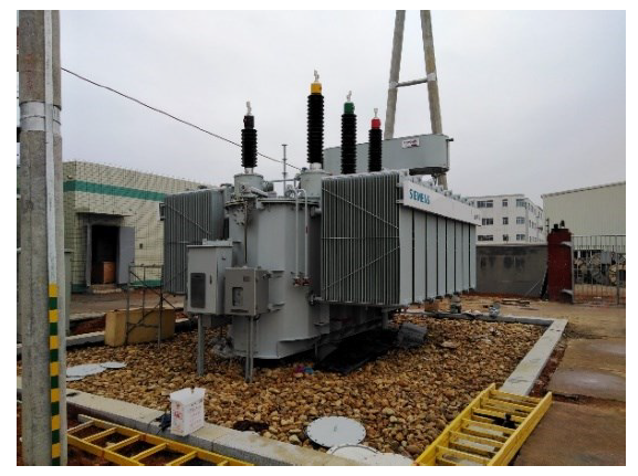
Figure 1 - Power transformer
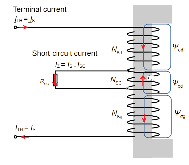
Figure 2 - TTF modelled as an auto-transformer winding
The shorted turns can be considered as a separate winding, similar of an autotransformer common winding shown in Figure 2. A very high short-circuit current, driven by the electromagnetic force (EMF), flows through the shorted turns. Due to the ampere-turn balance, the fault current is transformed into the terminal current by the ratio of the short-circuited turns and the intact turns of the winding. The authors of [3] calculated the lowest currents for TTFs between parallel conductors and with a short-circuit resistance. In fact, a small fault resistance will even significantly reduce the measured terminal fault current.
The transformer differential protection with the percentage characteristic is the most commonly used TTF protection scheme, besides gas actuator systems such as the Buchholz or sudden pressure relays. Based on Kirchhoff’s law, it has inherent selectivity. However, the essential percentage characteristic limits the sensitivity. The TTF changes the ampere-turn balance of the transformer. Therefore, the standard transformer differential protection (ANSI 87T) is in principle able to detect TTFs. However, if only a small number of windings are short-circuited, only a small change in current is measured at the terminals. It has been shown that for such types of TTFs, the differential current of the transformer differential protection is well below the operating threshold, and the transformer differential protection cannot reliably detect them. The report in [4] shows the transient of a real TTF in an autotransformer tripped only by the Buchholz relay.
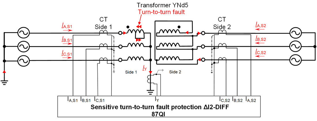
Figure 3 - Fault current distribution for a TTF in the star-connected winding of a YNd5 power transformer
Due to the low dependability of the standard transformer differential protection in detecting TTFs, new protection schemes have been developed for sensitive Turn-to-turn Fault (TTF) protection, mainly based on the negative-sequence current and negative-sequence differential current. In the following, these schemes are briefly described and discussed on the basis of a study in [5] on the reliability of TTF protection systems in power systems with inverter-based resources. The well-established standard transformer differential protection, based on the equality of the ampere-turns and the Kirchhoff current law, forms the operating quantity or differential current ??? of phase x, as the absolute value of the sum of the magnitude and vector group compensated transformer side phasors.
The Negative-sequence Differential (87Q) concept [6] implemented in the protection relay [7] also follows the current differential principle but applies it to the calculated negative-sequence differential currents of the transformer sides. The operating quantity, the negative-sequence differential current ?2? is the sum of the negative-sequence transformer side currents, which are formed from the magnitude- and vector-group compensated transformer side current phasors using the Fortescue transformation. The restraining quantity is the sum of the absolute values of all negative-sequence side currents. The 87Q protection operates when the negative-sequence differential current is above a fixed pickup threshold and a slope of the restraining current. The developers of the 87Q protection in [8] point out that the negative-sequence differential current is more suitable for discriminating TTF than standard differential current protection since the negative-sequence differential current is almost zero under through load flow and is relatively independent of the magnitude of the load flow.The so-called Sensitive Negative Sequence Differential Protection (SNSDP) [4] implemented in the protection relay [9] is not a negative-sequence differential protection scheme. It examines the angle between the ratio and vector group compensated negative-sequence current phasors of both transformer sides. The author in [10] has observed only a marginal improvement in the sensitivity of 87Q and SNSDP compared to the standard transformer differential protection. An investigation of the dependability of TTF protection schemes based on negative-sequence differential current in power systems with inverter-based resources (IBR) in [5] showed the suitability of the 87Q protection scheme for detecting TTFs. However, directional protection systems such as SNSDP based on negative-sequence current have low dependability in power systems with a high amount of IBRs.
The percentage-based fault-related incremental current method [11], [12] abbreviated as 87Q FRIC, evaluates the increments of the positive- and negative-sequence differential current during TTF to the pre-fault condition. The incremental quantities are also known as Deviation of Power System Frequency Components or Delta Quantities. The report [5], concluded that the incremental negative-sequence differential current protection (87Q FRIC) provides the highest sensitivity. However, some weaknesses have been identified in a security examination.
Consequently, improvements are necessary for the 87Q and 87Q FRIC TTF protection schemes in terms of security in the event of external faults with current transformer (CT) saturation and other reasons for false differential currents.
2. Algorithm of the Proposed Incremental Negative-Sequence Sensitive 87QI TTF Protection Scheme
2.1. Principle of the Protection Scheme
The operating quantity of the proposed incremental negative-sequence differential current is formed as the absolute difference between the latest negative-sequence differential current and the pre-fault negative-sequence differential current
calculated as follows:
(1)
Figure 4 shows the principle of incremental processing. A complex phasor subtraction extracts the fault-related negative-sequence differential current phasor from the pre-fault and the most recent phasors. The pre-fault phasor is shifted by one cycle of the power system frequency before. During a fault, the pre-fault phasor is latched. The pre-fault false negative-sequence differential current is caused under normal conditions by CT accuracy errors and the magnetising current. The incremental negative-sequence differential current phasor enables a low threshold for high dependability and the incremental positive- and zero-sequence differential current phasors enable advanced new stabilisation criteria to ensure high security.
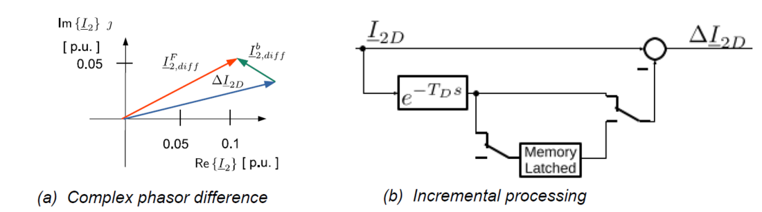
Figure 4 Determination of the Incremental Negative-Sequence Differential Current Δ3?2,????
The logic of the proposed incremental negative-sequence current differential protection is shown in Figure 6. The measurement-preprocessing of differential quantities is based on the standard differential protection measurement-preprocessing. The scheme includes blocks for fault detection and incremental processing. An operating limit block restricts the operating range. The stabilisation criteria also include inrush blocking based on Current Waveform Analysis (CWA).
2.2. Percentage Incremental Restraint Characteristic
A percentage incremental characteristic stabilises the incremental negative-sequence differential turn-to-turn fault protection. The restraint quantity is also based on an incremental quantity. A sum TrueRMS value ?ΣTrRMS x for each transformer winding (x) is calculated as the sum of the three phase TrueRMS values. The incremental TrueRMS sum transformer side current is then formed as the difference between the most last TrueRMS value ?ΣTrueRMS ? and the one before the fault:
(2)
Finally, the incremental restraint quantity Δ?? is obtained as the maximum incremental transformer restraint current of all transformer sides of a multi-winding power transformer or breaker-and-half arrangements:
(3)
The required incremental negative-sequence differential current is increased according to the incremental restraint quantity Δ?? . The characteristic curve is used to stabilize for false incremental differential currents under normal operating conditions due to switching, tapchange operations and load jumps.
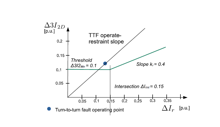
Figure 5 - Percentage Incremental Restraint Characteristic
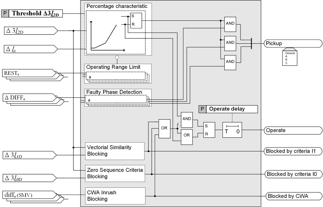
Figure 6 - Incremental Negative-sequence Differential Current Protection
shows the percentage incremental characteristic and its parameters. The horizontal curve represents the sensitivity threshold, which is configurable by the customer and has a default value of 0.1 p.u. The slope of 0.4 is a non-configurable internal setting, as there is no specific power system dependency.
2.3. Novel Add-on Stabilisation Criteria
In the case of non-linear CT faults or non-linear transformer magnetising currents, additional stabilisation is essential to ensure safety at this high sensitivity. The mathematical correlation of the positive-, negative- and zero-sequence differential current for TTF fault currents has been derived analytically using the Thévenin equivalent circuit and provides the basis for discriminating from nonfaulty disturbances. The first criterion is based on the vectorial similarity of the incremental positive- and negative-sequence differential current. The criterion CD12 is the ratio of the Euclidean distance between the two incremental phasors and the negativesequence differential current:
(4)
If the criterion CD12 exceeds an internal threshold, the Operate is blocked. The second criterion is based on the relation of the incremental zero- and negative-sequence differential current during a TTF. When a TTF develops in a grounded star-connected winding, as shown in Figure 3, the zero-sequence current 3I0S1 calculated from the terminal phase currents and the measured neutral-point current IY are equal. Consequently, the difference between both forms the zero-sequence differential current 3I0S1,diff, which is theoretically zero if the current direction of the neutral-point current is defined in the opposite direction to the terminal currents. This zero-sequence differential current 3I0S1,diff is known as the operating quantity of the restricted earth fault protection 87N for turn-to-ground faults in the transformer. The zero-sequence differential currents of all transformer sides are summed to one sum zero-sequence differential current:
(5)
The zero-sequence differential current stabilisation criterion CD02 is the ratio of the absolute values of the incremental zero-sequence differential current and the incremental negativesequence differential current:
(6)
For a TTF, the measured zero-sequence current differential current is generated only by the measurement errors of the current transformers, which are small due to the small phase and neutral-point currents. If the zero-sequence differential current criterion exceeds an internal threshold, a TTF can be excluded, and the Operate is blocked.
3. Performance Evaluation
3.1. Model of an autotransformer for simulating TTFs
The dependability and security of the implemented protection scheme have been verified using a Real-time Domain (RTDS) model of an autotransformer in a high-voltage transmission system, as shown in Figure 7. The faulty transformer model, based on the duality approach of the Real-time Domain Software (RTDS) [13], was used to simulate TTFs. The terminal currents obtained in the case of TTFs were validated against an ATP-EMTP model described in [14] and the Steinmetz model using a fictitious winding and an adequate estimated TTF short-circuit impedance in [3]. The autotransformer with tertiary winding was modelled as a three-winding transformer with series, common and delta winding, by redetermining the short-circuit impedance [15]. Figure 8 shows the negative-sequence differential current 3I2,diff as a function of the percentage of short-circuited turns for a TTF in the autotransformer series winding for fault resistances of 1mΩ and 50 mΩ .
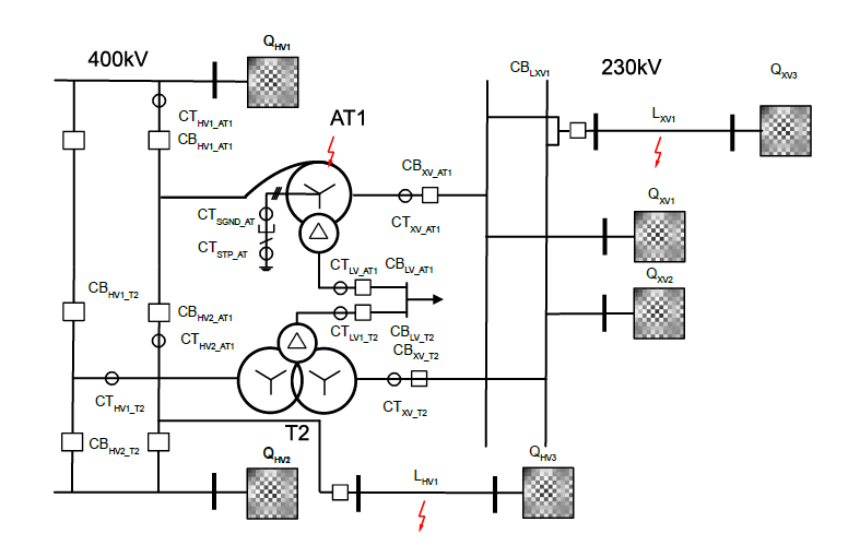
Figure 7 - Single-line diagram of the test RTDS power system
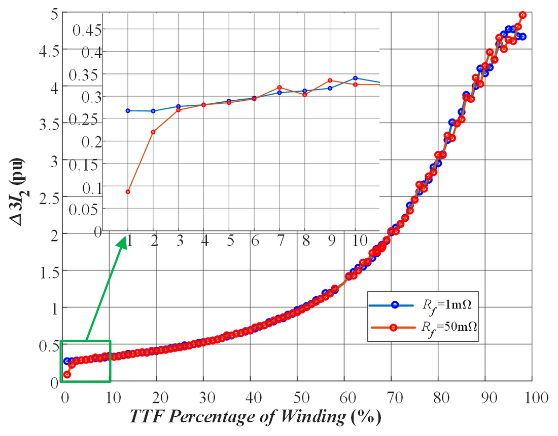
Figure 8 - Incremental negative-sequence current as a function of the percentage of short-circuited turns for TTFs in the series winding
3.2. Performance Evaluation regarding Dependability
The investigation of the presented protection scheme’s performance concerning dependability focuses on verifying the operating characteristic's safety margin during TTFs with the influencing variables direct current and harmonic components in the fault current. Additionally, the internal settings of the stabilisation criteria have been evaluated, and no blocking is activated in case of TTFs and simultaneous CT measurement errors, power grid unbalance and tap changer operation. The simulation parameter’s fault location, percentage faulted turns, fault resistance and fault inception angle of the TTFs have been varied. The pre-fault power system conditions as load flow, tap-changer position, time after transformer energisation, and external faults have been applied before the TTF. Figure 9 (a) shows the operating points for TTFs with 1 % short-circuited turns in the percentage restrained characteristics of the standard transformer differential protection (87T). As can be observed, the standard transformer differential protection is undependable for such types of TTFs. On the other hand, Figure 9 (b) shows the operating points for the same TTFs in the incremental negative-sequence differential current percentage characteristic (87QI). The proposed protection scheme is dependable for such types of TTFs.
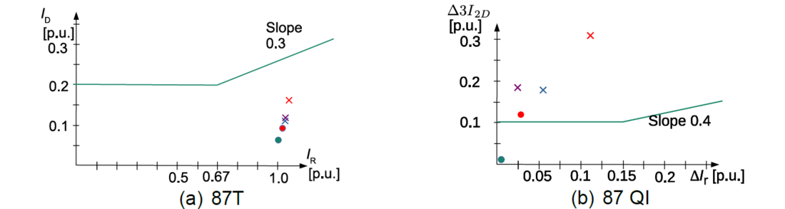
Figure 9 - Operating points in the (a) 87T and (b) 87QI percentage restraint characteristic for TTFs with
1% short-circuited turns
 Pre-fault
  common winding Rsc 50mΩ
  serial winding Rsc 1mΩ
  common winding Rsc 1mΩ
  delta winding Rsc 1mΩ
Figure 10 shows the TTF transient with the operating and restraint quantity and the indications of the proposed TTF protection scheme. As can be observed, the terminal current change is very low, but the sensitive 87 QI protection operates reliably after one cycle of the power system frequency after the TTF inception.
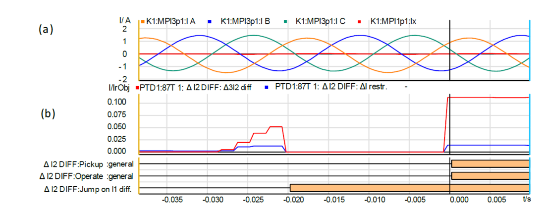
Figure 10 - sensitive 87QI TTF protection quantities and indications for a TTF in the common winding
for 1% of short-circuited turns and fault resistance 50mΩ
(a) terminal current HV (b) incremental negative-sequence differential and restraint quantity
Dependability for Evolving TTFs in the Presence of External Faults
Figure 11 shows a transient of an evolving TTF in the presence of an external fault with the operating and restraint quantities and the indications of the proposed TTF protection scheme. As can be observed in Figure 11 (b), after the external fault inception the incremental restraining quantity is very large and an incremental negative-sequence current of 0.45 p.u. is generated due to a tap-changer ratio mismatch of 10 per cent. The operating point in the incremental percentage restraint characteristic is far below the slope and provides high security for CT errors. After 9 milliseconds an evolving TTF with 1% short-circuited turns occurs. As can be seen in Figure 11 (b) and (c), an incremental negative-sequence current of 0.22 p.u. is determined and exceeds the incremental percentage restraint characteristic. It can be concluded that the proposed sensitive TTF protection schemes provide high dependability even if the TTF is evolving after an external fault.
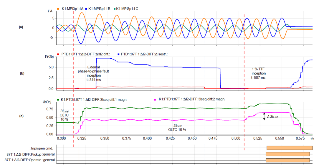
Figure 11 - sensitive 87QI TTF protection quantities and indications for an evolving TTF in the common winding in the presence of an external phase-to-phase fault for 1% of short-circuited turns and fault resistance 50mΩ with tap changer mismatch of 10 % (a) terminal current HV (b) incremental negative-sequence differential and restraint quantity (c) positive- and negative-sequence differential
3.3. Performance of the Incremental TTF Protection Scheme regarding Security
The validation of the security of the sensitive 87 QI TTF protection scheme with respect to adverse conditions such as external faults, transformer energisation, switching and load switching is an indispensable prerequisite for the deployment in the power grid. False differential currents are not measured only at high short-circuit currents in case of external faults, but also in the steady-state load range at switching loads with DC component in the current due to non-linear CT magnetising characteristic. Another source of differential currents is an increased transformer magnetising current due to overexcitation and inrush conditions. A slightly increased transformer magnetising current must also be taken into account for the very sensitive threshold. Increased magnetising currents in the power transformer occur not only at transformer energisation but as recovery inrush current, sympathetic inrush current or during inverter-based overfluxing. Both transformers in the test power system shown Figure 7 have non-linear magnetization characteristics. A non-linear CT model of non-gapped iron core CTs with remanence was used. The stability against the unwanted operation of the sensitive 87QI TTF protection has been ensured for all kinds of external faults at different network time constants up to 300 milliseconds and particularly for long fault-clearing times and auto-reclosure (AR) cycles with the second energisation of the CT. The CT dimensioning complies with standard IEC 61869-100 [17] and the CT requirements of the standard transformer differential protection relay [13]. The modelled non-gapped class 5P iron cores have a limiting operating accuracy factor (ALF') of 25 and were tested with a remanence of up to 80% .
The superior performance of the zero-sequence current stabilisation criterion to discriminate the false differential current from TTF is demonstrated using the transient of a phase-to-ground fault with unsuccessful AR shown in Figure 12. As can be seen, three cycles after fault inception, the CT saturates, and the incremental negative-sequence current exceeds the restraining characteristic so that the pickup indication is set. At the same time, the zero-sequence current ratio exceeds the internal threshold value of 0.1 p.u. with a value of approximately one p.u.. As a result, the Operate indication is blocked. In the second AR cycle, immediately after the circuit breaker is switched on, a false differential current is generated due to the CT remanence. Here too, the Operate indication is blocked by the zero-sequence current stabilisation criterion.
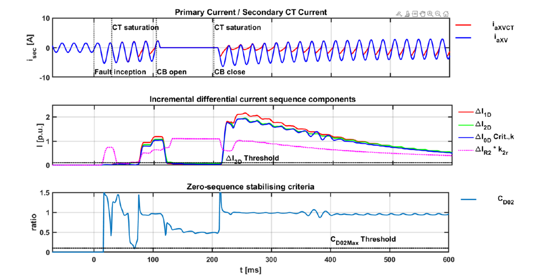
Figure 12 - 87QI sensitive TTF protection quantities and indications of an external phase-to-ground fault with unsuccessful AR and medium CT saturation (a) original phase current and CT secondary current (b) incremental positive and negative-sequence differential current (c) zero-sequence stabilisation criterion
4. Conclusion
The results of the RTDS tests with the implemented sensitive 87QI TTF protection are very promising in terms of dependability and security. The dependability for TTFs with a small number of short-circuited turns or with fault resistance is significantly higher than in the standard transformer differential protection even under load conditions and in the event of an evolving fault in the presence of an external fault.
The CWA method and the novel vectorial similarity criterion effectively discriminate TTFs from inrush or overexcitation conditions without the drawbacks of harmonic blocking. The transient tests confirmed that the same CT requirements apply as to the standard differential protection. The zero-sequence current differential stabilisation criterion ensures security in the case of false differential current due to non-linear CT behaviour during external faults.The implemented 87QI sensitive protection scheme requires no special adaption to different power transformer types and on-load tap changer operating range. Only the sensitivity threshold is assessable for the customer to adapt to lower CT requirements.
Of course, some limitations on dependability impose the absence of incremental quantities on switching on the transformer with a TTF (Switch-On-to-Fault Situation).
This is compensated by the advantages of the incremental quantities and the consideration of the sensitive turn-to-turn protection as an add-on function to the transformer differential protection restrained stage, similar to the fast unrestrained stage.
References
- C. de J. Ribeiro, A. P. Marques, C. H. B. Azevedo, D. C. P. Souza, B. P. Alvarenga, and R.G. Nogueira, “Faults and defects in power transformers - a case study,” in 2009 IEEE electrical insulation conference, May 2009, pp. 142–145. doi: 10.1109/EIC.2009.5166333.
- CIGRÉ WG A2.37, “Transformer Reliability Survey,” Paris, Brochure 642, 2015.
- A. Wiszniewski, K. Solak, W. Rebizant, and L. Schiel, “Calculation of the lowest currents caused by turn-to-turn short-circuits in power transformers,” Int. J. Electr. Power Energy Syst., vol. 95, pp. 301–306, 2018.
- Z. Gajic, I. Brnčić, B. Hillström, I. Ivankovic, S. Hep, and Croatia, “Sensitive turn-to-turn fault protection for power transformers,” Jan. 2005.
- F. Mieske, K. Solak, and W. Rebizant, “Dependability analysis of the negative-sequence turn-to-turn fault protection schemes for MMC-HVDC converter transformers,” Int. J. Electr. Power Energy Syst., vol. 160, p. 110129, Sep. 2024, doi: 10.1016/j.ijepes.2024.110129.
- N. Fischer and C. A. Labuschagne, “Negative sequence differential element,” US7903381B2
- I. SCHWEITZER ENGINEERING LABORATORIES, Current Differential and Voltage Protection SEL-487E-3, -4 Relay. 2017.
- B. Kasztenny, N. Fischer, and H. J. Altuve, “Negative-sequence differential protection - principles, sensitivity, and security,” in 2015 68th Annual Conference for Protective Relay Engineers, Mar. 2015, pp. 364–378. doi: 10.1109/CPRE.2015.7102180.
- ABB, Transformer protection RET670 relay Version 2.2 IEC Application Manual. 2017.
- K. Solak, F. Mieske, and S. Schneider, “Negative-Sequence Current Integral Method for Detection of Turn-to-Turn Faults Between Two Parallel Conductors in Power Transformers”.
- N. Farzin, M. Vakilian, and E. Hajipour, “Practical implementation of a new percentage-base turn-to-turn fault detection algorithm to transformer digital differential relay,” Int. J. Electr. Power Energy Syst., vol. 121, p. 106158, Oct. 2020, doi: 10.1016/j.ijepes.2020.106158.
- N. Farzin, M. Vakilian, and E. Hajipour, “Transformer turn-to-turn fault protection based on fault-related incremental currents,” IEEE Trans. Power Deliv., vol. 34, no. 2, pp. 700-709, Apr. 2019, doi: 10.1109/TPWRD.2019.2893279.
- RTDS Technologies Inc., RSCAD Power System Components Manual. 150 Innovation Drive Winnipeg, MB R3T 2E1 CANADA, 2022.
- “Development of the Coil Volume Method for Time-Domain Simulation of Internal Faults in Transformers.” Michigan Technological University ProQuest Dissertations Publishing, 2019.[Online].
- "EMTP-ATP Manuals," EEUG, 2001.