Accuracy testing of an inductive voltage transformer under rated fundamental voltage and superimposed harmonics
Authors
Y. LI, W. YAN - National Measurement Institute, Australia
I. RANMANNA DEWAYALAGE - University of Wollongong, Australia

Summary
Measurement of harmonics in high-voltage networks has become increasingly important due to the increasing presence of harmonic voltages produced by power electronics in renewable energy generation plants. While new types of wideband voltage measurement devices are being deployed, the majority of voltage measurement instruments in the present high-voltage networks are still either the traditional inductive voltage transformers (IVTs) or the capacitive voltage transformers (CVTs). The traditional voltage transformers are designed for measuring at the power frequency and accuracy tests on these transformers are only performed at the fundamental frequency in accordance with international standards. It has been shown that frequencies of the harmonics from the renewable power plants can be as high tens of kilohertz at some system voltage levels. This poses challenges for measuring the harmonics utilising the majority of voltage transformers in the networks if the accuracy of these transforms for measuring harmonics has not been determined. Therefore, determination of the accuracy of the transformers for harmonic voltages with traceable measurements becomes critical.
While the bandwidth of the high-voltage CVTs have been found to be insufficient for accurately measuring harmonics beyond a few hundred hertz, some IVTs, however, are believed to be potentially capable of accurately measuring harmonics of much higher frequencies.
In this paper, the ratio accuracy and the phase displacement of a 33 kV IVT used in a gas insulated substation were measured under harmonic voltages up to 50th order, i.e. 2500 Hz. Since the accuracy of an IVT is usually significantly dependent of the applied voltage, tests were performed not only with the harmonic voltages, which are normally significantly lower than the rated fundamental voltage, but also with harmonic voltages superimposed on the rated fundamental voltage. Accuracy results obtained with different levels of harmonic voltages under different test conditions are presented. The test results showed that maximum ratio error and maximum phase displacement of this particular IVT were +4.5% and -1.2 crad respectively, under the rated fundamental voltage superimposed with harmonics of up to 2500 Hz, and did not differ significantly from those measured with the individual harmonic voltages alone.
The paper also describes the measurement system used for performing the accuracy tests, which included a high-voltage capacitive divider, two precision digitisers and measurement software that allows synchronisation of the two digitisers. The measurement uncertainties are also discussed.
Keywords
Voltage transformer, accuracy test, harmonic measurement1. Introduction
The measurement of harmonic voltages is essential to ensure conformity with standards that regulate the operation of the power system [1,2]. In medium-voltage and high-voltage substations, voltage transformers are usually used to step down the voltages to levels that can be measured by power quality meters covering the frequencies of interest. In order to evaluate the overall accuracy of harmonic measurements, accuracy of these voltage transformers should be determined not only at the fundamental power frequency, but also at harmonic frequencies of interests. Current international and Australian standards [3] on instrument voltage transformers, however, only require accuracy test at the fundamental power frequency. Determination of the accuracies of these voltage transformers over a wide range of frequencies is essential for them to be used for harmonic measurements in the high-voltage network. Some of these voltage transformers, particularly the pure inductive types, may offer higher accuracies than most of the measurement methods currently used for harmonic measurements, such as using high frequency current transformers to measure currents at various locations of the substation to deduce the voltage signals. However, several researchers have shown that the frequency response characterization of inductive voltage transformers performed at low voltage levels may not accurately represent their voltage ratio and phase errors at the presence of HV fundamental component and distorted waveform conditions [4-7].
This paper presents and discusses the experience of accuracy testing of a voltage transformer of the inductive type for its performance under composite voltages and individual harmonic voltages, with adequate control of metrological traceability of the measurements. In particular, the reference system used in the measurement, including the high-voltage divider, the digitisers for measuring the outputs of the high-voltage divider and the transformer and the software for synchronising the digitisers are described. The major measurement uncertainty components are discussed, which illustrates the factors that limit accuracy that can be achieved in this particular measurement.
General comments on the selection of the methods for testing the accuracy of inductive voltage transformers for harmonic measurements are also made based on the test results.
2. The voltage transformer under test
The voltage transformer tested in the paper was to be used as a metering and protection transformer in a new substation. Its accuracy at the power frequency of 50 Hz has been tested to meet requirements for a class 0.2 transformer. The accuracy of the voltage transformer was measured in the tests described in this paper at frequencies up to 2500 Hz to assess if it was also suitable for measuring harmonic voltages.
Relevant technical parameters of the transformer are given in Table 1.
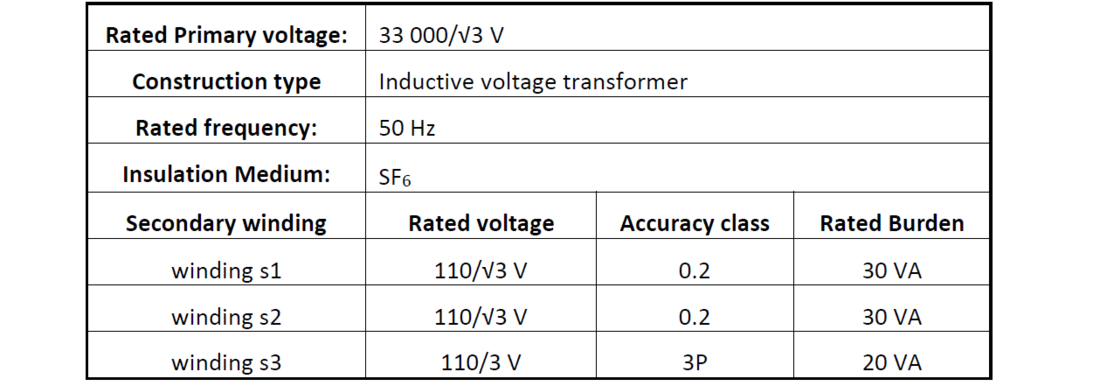
Table 1 - Relevant parameters of the voltage transformer under test
3. The measurement system
Since most voltage transformer testing sets operate only at one power frequency, they cannot be used in testing with a voltage at its frequency significantly higher that the power frequency or with a composite voltage with more than one frequencies. A measurement system [8] based on two digitisers was therefore built to perform the measurements, by measuring the input voltage across the primary winding and output voltage across the secondary winding under test, simultaneously using the two digitisers. The digitised signals were then used to determine the voltage ratio and phase displacement of the voltage transformer under test.
A high-voltage capacitive divider was also used for measuring the input voltage at the primary winding of the transformer under test. The high-voltage capacitive divider consisted of a three-terminal pressurised gas capacitor as the high-voltage arm and a multi-layer ceramic capacitor as the low-voltage arm. The voltage ratio and the phase displacement of the capacitive divider were calibrated at 1 kV against a reference system consisting of a precision resistive divider and a buffer amplifier, with expanded uncertainties (k=2) of 0.07% for ratio and 0.09 crad for phase error. The measured values are shown in Figure 1. The voltage linearity of the divider ratio was verified as negligible at voltages up to the rated primary voltage of the transformer under test.

Figure 1 - Measured voltage ratio and phase error of the reference capacitive divider
The input voltage at the primary winding of the transformer was measured with the high-voltage capacitive divider, with the divider output voltage measured with one of the digitisers. The output voltage at the transformer secondary winding under test was measured with the other digitiser.
The digitising functions of two precision DMMs (digital multi-meters) of the same model were used in the measurement. A sample rate of 50 kS/s and a resolution of 18 bits were used for the measurements. The measurement software was capable of synchronising the measurements of the two digitisers and calculating the voltage amplitude and phase of each frequency component in the recorded voltage waveforms using a FFT (Fast Fourier Transform) algorithm. The uncertainty contribution of each of the digitisers to the ratio error measurements was estimated as 0.04% of the measured voltage ratio for measuring the 1% harmonic voltage superimposed on the rated fundamental voltage. This digitiser uncertainty contribution was estimated as 0.01% of the measured voltage ratio when the harmonic voltage was applied alone.
The software contribution to the uncertainty of the ratio error measurement was estimated as 0.02% of the harmonic voltage, which mainly came from the FFT algorithm.
Although the two DMMs are of the same model, the time delays from receiving the same measurement trigger signal to the start of the measurements (sampling) were significantly different in comparison with the uncertainty required for the phase displacement measurements. Therefore, the time delays between the two digitisers were measured with the same voltage signals simultaneously applied to the two digitisers. The time delays for all frequencies were measured and then used to correct the measured phase displacement values. A standard uncertainty (type A) value of 0.65 μs was used as a component of the uncertainty for the measured time delays. This standard uncertainty value was obtained from the maximum standard deviation value of the repeated time delay measurements at all frequencies. This time delay uncertainty value of 0.65 μs equates to 0.01 crad at 50 Hz and 0.51 crad at 2500 Hz respectively. Since a single value of the expanded uncertainty was given for phase displacements at all frequencies, the value of 0.51 crad was used for the time delay component, which became the dominant component for the phase displacement uncertainty.
Schematics of the measurement setups are shown in Figure 2.
The circuit on the left was used to generate and measure the composite voltages. The step-up transformer was used to generate the high voltage at the fundamental frequency of 50 Hz. A function generator and a power amplifier were used to generate the low voltage at a harmonic frequency. The harmonic voltage was fed into the low voltage terminal of the step-up transformer so that the harmonic voltage was superimposed on the high-voltage with the fundamental frequency. A trigger circuit was used to trigger the function generator to align the phase of the harmonic voltage with that of the fundamental voltage.
The circuit on the right was used to generate and measure the harmonic voltages.
In both cases, the digitisers of the two DMMs were used to measure the respective output voltages of the reference divider and the transformer under test.

Figure 2 - Schematics of the measurement setups
left: Measurement with composite voltage, right: measurement with low voltage at a single frequency
4. Test results
The accuracy of the voltage transformer at harmonic frequencies was measured under two different conditions. First, the transformer was tested for its voltage ratio error and phase displacement under sinusoidal low voltage waveforms. Secondly, the transformer was tested under a high voltage composite test voltage consisting of a 33/√3 kV fundamental frequency component and a single harmonic component. The frequency of the harmonic component was varied from 100 Hz to 2500 Hz in 50 Hz frequency steps in each of the tests. For each harmonic order (h), the voltage ratio error (Ɛℎ) and phase displacement (Δ?ℎ) were evaluated according to (1) and (2) respectively.
(1)
(2)
where, ?? and ?ℎ are the rated voltage ratio and the measured ratio at harmonic order (h) respectively, ??ℎ and ??ℎ are applied primary harmonic voltage and measured secondary harmonic voltage respectively. and
are the measured secondary and the primary phase angles at the harmonic frequency respectively.
A summary of the test conditions and test results is given in Table 2. The winding tested was “s2”, which was proposed to be used for measuring the harmonic voltages when installed in the substation. The burdens applied to the three secondary windings are also given in Table 2. The maximum error of voltage ratio and maximum phase displacement were always found at 2500 Hz, the highest harmonic frequency tested, for all test conditions.
The change of ratio error and change of phase displacement with harmonic frequency of some tests are given in Figures 3 to 6.
The ratio errors and phase displacements measured at 50 Hz were given in Table 2.
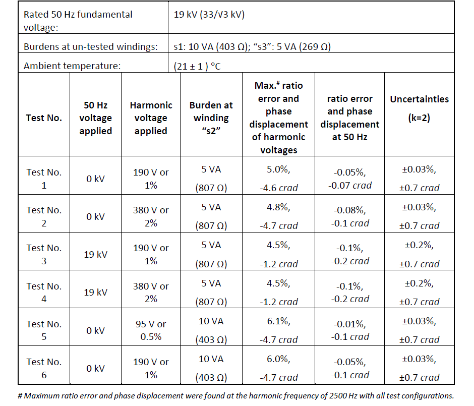
Table 2 - A summary of tests performed and test results

Figure 3 - Measured ratio error in Test No. 1 and Test No.2
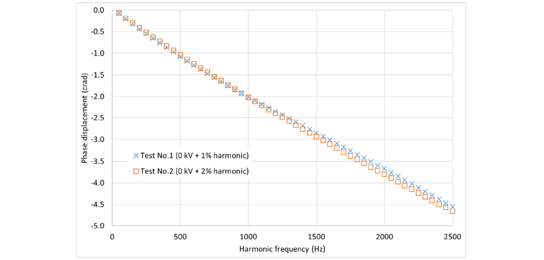
Figure 4 - Measured phase displacement in Test No. 1 and Test No.2
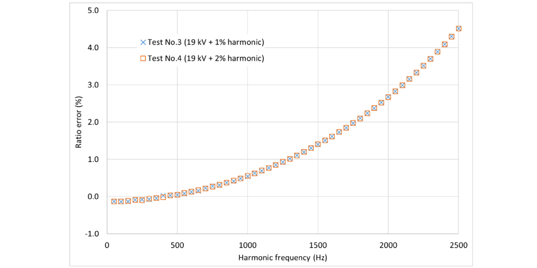
Figure 5 - Measured ratio error in Test No. 3 and Test No.4

Figure 6 - Measured phase displacement in Test No. 3 and Test No.4
5. Discussion
This discussion section mainly aims to gain some insights into the behaviour of inductive voltage transformers under different test voltages, so that an efficient test method may be found for testing their accuracy for measuring the harmonic voltages in the network.
The maximum ratio errors measured with low voltages of individual frequencies (Tests No.1 and No.2) appeared to be higher than those measured with composite voltages (Tests No.3 and No.4). In Tests No.5 and No.6, the burden was increased to 10 VA and the ratio errors were increased to about 6%, which were higher than those in Test No.1 and No.2, where the burden was 5 VA. However, these differences are insignificant if measured in harmonic voltage amplitude relative to the rated primary voltage. For example, if the harmonic voltage is 2% of the rated voltage, the measured harmonic voltage relative to the rated voltage will be 2.10% with a ratio error of 5% and 2.09% with a ratio error of 4.5%. So in the case of this particular transformer tested, whether the low voltage results or the composite high-voltage results are used would not have a practical impact on most applications, such as monitoring the limit of harmonic voltages in the network.
The 50 Hz results in Table 2 show that the errors also changed only very slightly when applied primary voltage was changed from harmonic low voltages to composite high voltages in this particular case.
It should also be noted that error magnitudes were sufficiently low, and applying corrections for the measured errors would not be justifiable in most applications. The measured maximum ratio error at 2500 Hz was 5% while at 1500 Hz it was only 2%. Errors at these levels would have negligible impact on the operational decisions based on the measured harmonic voltage levels.
It is expected that most inductive voltage transformers in an electricity network would have a similar behaviour to the one reported in this paper. Transformers with higher rated voltages may have higher errors at harmonic frequencies, but the trends would be similar to those reported in this paper. A careful study of results reported in [4-7] shows similar trends and behaviours. Based on the results of this and others, some general comments can be summarised as follows:
- It would be generally not necessary to use the composite voltage, i.e., the voltage consists of the rated fundamental voltage with superimposed harmonic voltage, to test the errors of the inductive transformers at harmonic frequencies.
- The errors of this type of transformers at harmonic frequencies should be measured with single frequency voltages at a level as high as practical, with the main limiting factor being the available power and voltage in the high frequency power supply. Initial assessments can be made at several voltage levels in the range below 1 kV.
For future work, tests on more inductive transformers with both composite voltages and harmonic voltages alone can be performed to verify the validity of the above comments. Such work would be helpful to verify if testing the accuracy of the inductive voltage transformers with low level harmonic voltages alone is sufficient for common network measurement applications.
The measurements reported in this paper were performed using digitisers among the most accurate available in this frequency range. The software used was also of a high accuracy, which had been verified by using it to measure voltages that are traceable to the Australian national standard of the volt. However, this paper reports conservatively high overall uncertainties, to avoid quoting uncertainty values for individual frequencies. It is believed that measurement systems using commercial devices, such as high-voltage capacitive dividers, and software would be capable of achieving uncertainties not significantly higher than those reported in this paper. The main uncertainty contributions would be from measuring the ratio and the phase error of the high-voltage divider at the harmonic frequencies.
6. Conclusion
- The measured error of voltage ratio and phase displacement of the harmonic voltages increased with frequency, under the test condition of composite high-voltages and harmonic low voltage.
- The effect of voltage level of the harmonic test voltage applied alone was appreciable, but would be negligible for the purpose of monitoring the levels of harmonic voltages.
- The effect of burden change was appreciable, but also negligible for monitoring purposes.
- With the 5 VA burden, the maximum differences in the ratio error and the phase displacement between the test with composite high voltage and the test with harmonic low voltage were 0.5% and 3.5 crad, respectively. These low levels of differences indicate that testing using low voltages of individual frequencies would yield virtually the same results as using the composite voltage for the purposes of monitoring the network harmonic voltage levels.
References
- IEEE Recommended Practice and Requirements for Harmonic Control in Electric Power Systems IEEE-519, IEEE, 3 Park Avenue,New York, NY 10016-5997 USA 2014.
- BS EN 50160 Voltage characteristics of electricity supplied by public electricity networks, BS-EN-50160, 2010.
- IEC 61869-3:2011 (AS/NZS 61869:3) Instrument transformers - Part 3: Additonal requirements for inductive voltge transformers.
- T. Lei et al., "Behavior of voltage transformers under distorted conditions," in 2016 IEEE International Instrumentation and Measurement Technology Conference Proceedings, 23-26 May 2016 2016, pp. 1-6, doi: 10.1109/I2MTC.2016.7520344.
- M. Kaczmarek and E. Stano, "Measuring system for testing the transformation accuracy of harmonics of distorted voltage by medium voltage instrument transformers," Measurement, vol. 181, p. 109628, 2021/08/01/ 2021, doi: https://doi.org/10.1016/j.measurement.2021.109628.
- G. Crotti, D. Gallo, D. Giordano, C. Landi, M. Luiso, and M. Modarres, "Frequency Response of MV Voltage Transformer Under Actual Waveforms," IEEE Transactions on Instrumentation and Measurement, vol. 66, no. 6, pp. 1146-1154, 2017, doi: 10.1109/TIM.2017.2652638.
- D. Filipović-Grčić, B. Filipović-Grčić, and D. Krajtner, "Frequency response and harmonic distortion testing of inductive voltage transformer used for power quality measurements," Procedia Engineering, vol. 202, pp. 159-167, 2017/01/01/ 2017, doi: https://doi.org/10.1016/j.proeng.2017.09.703.
- J. Imanka et al., "Calibration System for High Voltage Transformers with Multi-tone Signals at Frequencies up to 10 kHz,” Conference on Precision Electromagnetic Measurements. Conference Digest. CPEM 2022, New Zealand, 2022.