Wind Power Integration in Weak Grids
Authors
J. SIVASANKARAN, M. CAMPOS, R. KABIRI - Vestas Wind Systems A/S

Summary
Managing power delivery from windfarms is becoming more challenging as system strength is decreasing, since the stability issues causes unreliable performance and reduces the renewable energy penetration. Advanced control approaches can be developed to enhance the wind turbine performance to increase the stability margins, and thus help connecting more distributed generation into weak grids where the renewable resources are located. This paper addresses some of the key weak grid connection challenges which are affecting the performance of inverter-based resources. Furthermore, this paper presents a control scheme using dynamic voltage control at wind turbine generator terminals and optimizing the reactive current injection rate to help overcome these challenges. Simulation results are provided to verify the mitigation influence of these control strategies on weak grid operation.
Keywords
Wind Turbine Generator Control, Weak Grid, Voltage Control, Wind Power, Interconnection Challenges1. Introduction
The need for a sustainable and cost-effective energy transition to support global climate control has driven aggressive green energy policies across the globe. Subsequently electrical grid landscape in the last two decades has evolved at a rapid pace. New technological development and maximizing the effectiveness of existing technology is of paramount focus for generators and network operators. The success and effective deployment of the grid following inverter-based resources (IBRs) in the recent past is being challenged by the rate of displacement of the traditional synchronous generation, balance of plant design complexities and technological development towards capturing energy sources further away from the load centres [1].
The operation of wind power plants in weak grids [2] is increasingly challenging as the available short circuit levels are decreasing progressively and raises concerns around stable and reliable grid operation due to control interactions between inverter-based generators and rest of the grid [3]. As the strength of grid connection reduces progressively, extending existing technology to connect and remain in stable operation without additional hardware is seen as the most cost-effective approach compared to other solutions.
This paper investigates some of the technical challenges concerning weak grid connections, from an original equipment manufacturer (OEM) perspective. It places special highlight on the following:
- Response to voltage disturbance is a key challenge for windfarms in a weak grid application. The generating units should have a fast and resilient local response to reject disturbances during steady state grid operation. At the same time, generating unit level response towards voltage disturbances shouldn’t intervene with the compliance objective set out at the park level. Hence it is essential to combine and coordinate it with PPC’s control action. At a higher level both the control loops need to synergise well to ensure compliance with network standards at the point of connection [4]-[5].
- Dynamic performance of wind turbines connected to nodes operating at low system strength, during under voltage events along with its impact on current control schemes and converter tuning. Solutions in the form of stabilization of response through introduction of reactive controller lag during transients for improved FRT and fault recovery performance [6]-[7]. Such efforts explore opportunities to further expand existing grid following technology to provide better dynamic voltage support.
2. Weak Grid Connection Challenges
From a grid following IBR’s perspective, challenges towards connecting to a power system with a low short circuit ratio can be categorised as following:
- Network characteristics and associated sensitivity of voltage to changes in reactive power.
- Compatibility of plant controller tuning with dynamic changes in network characteristics/gain.
- Limitation with penetration level of distributed generation in weak grids.
- Rate of response along the quadrature axis of the line current to support voltage disturbances during steady state and transients.
2.1. Inherent Weak Grid Characteristics
Network characteristics (in the absence of node voltage controllers) governs the sensitivity of the voltage magnitude at a given node corresponding to changes in active and reactive power. The geographical distribution of grid following inverters increases the local node (wind turbine generator (WTG) terminal) voltage sensitivity compared to the remote connection point (point of common coupling (PCC)) as shown in Figure 1, where the voltage control characteristics are typically defined and configured. This difference is further exacerbated with reduction in fault level and increase in magnitude of reactive power change as shown in Figure 1 (a). In the absence of local node voltage correction and delayed corrective action from plant controller, step change in reactive power setpoint to the WTGs results in oscillatory voltage response (Figure 1 (b)). Plots in Figure 1 are derived from an EMT assessment involving step changes in reactive power setpoint at park level and WTG level.
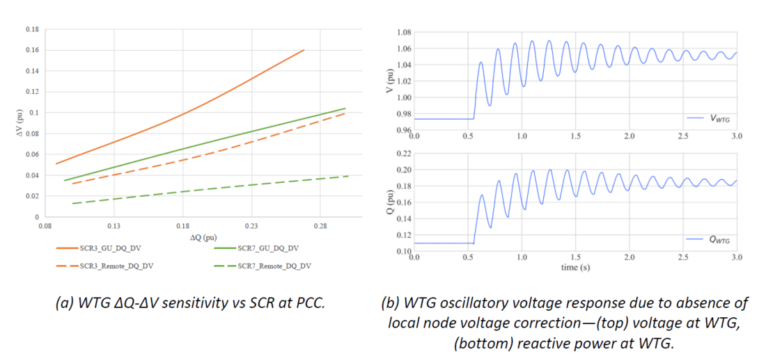
Figure 1 - Sensitivity of WTG voltage to grid characteristics
2.2. Variation in Network characteristics
Dynamic changes in the network characteristic occurs throughout the operation of power system. The nature of the changes varies on a continuous basis ranging from a minor deviation during planned/controlled steady state operation to a major change due to a fault resulting in a step change in system strength. These network changes are perceived as variations in network gain within the power plant control system. Robustness of the PPC tuning, and the nature of the network change would determine the margin of stability of the overall voltage control operation.
PPC is configured to control voltage at a specific network bus utilizing electrically distributed reactive power reserves. Control system parameterisation of PPC is performed with an objective of providing adequate stability margin for a wide range of network changes (usually tuned for the range of sitespecific minimum to maximum fault levels). However, following factors independently or in combination could shift the system to an unstable operating range:
- Mismatch in network gain and control system parameterisation.
- Inadequate controller sampling rate.
- Geographical distribution of secondary controllers and associated delay in communication.
Figure 2 illustrates an unstable voltage control operation preceded by a network event. The post-fault system characteristics has changed due to the isolation of a part of the network following a contingency and system strength has reduced considerably compared to the pre-fault condition.
2.3. Weak Grid and Limitation on Renewable Penetration
The extent of renewable penetration within a segment of the power system is determined by many factors which includes system side constrains and generators side limitations. Given that the system side constraints take longer and expensive augmentation due to the impact on multiple stakeholders, on most occasions the rating of the generator is highly influenced by the technology of IBR and park level augmentation. To an extent the operational short circuit ratio (SCR) range can be lowered by additional augmentation at park level. However, this approach is challenged beyond certain level due to techno-commercial constrains. Figure 3 shows results from a planning feasibility study to connect a 410MW windfarm to a weak grid, with additional dynamic reactive plant. To mitigate unstable operation after the contingency and to facilitate renewable generation at 410MW the increase in reactive plant is substantial and commercially not viable.
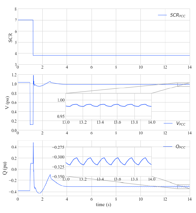
Figure 2 - Impact of variation in network characteristics—(top) SCR at PCC, (middle) voltage at PCC, (bottom) reactive power at PCC
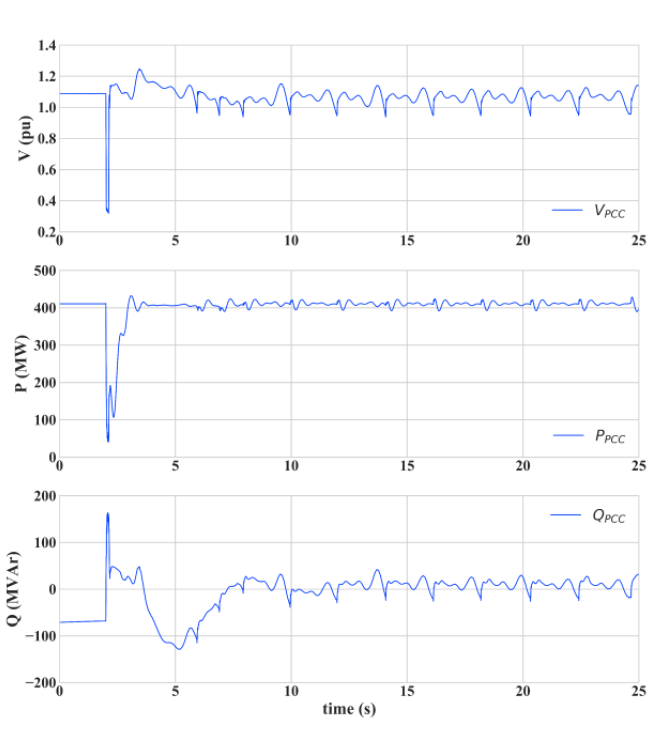
Figure 3 - limitation on penetration in weak grids—(top) voltage at PCC, (middle) active power at PCC, (bottom) reactive power at PCC
2.4. Rate of Reactive Current Response
Grid supportive response at an optimal rate during steady state voltage disturbance and the ability of the WTG to respond with appropriate reactive power injection for certain critical mode of oscillation is crucial for stable operation in a weak grid connection. Factors such as lack of local node voltage correction coupled with delays/bandwidth limitations associated with primary controllers has limited the seamless connection of windfarms to low SCR connections without additional plant level augmentation. During transient voltage support, the rate at which a precalculated reactive current magnitude is injected into the grid could result in instability due to the lack of insufficient stability margin. This appears as undamped oscillations in response as shown in Figure 4.
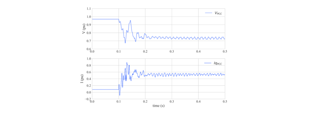
Figure 4 - Insufficient stability margin—(top) voltage at PCC, (bottom) reactive current at PCC
3. Technical Solutions
3.1. WTG Dynamic Voltage Control (DVC) and Weak Grid Operation
The challenge posed by increased voltage sensitivity in weak network connections due to reactive power changes can be manage through an immediate disturbance rejection response mechanism [4]. For a counter acting response to be effective it would have to be closer to the reactive power source at the WTG level whilst fulfilling plant level voltage control objective. A dynamic WTG level voltage support scheme described briefly in this section, widens the operational SCR range allowing turbines to be connected to weak networks.
The improvements at WTG level controls to enhance steady state performance in weak grid connection includes:
- adjusting plant controller Qset_WTG(PPC) with a reactive power setpoint (QDVC) derived at unit level based on the product of adjustable gain and magnitude of terminal voltage deviation from its filter steady state value (Qset_WTG = Qset_WTG(PPC) + QDVC),
- QDVC provides an immediate reaction to local voltage disturbance and can be controlled by an adjustable gain and reference limiters.
- adjustable filter cut-off frequencies to match connection requirements to obtain an overall stable performance.
The implementation of the above-mentioned control approach is shown in Figure 5. By setting the dynamic voltage control setpoint (QDVC) as a function of the local voltage measured, the WTG ensures operation in a wide range of conditions, as opposed to being limited to a specific setpoint.
A step change in reactive power setpoint to the WTG’s controller (operating in power control mode) would result in a corresponding change in its terminal voltage. The transition from the initial steady state to its final value is only controlled by network characteristics. Initial terminal voltage 1 in Figure 6(a), increases along the network characteristics towards the final steady state voltage 3 and the transition is oscillatory in the absence of local voltage correction.
Figure 6 (b), shows the impact of improved disturbance rejection and smooth transition due to the inclusion of a counteracting component derived from the measured local voltage. Transition from initial steady state is controlled at every step by the DVC until the final steady state voltage 3 is reached. The value of QDVC becomes zero at this point as its reference (filtered measured voltage) becomes equal to the measured final steady state voltage.
For a smaller step change in generating unit’s Qset_WTG(PPC) compared to its reactive power capability, the local voltage correction will not impact overall response characteristics such as rise time and settling time significantly. However, for a larger Qset_WTG(PPC) steps the DVC’s response will increase overall reactive power rise and settling time due to the nature of the parameterization of the voltage reference LPF and PPC setpoint saturation. Figure 7 compares the response during a smaller and larger generating unit’s Qset_WTG(PPC) change.
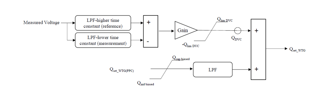
Figure 5 - Simplified block diagram of the WTG dynamic voltage control

Figure 6 - Step change in reactive power during steady state operation and corresponding voltage disturbance
rejection
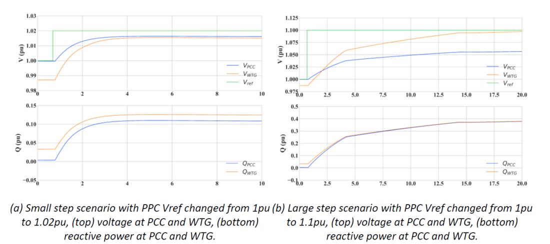
Figure 7 - Generating system response to step change in controller reference with DVC enabled
To improve the overall rise and settling time of the response, reactive power capability feedbacks from the generating unit are augmented beyond the actual capabilities before sending it to the PPC. These signals are expressed as Qcap biased and Qind biased in the implementation block diagram (Figure 5). The augmentation can be configured through user specified parameterization.
Inclusion of biased feedback limits saturates PPC Qset_WTG(PPC) to a higher value resulting in a faster dynamic response. Figure 8 shows the dynamic response with activation of PPC biased limit for large reference step. Please note that the WTG Qproduction is always limited to the actual generating units reactive power capabilities (Qcap and Qind). Comparing the results in Figure 7 (b) with the results in Figure 8, illustrates the improvement of the dynamic response with the introduction of the biased limits.
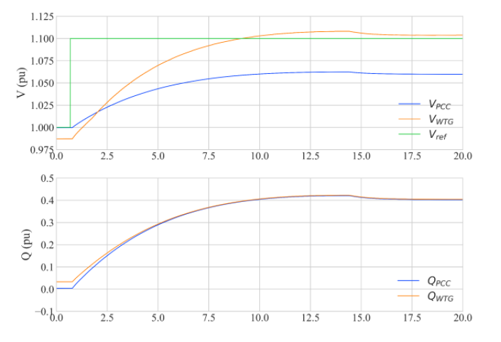
Figure 8 - Vref Step Change response in PPC Vslope Control Mode, DVC enabled and PPC receiving biased/normal WTG Qcap/ Qind limits, (top) voltage at PCC and WTG, (bottom) reactive power at PCC and WTG.
3.2. DVC and Network Characteristics Variation
Another major advantage of DVC at generating unit is the improved disturbance rejection capability for a wide range of network characteristics changes. A fixed park level voltage control system has its limits in the event of a network related changes as indicated in Figure 2. The contingency analysis indicated in Figure 2 is repeated with the local voltage correction enabled and the results show significant improvement in the post fault voltage control response as shown in Figure 9.
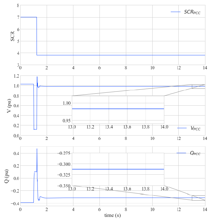
Figure 9 - Impact of variation in network characteristics with disturbance rejection—(top) SCR at PCC, (middle) voltage at PCC, (bottom) reactive power at PCC
3.3. DVC and Maximizing Renewable Penetration
To facilitate higher renewable penetration with regard to generator side constrains, the optimal approach is to maximise the existing IBR technology. As the associated cost increase is marginal the commercial burden in developing a higher rated generating system would be alleviated. The planning assessment highlighted in section 2.3, is repeated with WTGs configured to operate with DVC. Issues associated with post fault unstable operation have been mitigated as shown in Figure 10. Further an additional 120MW generator could be added to the generation without additional augmentation in reactive plant, refer Figure 11.
3.4. Rate of reactive current Response Optimisation
Immediate reaction offered by the DVC is grid supportive in connections where transient response rate is critical (for instance, response to certain critical mode of oscillation and steady state grid voltage change). Figure 12 shows the response at the park level for a step change in grid voltage. The rate of response has significantly improved with the local voltage correction. Typical response without DVC would include a slow reaction time due to plant controller sampling limitations and communication delays which would negatively impact voltage control response, especially from a generating system with a higher reactive power losses associated with balance of plant.
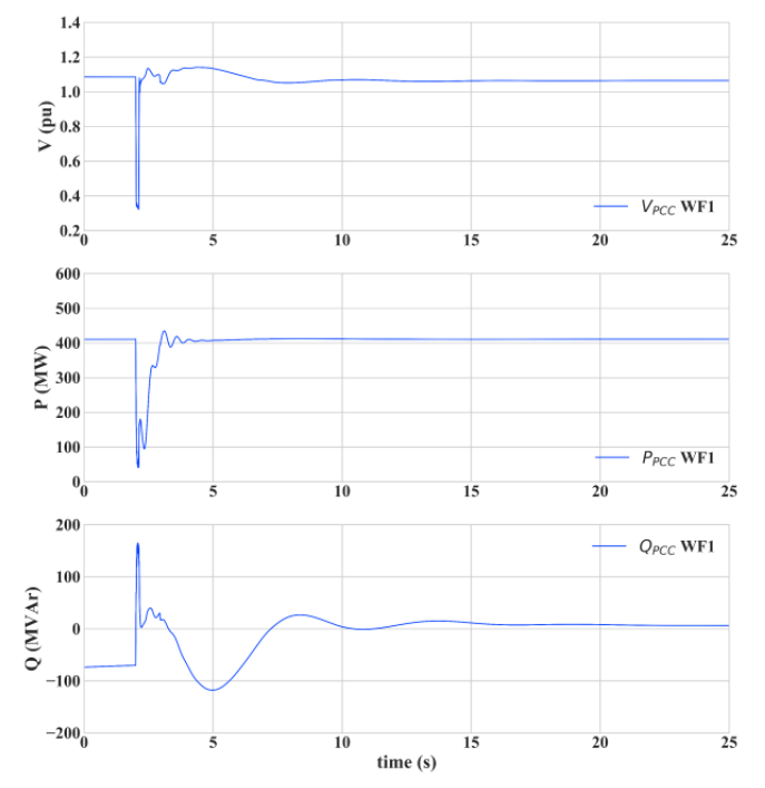
Figure 10 - Increase in penetration in weak grids (410 MW WF)—(top) voltage at PCC, (middle) active power at PCC, (bottom) reactive power at PCC
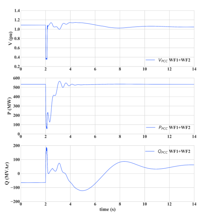
Figure 11 - Increase in penetration in weak grids (410 + 120 MW WF)—(top) voltage at PCC, (middle) active power at PCC, (bottom) reactive power at PCC
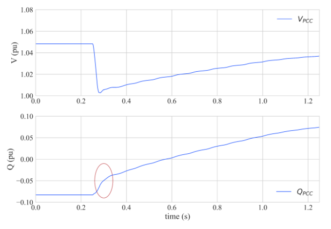
Figure 12 - Disturbance rejection during steady state grid voltage change, (top) voltage at PCC, (bottom) reactive power at PCC
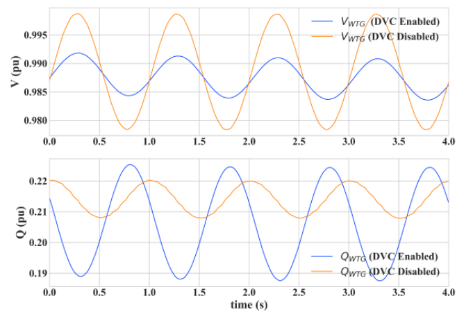
Figure 13 - Response to grid voltage oscillation, (top) voltage at WTG, (bottom) reactive power at WTG
Dynamic reaction from the generating system could be leveraged to provide a positive grid supportive response to certain critical mode of oscillations in grid voltage. Response in reactive power is opposing the change in voltage resulting in a peak-peak reduction (subject to system strength and the mode of oscillation) as shown in Figure 13.
Generating units are typically configured to inject reactive current at comparatively lower magnitude when connected to a grid with low system strength for stable fault ride through performance. One of the challenges in increasing the injection magnitude is the risk of response with high frequency noise and reduced stability margin. To improve the performance during fault ride through and reduce high frequency noise, a lag controller is introduced within the control system, refer to Figure 14.
The lag controller smoothens reactive current injection and helps avoid undesired oscillations. The overall control system response is significantly improved when compared to its response before the inclusion of the lag controller as shown in Figure 15. The response upon enabling the lag controller is without the high frequency noise and is expected to be slower comparatively. But considering the overall stable reactive current injection, slower reactive current rise time should be acceptable as part
of weak grid FRT performance.
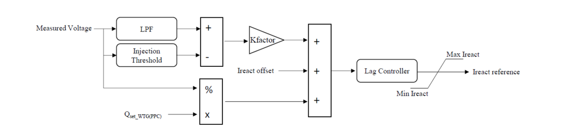
Figure 14 - Simplified block diagram of lag controller
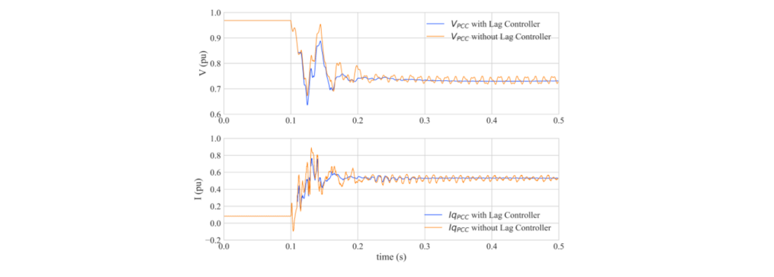
Figure 15 - Reactive current injection with and without lag compensator, (top) voltage at PCC, (bottom) reactive current at PCC
4. Conclusions
This paper explores some of the current challenges faced by wind turbine OEMs when attempting to interconnect power plants to weak power system nodes, identifying stability issues which impact the performance and consequently, limit the renewable energy penetration in networks with low system strength. A technical solution is then presented that utilises the WTG control to provide dynamic voltage control to deal with weak grid connections and changes in network characteristic. Furthermore, it is shown that the adapted design solution allows for more distributed generation to get connected in weak grids. In addition, a lag controller for reactive current injection is presented to enhance the WTG performance by avoiding undesired oscillations. Both of these solutions have proven to expand the wind power plant operation stability margin without the need for additional equipment at plant level. To confirm the concept, advanced analysis and simulation results has been included in the paper to confirm the strategy and its effectiveness.
References
- Integrating Inverter-Based Resources Into Low Short Circuit Strength Systems, Atlanta, GA, USA:NERC, Dec. 2017, [online]
- Connection of Wind Farms to Weak AC Networks, CIGRÉ, 2016, 2858733740, 9782858733743.
- Y. Zhou, D. D. Nguyen, P. C. Kjær and S. Saylors, "Connecting wind power plant with weak grid - Challenges and solutions," 2013 IEEE Power & Energy Society General Meeting, Vancouver, BC, Canada, 2013, pp. 1-7, doi: 10.1109/PESMG.2013.6672755
- T. Lund, H. Wu, H. Soltani, J. G. Nielsen, G. K. Andersen and X. Wang, "Operating Wind Power Plants Under Weak Grid Conditions Considering Voltage Stability Constraints," in IEEE Transactions on Power Electronics, vol. 37, no. 12, pp. 15482-15492, Dec. 2022, doi: 10.1109/TPEL.2022.3197308.
- Qinglai Guo, Hongbin Sun, Bin Wang, Boming Zhang, Wenchuan Wu, Lei Tang, “Hierarchical automatic voltage control for integration of large-scale wind power: Design and implementation,” in Electric Power Systems Research, vol 120, pp. 234-241, 2015, doi.org/10.1016/j.epsr.2014.02.012.
- T. Neumann, T. Wijnhoven, G. Deconinck and I. Erlich, "Enhanced Dynamic Voltage Control of Type 4 Wind Turbines During Unbalanced Grid Faults," in IEEE Transactions on Energy Conversion, vol. 30, no. 4, pp. 1650-1659, Dec. 2015, doi: 10.1109/TEC.2015.2470126.
- Göksu, Ö., Teodorescu, R., Bak, C.L., Iov, F. and Carne Kjær, P. (2013), Impact of wind power plant reactive current injection during asymmetrical grid faults. IET Renewable Power Generation, 7: 484-492. https://doi.org/10.1049/iet-rpg.2012.0255.