Implementing IP/MPLS network-based synchronization for line differential protection and control
Authors
A. LOUH, A. GOERBING, D. VERHULST, R. LOEF, K. ROYLE, P. STACHEL, J. BLUMSCHEIN

Summary
Beside the ongoing energy transition from fossil energy resources to decentralized renewable power sources, Power utilities are faced with the end-of-lifetime for their SDH/TDM communication networks.
This paper discusses how line differential protection relays was tested by Stedin in The Netherlands to operate across an IP/MPLS wide area network. It covers the issues encountered and how they were addressed when trying to attain end-to-end synchronization. Both IEEE C37.94 and Ethernet/IP based line differential protection communication were considered.
This paper presents the different failure scenarios that were tested to observe the performance and resilience of the line differential protection scheme.
Finally, an outlook is given how a DNO like Stedin operational telecom team is intending to deliver “synchronization as a service” to their operational teams to enable C-PACS across the network.
Keywords
PTP/IEEE 1588, Sync-E, IP/MPLS, line differential protection, circuit emulation, PRP1. Introduction
Power utilities are facing unprecedented and monumental challenges. Power generation is becoming highly distributed. From heating to transportation, the way energy is consumed is shifting very rapidly from carbon based to electricity based.
Beside the ongoing energy transition from fossil energy resources to decentralized renewable power sources, Power utilities are faced with the end-of-lifetime for their SDH/TDM communication networks, driven by component shortages which have been exacerbated by the COVID-19 pandemic.
Furthermore, with the proliferation of control, protection and sensor devices requiring accurate synchronization for correct functioning, there is a stringent need to offer a general solution from one platform that can be scalable, future proof and robust while at the same time deliver the required level of accuracy.
Power utilities need to migrate to modern Ethernet and IP based systems for better performance, higher scalability, and better insights into their grid operations. During this migration the line differential protection systems will need to connect to the Ethernet network in the substation and across the wide area network.
In electrical power systems for transmission and distribution the line protection is typically based on distance protection and/or line current differential protection. Line current differential protection relays require a fast, secure, and highly available communication channel to transmit their local measured currents to the remote line end(s).
Modern line differential protection devices offer a variety of standardized protection interfaces to connect to different communication systems (e.g. ITU-T G.703.1 [1][1], IEEE C37.94 [2]). Today, the widely used communication networks are based on time-division multiplexing (TDM). These network technology and hardware equipment reaches its end-of-life and needs to be replaced by alternative and more flexible packet-based switching technologies (i.e. MPLS).
An important part of the Stedin Telecom strategy relies on the use of a robust flexible and resilient single communication platform for all the business services regardless of whether they are TDM- or IP-based. Stedin has invested in a new future proof telecom network. The tests were performed to prove the reliability of the new technology in order to get rid of all legacy communication technologies.
2. Line differential protection relay communication
The devices under test (DUTs) provide line differential protection for two up to six line end constellations. One protection relay is located at each line end. The relays communicate in a chain which is closed in a ring for redundancy purposes. Neighbouring relays can be connected by the help of direct communication links, e.g. optical fibres, or via communication networks, e.g., PDH/SDH or MPLS based wide area networks.
The relays implement a vendor-specific application layer, message-based protocol. The protection protocol data units (PDUs) are sent by each relay to its direct neighbours and are forwarded hop-byhop along the chain. If the communication chain becomes interrupted, then the relays reconfigure the ring into another chain within a few milliseconds, after which the protection communication continues.
In case of migration from legacy SDH to modern packet-based networks, these types of line differential protection relays can be connected to MPLS network edge nodes without any hardware or firmware changes. The protection PDUs are sent within timeslots of IEEE C37.94 frames which are embedded in MPLS packets (TDM circuit emulation). The TDM based protection communication requires constant, almost equal (symmetric) network delay in both directions, with minimum delay variation (jitter). This is the precondition for accurate and stable synchronization across the relays by help of the so-called “ping-pong” protocol, which runs inside the communication channel. Figure 2.1 shows an example of four protection relays communicating with C37.94 via an MPLS network.
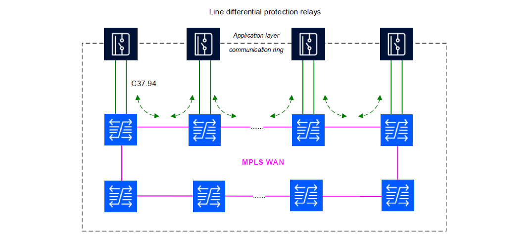
Figure 2.1 - Line differential protection communication with C37.94 via MPLS network
In Ethernet based communication case, the protection PDUs are sent within UDP/IP packets. The protection relays can be connected either directly or via an Ethernet LAN, e.g., the station bus, to the substation edge routers. VLANs can be used and are advantageous especially in the LAN case to prioritize the protection packets and isolate them from other traffic in the substation network. The Ethernet interface of the protection relays, supports the redundancy protocols High-availability Seamless Redundancy (HSR) and Parallel Redundancy Protocol (PRP), which are usually deployed in substation LANs. Figure 2.2 shows an example of four relays with Ethernet protection interfaces communicating via an MPLS network.
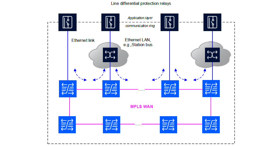
Figure 2.2 - IP over Ethernet line differential protection communication via MPLS network
There is a special scenario allowing seamless (uninterrupted) protection communication after link or node failure in the communication network. It is based on the end-to-end use of PRP between neighbouring relays. PRP is a Layer 2 protocol and therefore this scenario requires the deployment of virtual Ethernet links or virtual Ethernet LANs on top of MPLS in the wide area network. Two disjoint virtual links or virtual LANs are needed in the MPLS network. The substation edge routers should deploy doubled hardware components like line interface cards to avoid single-point-of-failure. Figure 2.3 shows an example network topology.
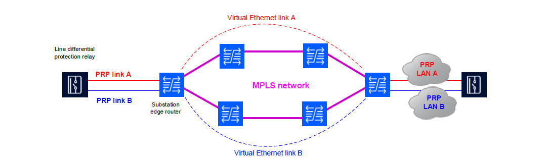
Figure 2.3 - PRP end-to-end redundancy via MPLS network
Each protocol packet is duplicated at sending relay and the duplicates are sent simultaneously over PRP link or LAN A and PRP link or LAN B. In error-free case both duplicate frames are received by the other relay via the separate paths. The first received duplicate is accepted for further processing but the second received duplicate is discarded. If one of the paths becomes interrupted as result of link or node failure, then the duplicates via the other path will still be received and the communication continues without any lost protocol packet.
High accurate and high available time synchronization is required for Ethernet based line differential protection communication. The DUTs support two alternative synchronization methods: 1PPS signal and IEEE 1588 Precision Time Protocol (PTP). The relays implement the IEC/IEEE 61850-9-3:2016 PTP Power Utility Profile and IEEE C37.238:2017 PTP Power Profile. The 1PPS signal and PTP synchronization must be provided by master clocks with primary time reference, e.g., GNSS.
The “ping-pong” synchronization protocol via the communication channel is not used with the protection relay Ethernet interface. The requirement of constant and symmetric delay with very low jitter can typically not be fulfilled by current packet-based wide area networks, even if methods like traffic prioritization and bandwidth reservation are applied.
In summary, these are the requirements of line differential protection relays under test to the communication network:
- High reliable communication with minimum corrupted and dropped frames or packets,
- High available communication with minimum network recovery time,
- As low as possible network delay (since it contributes to protection tripping time),
- Appropriate measures for traffic segregation and Quality of Service,
- Constant, symmetric network delay with minimum jitter in case of serial or TDM based protection communication,
- High accurate and high available time synchronization with 1PPS or IEEE 1588 in case of Ethernet based protection communication.
3. Communication network
Figure 3.1 below shows the physical network topology of the test setup. It consists of a field-deployed test network that is composed of 21 IP/MPLS nodes organized in Gigabit Ethernet access rings and a 10Gigabit Ethernet core ring. Functionally, this testbed is meant to behave identical to the deployed network.
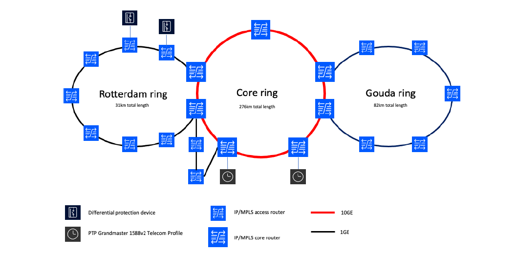
Figure 3.1 - Physical network topology of the test environment
The network is synchronized by means of PTP1588V2 from a grandmaster clock connected to core nodes in two different Data centres.
In order to speed up the process of locking the network nodes to the PTP sync master (i.e. in case of a node reboot), Synchronous Ethernet has also been implemented in the network. This provides additional frequency synchronization robustness to the IP/MPLS nodes.
There are two DUTs connected to two adjacent access routers using different interfaces, including a single C37.94 interface and dual Ethernet interfaces using optical cables.
The communication services between the relays are delivered through different types of MPLS services depending on the type of interface from the protection device which is connected to the router. For the C37.94 interface which requires an N x 64kb timeslot TDM (up to 12 timeslots) transport service from the network, it is necessary to create a Circuit Emulated (CE) point-to-point service (C-pipe) across the MPLS network.
For the Ethernet interface(s), a point-to-point Ethernet service is required from the MPLS network (E-pipe). Alternatively, a Virtual Private LAN Service (VPLS) or Virtual Private Routed Network (VPRN) service can be used also.
In order to provide a high degree of resilience to the protection function, two totally diverse paths have been created throughout the network for both the C-pipe and E-pipe services as depicted in Figure 3.2.
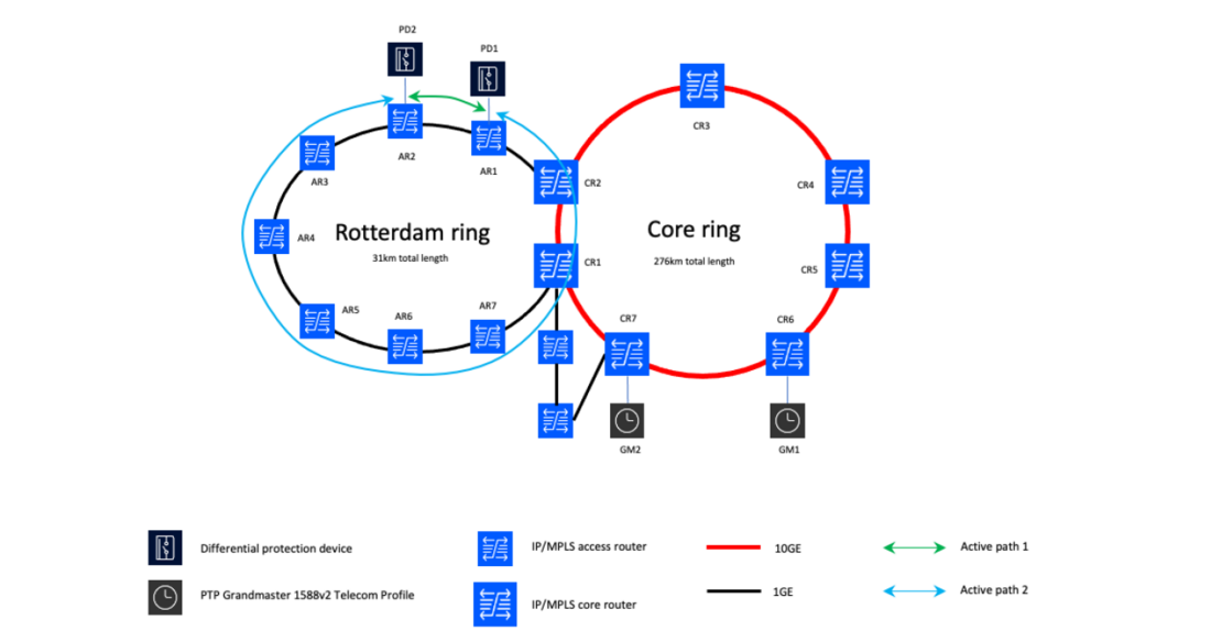
Figure 3.2 - Two diverse paths configured across the test network
3.1. Test case 1: Active/Active Multipath service for TDM based line differential protection services
The first test case consists of testing the redundancy of a differential protection service by means of a pair of single attached protection devices with a C37.94 interface to the IP/MPLS network. The network will provide two active connections between the protection devices across completely diverse paths. The test case consists of testing the robustness of the protection service under different failure scenarios:
- Link failure(s)
- Fibre cuts
- Congestion
- Node failures
- Port failures
- Card failures
- Entire router failures
The active connections between the protection devices consist of Circuit Emulation services, designed over strict hop paths. This means that there is no IP/MPLS control plane protocol which would optimize or re-route the path in case of problems such as link failures or congestion situations. This is why we refer to these paths as strict hop paths. Care needs to be taken to make sure that both paths are completely diverse and do not share links on their paths. The setup of this test case is illustrated in Figure 3. below. Active path 1 (C-pipe1) would be the shortest path between AR1 and AR2 while active path 2 (C-pipe 2) would be going over AR2, AR4, AR5, AR6, AR7, CR2 and CR1 to reach AR1.
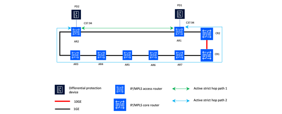
Figure 3.3 - Diverse Circuit Emulation circuits for the TDM data from the C37.94 interface
On the ingress side of the access router, the C37.94 data is first packetized and is then forwarded onto the two active paths towards the receiving node at the egress side of the differential protection service. At the egress side, two streams of packets are received. Given the inherent difference in length between path 1 and path 2, and possible link utilization between the different nodes, the packets arrive out of sequence on the egress side. This is where a combiner function will ensure proper ordering of the packets, discard duplicates and put the TDM data into the Jitter Buffer to ensure a smooth playout to the receiving side of the C37.94 interface. The Active Multipath principle of operation is illustrated in Figure 3..
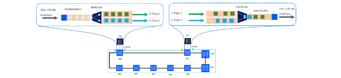
Figure 3.4 - Active Multipath principle of operation
When configuring the C-pipes on the IP/MPLS routers for this Active/Active service, care needs to be given to make sure the payload size and jitter buffer depth are configured in an identical manner and optimized for the longest path of the two.
Synchronization is very important for the TDM based service. In order to avoid any issues with synchronization, the nodes in the network are all synchronized using Synchronous Ethernet. (SyncE)
Synchronous Ethernet works in exactly the same way as synchronization of SDH/SONET and therefore is best suited for this kind of application. It’s important for SyncE to have a correct synchronization hierarchy which needs to be observed in order to avoid sync loops.
3.2. Circuit Emulation
Circuit Emulation is a standards-based methodology of transporting TDM data over a packet-based network (MPLS). There are two models of operation, the Circuit Emulation Service over Packet Switched Networks (CESoPSN – RFC5086) method which allows for structured transport of N x 64kb channels and there is the Structure Agnostic Transport over Packet (SATOP RFC 4553) model which allows a “transparent” transport of unstructured T1/E1 data.
As illustrated in Figure 3., the first step in the Circuit Emulation service is to get the TDM bitstream into the ingress port and create packets from this bitstream according to one of the two models described above.
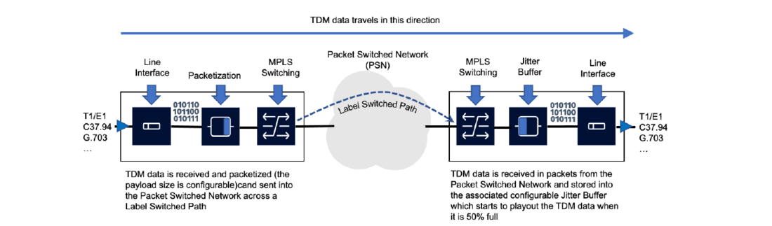
Figure 3.5 - Principles of operation of Circuit Emulation
Once the data it packetized, it will be sent across the packet network using Label Switched Paths (LSPs). With IP/MPLS there are multiple methods by which LSPs can be created. The first method of creating LSPs is ‘Static’, this means that the operator will need to manually configure the path, not governed by a control plane protocol. The second method to create LSPs is to use signalling. Signalled LSPs can be set up in two ways, either by using RSVP-TE (Resource Reservation Protocol-Traffic Engineering) using explicit-path LSPs or constrained path LSPs which rely on the CSPF (Constrained Shortest Path First) algorithm. LSPs can be protected by multiple standby paths which can either be manually pre-provisioned (active/standby paths) or through MPLS Fast Reroute (FRR), which is part of the RSVP-TE protocol. MPLS-FRR will automatically build several possible detour routes between the ingress and the egress nodes of an LSP, to protect against different failure scenarios.
For the line differential protection of Circuit Emulation service use case, it is recommended to use the RSVP-TE explicit LSPs with “Strict Hop” method and not allow any failover mechanism on the LSPs. The reason for this is that a switchover to a standby LSP may result in jumps in the latency which may be adversely affect the protection relays. The failover mechanisms (Active/Standby path or FRR) need time to detect the path failure (i.e. loss of signal – LOS on a fibre or missed BFD – Bidirectional Forwarding Detection) packets) before switching to the alternate path, which may take 50ms or more which is too long for the protection relays.
The payload size configuration and the jitter buffer depth configuration are the two key parameters which will have an impact on the performance of the Circuit Emulation service performance in terms of latency. The smaller we configure the payload size, the “faster” we will be sending packets across the MPLS network, hence the packets will be smaller. The smaller we configure the jitter buffer size, the faster it will start to playout data to the TDM interface. There is a balance to be observed between these two parameters. The smaller the payload size is configured, the more overhead will be created on the PSN, and the more bandwidth will be consumed. On the egress side, a small jitter buffer size increases the risk of packets being dropped due to buffer underruns or overruns.
3.3. Test Case 1 results
The tests have shown that the active-active multipath setup does provide a very good level of resiliency to the line differential protection devices. A failure in either path did not affect the performance of the protection devices, no errors were recorded. When both paths failed, the protection devices noticed a communication failure and the line differential protection function becomes blocked. This is expected behaviour. Other local protection schemes such as overcurrent, if present, continue to work as normal.
3.4. Test Case 2: Active/Active Multipath service for Ethernet based line differential protection services
In this test case we make use of the exact same equipment, except that the interfaces used at the level of the protection devices are based on Fast Ethernet (FE) fibre optic interfaces. The DUT have two physical FE ports but act as a single MAC. This means that it duplicates Ethernet frames across the two physical FE ports. Essentially, the DUT is providing a PRP function and requires two separate, diverse point-to-point Ethernet connections between two protection devices.
The way this is implemented on the IP/MPLS network is through the provisioning of two diverse E-pipe services as depicted in Figure 3.6 below.
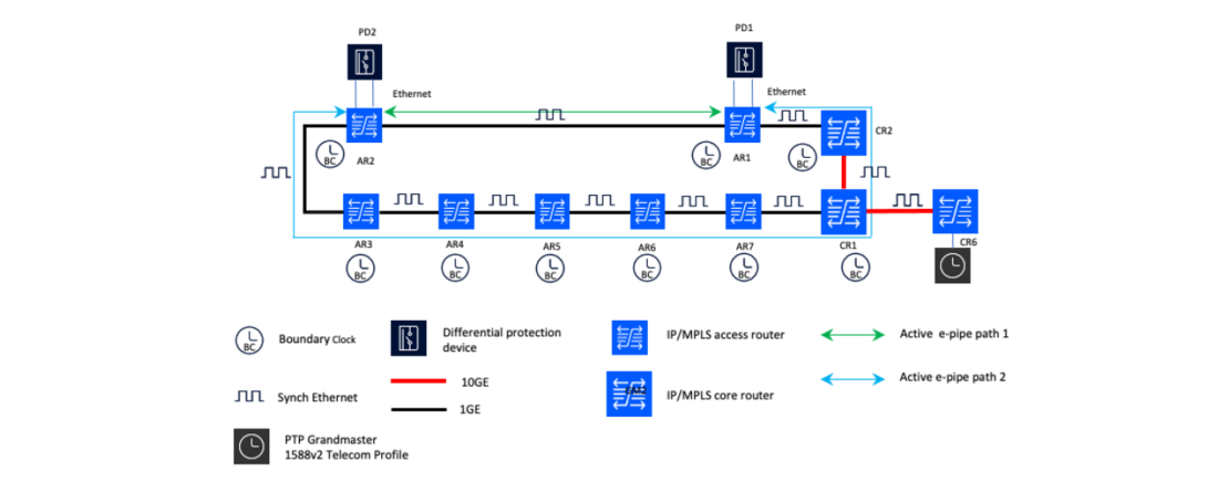
Figure 3.6 - Diverse path E-pipes configuration for the Ethernet interfaces
The IP/MPLS network to which the protection devices are connected to has been configured to use both SyncE and PTP for synchronization. PTP is used for time and phase synchronization while SyncE is there to provide greater robustness of the network synchronization at times of congestion, link and node failures as it will help the PTP nodes to synchronize faster to the master clock.
The IEEE 1588v2 standard has evolved over time and many different profiles have been developed. Most recently the Power Utility Profile has been defined to support specific power utility applications (IEC/IEEE 61850-9_3). This Power Utility Profile is based on L2 Ethernet services and has been conceived for station bus and process bus LAN implementations. It is not ideally suited for use across a wide area network. Wide Area Networks typically use the ITU-T G.8275.1 Telecom Profile for phase/time synchronization which scales very well across large networks. As part of this test scenario, we also wanted to validate the interworking between the PTP Telecom profile on the IP/MPLS network across the core and the access ring and the Power Utility profile on the Ethernet ports of the access routers connected to the protection devices as depicted below.
The routers in the access ring are all configured to be Boundary Clock nodes.
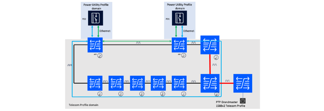
Figure 3.7 - Time synchronization configuration
The interworking between the Power Utility Profile on the Station bus and the Telecom Profile on the Wide Area IP/MPLS network is a specific feature of the IP/MPLS routers used in this setup.
4. Testing line differential protection
This chapter describes the different test setups used at the Stedin test facilities to perform the tests. The test network (network components and connections), as well as the devices under test (DUTs) are also described in this section. Furthermore, the different test cases are explained together with the reasoning behind the relevance and importance of these test cases.
4.1. The different test setups
There are four different test setups as depicted in the following figures Figure 4.1, Figure 4.2, Figure 4.3 and Figure 4.4. Two configurations are considered. A single attached relay configuration for the purpose of testing protection relays with a G.703 and C37.94 communication interface and a redundant attached relay configuration for new generation protection relays with an Ethernet/IP communication interface. Both configurations are connected firstly using a direct point-to-point fibre connection and secondly via the Stedin IP/MPLS Development Test and Acceptance (DTA) network.

Figure 4.1 - Test Setup 1 used in the configuration where single attached relays, equipped with a G.703 or C37.94 communication interface, are directly connected with a fibre optic cable
The test setups with the direct point-to-point connections (Figure 4.1 and Figure 4.2) are used to determine the trip behaviour of the Devices Under Test (DUTs) for both the single and redundant attached relay configurations. The purpose here is to capture the behaviour (differentiating behaviour and stabilizing behaviour) of the DUT. This ‘blue-print’ behaviour will be the reference behaviour (baseline) used for comparison purposes with all the other tests in which the MPLS DTAnetwork will be included. The DUTs are protection relays also known as Intelligent Electronic Devices (IEDs) equipped with differential protection functions.
In the two other test setups, the connections via the MPLS DTA-network are used to create Label Switched Paths (LSPs) between the two DUTs, in which the number of nodes can vary as well as the length of the connection. Also, main (primary) and backup (secondary) LSPs can be built to test different scenarios in order to provide redundancy and adequate failover mechanisms. In the case of a single attached relay, redundancy has been achieved by using the new Asymmetric Delay Compensation (ADC) multipath feature on the IP/MPLS routers, which provides seamless failover and switch-back functionalities. ADC multipath mode allows time division multiplex (TDM) traffic to be transmitted simultaneously over two paths from the near end of a C-pipe to the far end. This allows the traffic to switch paths in a hitless fashion while maintaining symmetry and experiencing minimal packet loss, Ref [03]. Regarding the dual attached relay, end-to-end seamless redundancy by frame duplication and duplicate elimination at the protection relays is used. The protection relays are configured with Parallel Redundancy Protocol (PRP), IEC 62439-3:2016 (Ref [04]) and doubleattached to separate Ethernet adapter cards at the access side of the IP/MPLS routers.
To simulate the High Voltage (HV) network, a universal relay test set and commissioning tool is used to inject three-phase currents in both relays. The trip signal is read from one of the relays. Three advanced differential test modules are used. Those 3 relevant test modules are added to a test file. To provide this test file, the DUT is first specified and set in Test Object. The relay settings as expected in the Stedin production environment are imported from the supplier protection tooling. After that the test hardware is set up in Hardware configuration. At this stage the number of channels and outputs required for the testing are configured. At least 6 current outputs and a trip command as binary input are required for the tests.
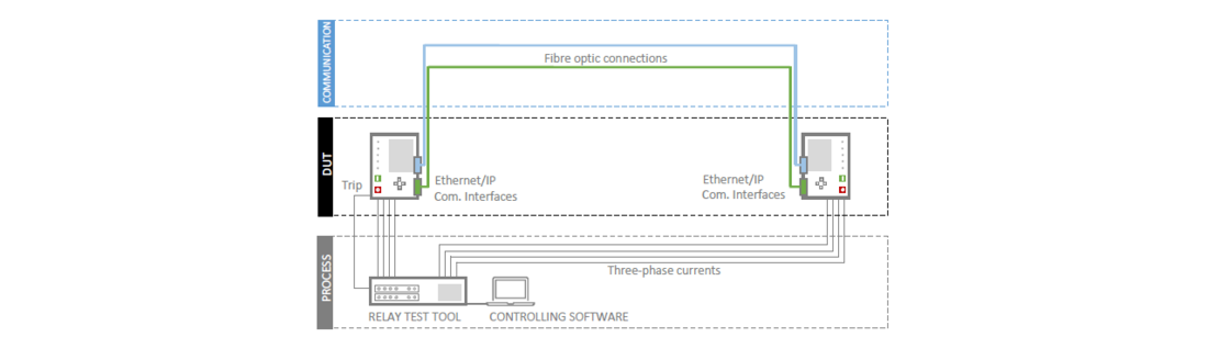
Figure 4.2 - Test setup 2 used in the configuration where redundant attached relays, equipped with two Ethernet/IP interfaces, are directly connected with two fibre optic cables
When considering the third test setup, as depicted in Figure 4.3, a few additional remarks can be made. De tests are performed with one LSP per direction, with one primary (main) and one secondary (backup) path. The secondary path could be pre-signalled (standby) or fast-reroute (FRR) one-to-one could be used.
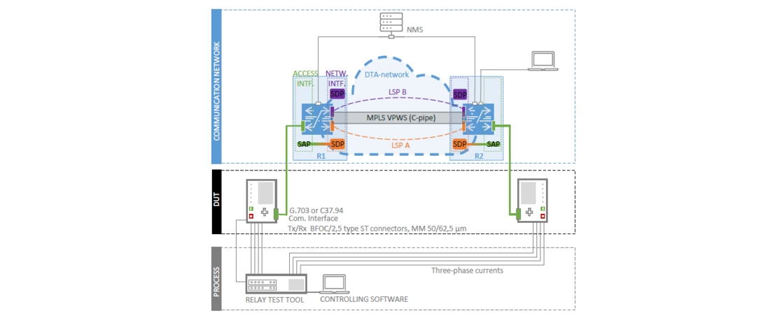
Figure 4.3 - Test setup 3 used in the configuration where single attached relays, equipped with a G.703 or C37.94 communication interface, are connected via the IP/MPLS DTA-network
For test setup 4 as depicted in Figure 4.4, MPLS Layer 1 services (virtual private pseudo wire service - VPWS) as well as Layer 2 services (virtual private LAN service - VPLS) are used to connect the relays.
The protection relays Ethernet interface(s) require a point-to-point Ethernet service from the MPLS network (E-pipe). Two E-pipe services are used here, with two LSPs for each direction having a primary but no secondary path. The E-pipe service consists of a Service Access Point (SAP) and a Service Distribution Point (SDP) pair, where one SDP is on the same router as the SAP, and the second SDP is on the far-end router. One SDP is related to the first LSP and the other SDP to the second LSP. The LSPs are configured to follow different physically separated routes. The SAPs could be configured VLAN-aware or transparent. Alternatively, a Virtual Private LAN Service (VPLS) have also been used.

Figure 4.4 - Test setup 4 used in the configuration where redundant attached relays, equipped with two Ethernet/IP interfaces, are connected via the IP/MPLS DTA-network
4.2. The test network and network components
4.2.1. Physical and logical topology
The test-network is depicted in Figure 4.5. This is Stedin IP/MPLS DTA-network, where all telecommunication devices and services are thoroughly tested and validated prior to an implementation in Stedin production communication network. It consists of twenty-two network components (MPLS-nodes) connected to each other in the physical topology as depicted in Figure 4.5. Three Gigabit Ethernet Edge-rings connected to a 10 Gigabit Ethernet Core-ring. Routers DT_01 and DT_02 are the two Edge-routers at the test location to witch the DUTs are connected. In the figure the length of the physical links between the DTA sites are also given. All the connections between the network components are optical fibres.
Different logical paths are created between the two routers by configuring Label Switched Paths (LSPs) on different routes as shown in Figure 4.6. In order to provide a high degree of resilience to the protection function, two totally diverse paths have been created throughout the network for both the C-pipe and E-pipe services. On top of the physical topology, a number of logical links are created for the purpose of testing. Figure 4.6 gives an overview of the possible paths that has been used in the DTA-network to perform the tests. The total length of some of the paths are mentioned here below:
- Direct: < 0,01 km
- Rdm_Edge: ~ 30 km (28,87 km)
- Rdm_Edge_Core: ~ 300 km (302,91 km)
- Rdm_Edge_Core_Gda_Edge: ~ 385 km (385,52 km)
The communication services between the relays are delivered through different types of MPLS services depending on the type of interface from the protection device which is connected to the router. For the C37.94 and G.703 communication interfaces which requires an N x 64kb timeslot TDM (up to 12 timeslots) transport service from the network, it is necessary to create a Circuit Emulated (CE) point-to-point service (C-pipe) across the MPLS network. For the Ethernet/IP communication interfaces an Ethernet pseudo wire (E-pipe) and a VPLS service are created.
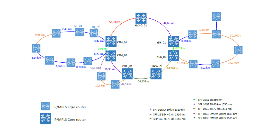
Figure 4.5 - Stedin IP/MPLS Development, Testing and Acceptance network (DTA-network) physical topology
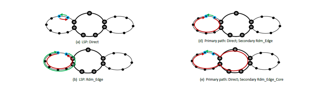
Figure 4.6 - The used paths in the DTA-network showing the different logical topologies during the tests
4.3. Test cases and test results
In this section the different test cases are explained together with the reasoning behind the relevance and importance of these test cases, Ref [06]. The testcases are arranged in the following three categories:
- DUT trip behaviour (baseline)
- DTA network configuration checks
- IP/MPLS tests
Figure 4.7 gives an overview of the performed tests.
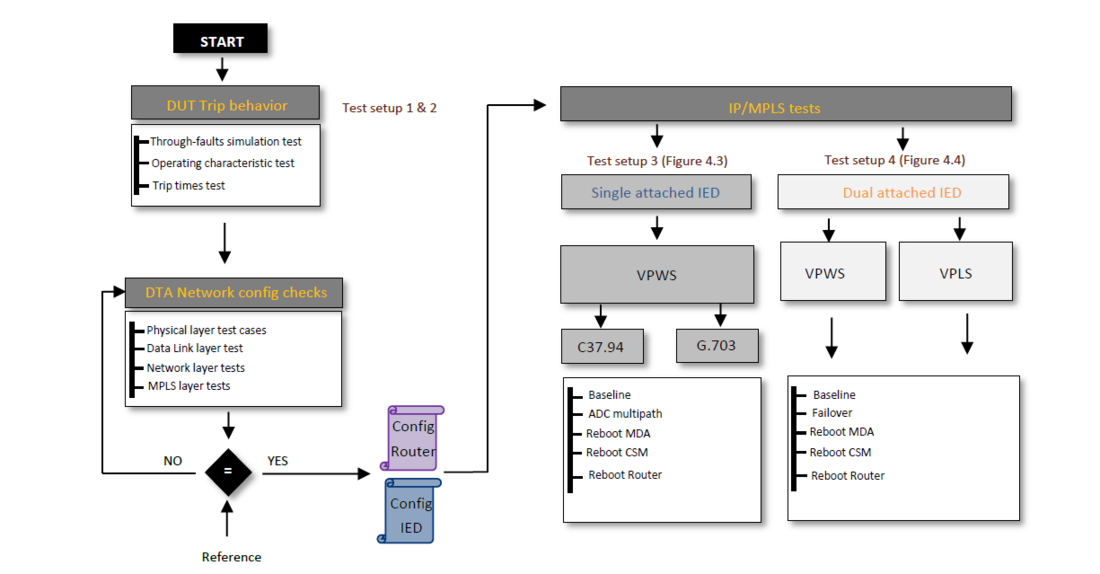
Figure 4.7 - Overview of all the performed test cases
4.3.1. DUT trip behaviour
The purpose of the first series of tests is to capture the behaviour (differentiating behaviour and stabilizing behaviour) of the device under test (IED/Protection Relay). This ‘blue-print’ behaviour will be the reference behaviour for comparison purposes with all the other tests in which the IP/MPLS DTA-network will be included. In order to capture the behaviour of the DUTs (IEDs) a series of pre-programmed automated tests are performed:
- Through-faults simulation: Confirmation of correct functioning and at the same time capture the behaviour of the DUT for faults outside the protected zone.
- Operating characteristic: Confirmation of correct functioning and at the same time capture the behaviour of the DUT for faults inside the protected zone.
- Trip times: Test and capture how fast the DUT trips depending on the differential current.
When the two relays are directly connected using only a multimode fibre cable between them, the operating characteristic is as shown in Figure 4.8.a.
The other two characteristics are obtained when the relays are connected via the IP/MPLS network for an E-pipe (Figure 4.8.b) and VPLS ( Figure 4.8.c) respectively and are almost similar. All the trips in the different configurations have occurred well within the allowed limits.
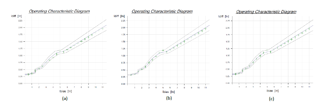
Figure 4.8 - Overview of all the performed test cases
4.3.2. DTA network configuration checks
The purpose of the second category of tests is to check and capture the network configuration used during the tests. The network configuration is captured for all the network oriented OSI model layers. Starting from the physical layer (OSI layer 1) up to the MPLS service layer. All used network components in the DTA-network are verified. The results of the configuration verification test cases show that the DTA-network is configured conform the Low-level design as expected.
4.3.3 IP/MPLS tests
Finally, the 3rd category tests involve the IP/MPLS DTA-network between the relays (IEDs) with different configurations according to the specific test case. The purpose of this series of tests is to assess the performance of the IP/MPLS network in comparison to direct fibre connections and verify the impact of the different possible MPLS fail over mechanisms on the protection services. The test results are summarized in the following.
Tests outcome, which did not comply with the requirements for the communication, was the IP/MPLS router Reboot test. This is because rebooting the IP/MPLS router takes longer than the maximum allowed recovery time of 50ms. The connection is lost when using PRP with only one IP/MPLS router. To mitigate this, a second IP/MPLS router at the same location can resolve this.
MPLS based services
The DUTs reported the degradation of one of the two PRP paths only when a local connection was severed. The DUTs did not report about this PRP degradation when a logical connection over the MPLS network was disconnected.
This result demonstrates that network is transparent to the DUT. Only an event directly impacting the access connection to the DUT influences the results. Internal behaviour, such as network re-routes, are transparent to the DUT and non-service affecting.
Legacy Interface over MPLS: Multi-path circuit
The test with the active-multipath feature, or hitless failover, has also been completed successfully. But the insights on the status of the active-multipath paths are not available. When configuring Active-Multipath the network admin needs to carefully calculate the amount of jitter on the network. When configuring the c-pipe with a jitter value which is too low, the failover will not be successful, and the disconnection of the primary interface will result in loss of communication. There was no way, or no way known, available to see if all paths which were configured was participating in the active-multipath successfully.
It was also observed that when a fibre was disconnected in the active multipath configuration the communication between relays was not affected. It was only after re-establishing the physical link and disconnecting the second link immediately thereafter, the communication between the RTUs fail.
This shows the importance of checking that the network is in a ready state before a test procedure is executed. Just as a live network in a stable state before a failure occurs, it is important to monitor the starting state of the network between two tests or repeat of a test.
5. Conclusion and recommendations
Stedin Telecom wants to improve and optimize the performance of the data communication services for the tele protection devices over the IP/MPLS network. The purpose of the tests performed is to proof that a functioning stable point-to-point connection can be established on the IP/MPLS network that meets the requirements for protection devices. Another purpose of the tests was to investigate which resiliency mechanisms can be deployed between two endpoints to provide seamless failover and “revert back” mechanisms on the IP/MPLS network without impacting the service.
This paper covers the issues encountered and how they were addressed when trying to attain end-to-end synchronization. Both IEEE C37.94 and Ethernet/IP based line differential protection communication were considered. Both platforms tested, “PRP over disjoin network paths” and “legacy interface over active-multi-path (MPLS)”, produced working functional solutions for differential tele protection. However, since these were essentially “black-box tests”, follow-on tests should focus on protocols used by the solutions and their interactions with the network environment. There also should be further investigation of procedures and tooling for both service turn-up, operations and management.
In case of migration from legacy SDH to modern packet-based networks, the tested line differential protection relays can be connected to e. g., MPLS network edge nodes without any hardware or firmware changes. The protection communication transport by help of TDM circuit emulation requires careful planning, configuration and monitoring of the MPLS network. The main focus is on accurate and reliable synchronization of the TDM circuit emulation endpoints, this means the network edge nodes, and constant and symmetric channel delays. Appropriate measures should be implemented so that the MPLS network provides a high level of quality of service and availability, comparable to that of the previous SDH network.
The new native Ethernet and IP based protection interfaces of the tested line differential protection relays allow smooth integration into substation Ethernet LANs and MPLS WANs. The legacy TDM interfaces are not used further, with the benefit of potential CAPEX and OPEX savings. Purely looking at the price per port of C37.94 interfaces compared to Ethernet interfaces, it becomes clear that Ethernet offers better price points, higher density and simpler provisioning and management capabilities. The challenging TDM circuit emulation, with possible network delay jumps and asymmetry in channel delays, is not needed anymore. The end-to-end packet-based communication results in lower network delay, which contributes to lower protection tripping time. The Ethernet and IP-based protection communication also requires appropriate quality of service and availability measures in the MPLS network. A major topic is the accurate and reliable synchronization of the protection relays.
References
- Physical/electrical characteristics of hierarchical digital interfaces, ITU-T Standard G.703, April 2016.
- IEEE Standard for N times 64 kbps Optical Fiber Interfaces between Teleprotection and Multiplexer Equipment, IEEE Standard C37.94-2017, March 2017.
- 7705 SAR Services Guide R22.4.R1
- International Electrotechnical Commission IEC 62439-3:2016 Industrial communication networks - High availability automation networks - Part 3: Parallel Redundancy Protocol (PRP) and High-availability Seamless Redundancy (HSR)
- SIP5_7SA-SD-SL-VK-87_V08.60_Manual_C011-F_en
- USTELECOM-DES-TE-RAP01-0008_1.0_2_publication_STN-Linedifferential_Protection_over_STEDIN_IP-MPLS_DTA_network_-_SIEMENS_-_NOKIA-RPT