Line Protective Relays Suitable for Systems With a High Penetration of Unconventional Sources – Operating Principles and Field Experience
B. KASZTENNY - Schweitzer Engineering Laboratories, Inc., USA

Summary
This paper describes a new line protection scheme suitable for systems with a high penetration of renewable sources. The presented scheme does not use weak-infeed logic and transfer tripping predicated on one terminal being strong. Instead, it assumes that unconventional, and typically weak, sources drive the fault current at all line terminals. Further, the paper does not assume that the sources comply with any present or pending fault current contribution standards. The scheme operates based on fault-induced transients (traveling waves and fast incremental quantities), which are principally independent of the source’s fault current response.
The transient-based protection principles presented in this paper were implemented in 2017 in a high-performance, fully digital, ultra-high-speed (UHS) line protective relay. These relays have been in service since then, including in systems with a high penetration of unconventional sources. To date, the relays have accumulated significant field experience. The field data fully validate the new relay design including security, in general, and dependability including in applications near unconventional sources. The relays routinely trip on the order of 1 to 5 ms, reducing the fault clearing time to 1.5 cycles when using two-cycle circuit breakers. This fast operation brings an additional benefit of increasing transient stability margins in systems with unconventional, and therefore low- or no-inertia, sources.
The presented scheme comprises the full range of line protection functions, from primary protection for line faults to remote backup protection for adjacent substations and lines. A built-in traveling-wave fault locator provides excellent fault-locating accuracy, regardless of the source, system, and fault characteristics.
The paper briefly explains the protection principles, discusses application factors, and presents field cases.
Keywords
Line Protection, Inverter-Based Sources, Traveling Waves, Incremental Quantities, Transient-Based Protection, Ultra-High-Speed Protection1. Introduction
Fault characteristics of unconventional energy sources (wind-powered rotating machines and inverter-based sources) are not only different than those of synchronous generators, but they also may change over time. Unconventional sources have been evolving and will continue to change because of technological improvements, to meet new grid requirements, and because of software upgrades for internal optimization, life extension, or to address quality issues. Unless and until the unconventional source characteristics are standardized, a sound approach to protective relaying near unconventional sources is to not attempt to discover and use characteristics of the unconventional sources but to devise protection principles that are as independent from the source characteristics as possible [1].
The unusual fault response of unconventional energy sources affects line protection principles. However, because power transformers, buses, capacitor banks, reactors, and synchronous generators use unit protection for short-circuit protection (such as differential schemes), the negative impact of these power system elements on protection is limited. Therefore, the two main areas of concern are line protection and remote backup protection.
In this paper, we describe transient-based line protection principles that use traveling waves and fast incremental quantities. We briefly introduce the underlying principles and explain why these protection methods work well in systems with unconventional sources. We share several field cases to illustrate the concepts, summarize the field experience, and discuss practical limitations of these line protection methods.
The paper also discusses backup protection for line faults as well as remote backup protection for out-of-zone system faults. In this respect, we discuss simplifications to the distance elements that make them dependable in applications near unconventional sources. We also recommend a shift in protection philosophy from remote backup to local backup.
2. Transient-Based Line Protection
Transient-based line protection responds to short-lived signal features in the relay input currents and voltages. Fault-generated transients are not powered by the sources present in the system but by the energy stored in the inductance and capacitance of the system components prior to the fault, primarily in transmission lines. To understand this key factor, consider a Thevenin equivalent network during faults. In the Thevenin network, all equivalent sources are removed, and their terminals are shorted. The change in voltage at the fault point is the source that drives all the incremental signals in the network [2]. This independence of the fault signal components from physical sources has been valued in protective relaying for decades, long before the days of wind-powered generators and inverter-based sources. It facilitates fast protection that is independent from the load and infeed effects. Transient-based protection is also largely independent of the fault characteristics of the sources – a key feature appreciated today because of the unusual fault response of unconventional sources.
2.1. Field Example
Fig. 1 shows the currents and voltages recorded at the terminals of a 40 mi 345 kV 60 Hz transmission line for an internal C-phase-to-ground fault. Transient-based line relays [3] asserted their trip commands in 0.8 ms and the two-cycle SF6 circuit breakers interrupted the fault in about 23 ms for a total fault clearing time of 24 ms (1.5 cycles). The traveling-wave differential scheme (TW87) operated first (0.8 ms). The permissive overreaching transfer trip (POTT) scheme operated second at about 2 ms into the fault. The POTT scheme works with the traveling-wave (TW32) and incremental-quantity (TD32) directional elements, which asserted in 0.1 ms and 1.5 ms, respectively. This installation uses a direct (point-to-point) fiber protection channel with an end-to-end latency of 0.35 ms.
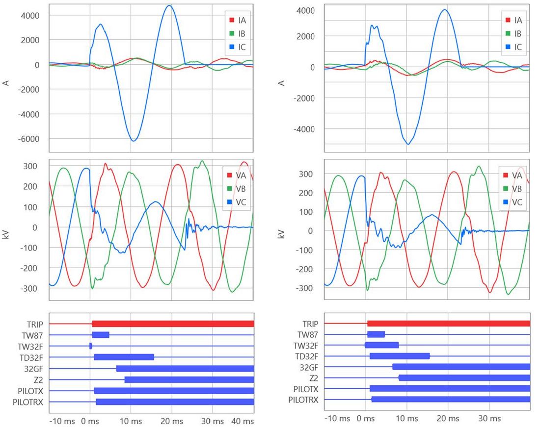
Figure 1 - Current, voltage, and relay bit records at both terminals for an internal CG fault
The fault in Fig. 1 occurred on a line connected to relatively strong sources dominated by synchronous generators. However, it becomes self-evident that the relays did not trip in response to the fault current supplied by the sources. The TW87 scheme requires remote data to operate. Because the remote data arrive after a 0.35 ms delay and the scheme operated in 0.8 ms, the TW87 scheme acted upon not more than 0.80 ms – 0.35 ms = 0.45 ms of remote data. No source can change its current much in half a millisecond. The TW87 scheme responded to fault-generated transients, specifically the traveling waves (TWs).
2.2. Traveling Waves
Fig. 2 shows the faulted-phase local (IC) and remote (ICR) currents recorded at 1 Msps for the fault in Fig. 1. The faulted-phase currents exhibit a series of sharp changes with varying magnitudes and polarities that occurred at certain times relative to the fault inception time. The ringing visible in the current signals is an artifact of the frequency response of current transformers (CTs) and control cables. The relays filter out this ringing to reveal the polarity, timing, and magnitudes of the sharp changes visible in the currents. These sharp changes in the currents represent the current TWs as they arrive at the line terminals, partially reflect from the terminals, arrive at the fault and other discontinuities, further reflect, and arrive back at the line terminals. These measured current TWs are the sums of the incident and reflected TWs because the CTs naturally measure total TWs. You can think of the signals in Fig. 2 as “natural fault-induced communications signals.” The polarity, timing, and – to a lesser degree – magnitudes of these TWs “communicate” the fault information to the relays (internal fault, external fault, and distance to fault).
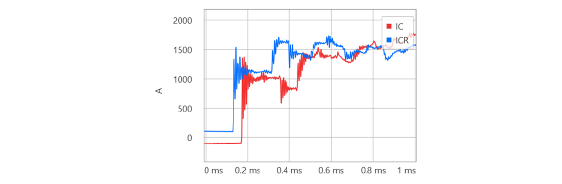
Figure 2 - Local (IC) and remote (ICR) faulted-phase currents recorded at 1 Msps for the case shown in Fig. 1.
Fig. 2 shows that the TWs that arrive at the line terminals contain an enormous amount of information. Considering the physical phenomena responsible for TW generation and propagation (a fault launching TWs toward the line terminals and TWs transmitting, reflecting, attenuating, and dispersing in the system), we conclude that this information is very reliable, little dependent on the system and fault conditions, and difficult to distort. Observe the following aspects of TW behavior to better understand the potential of TWs for line protection [2]:
- The first TW that arrives at a line terminal following a fault must come from the fault and cannot be a reflection.
- A fault that occurs when the voltage at the fault point is positive sharply reduces the voltage and launches negative current TWs in both directions. Therefore, the first current TWs at both line terminals must have the same polarity and that polarity must be consistent with the pre-fault voltage polarity.
- TWs travel on overhead lines at a well-defined velocity of about 98 percent of the speed of light in free space and therefore will arrive at the line terminals after a predictable and consistent delay. TW arrival time cannot be distorted by the system and fault characteristics. For example, if a TW launched by an external fault entered the line at one terminal, it must leave the line at the opposite terminal after the end-to-end TW propagation time specific to the protected line.
- Termination impedances do not change during the first few milliseconds of a fault. TWs reflect off and transmit through various discontinuities such as the line terminals and the fault in a consistent manner. The TW polarities cannot be distorted by the system and fault characteristics.
A relay that compares TW arrival times and polarities uses information that is almost entirely independent of the system and fault conditions. Multiple TWs arrive at the line terminals. Many of these TWs encode information about the fault location. As a result, a TW-based line protective ultra-high-speed (UHS) relay such as [3] or [4] acquires a wealth of information about the fault and therefore can operate securely in as fast as a few milliseconds.
By contrast, traditional relays operate based on the fundamental frequency voltages and currents. Attempting to measure the fundamental frequency voltage and current magnitudes and angles in a few milliseconds would yield extremely inaccurate results and would lead to relay misoperations. TW-based relays, however, do not attempt to quickly measure the fundamental frequency voltage and current magnitudes and angles, but instead, they use very different and previously untapped information encoded in the transient components of the relay input signals.
2.3. Incremental Quantities
Incremental quantities are changes in voltages and currents relative to their expected values if there were no fault. Typically, they are obtained by subtracting the pre-fault values from the fault values. In some applications, they are obtained by using high-pass filters to magnify changes in the voltages and currents at the fault inception time. Fig. 3a shows the C-phase incremental voltage (DVC) and current (DIC) for the case shown in Fig. 1, obtained by subtracting the pre-fault values as implemented in UHS relays [3] and [4].
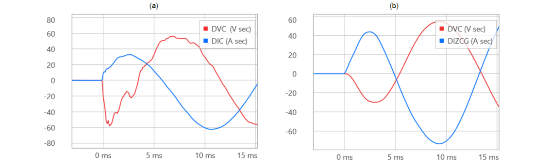
Figure 3 - C-phase incremental local voltage and current for the case in Fig. 1: instantaneous incremental signals (a) and low-pass-filtered voltage and replica ground loop current (b)
The incremental voltage and current may be low-pass filtered as shown in Fig. 3b to remove the impact of line charging current so that the relay operating principles can treat the protected line as a resistive-inductive (RL) circuit. Fig. 3 illustrates that the relative polarity of the change in voltage and current encodes the fault direction. For a forward fault, the changes in voltage and current have opposite polarities (Fig. 3a); for a reverse fault, the changes in voltage and current have the same polarity. Note that this directional information is available to the relay after a very short time – on the order of 1 ms when using incremental quantities. Because the fault direction determination can be made so quickly, the relay operates irrespective of the source’s response to the fault. Fig. 3b shows the low-pass-filtered incremental voltage (DVC) and the incremental replica current (DIZCG) for the CG measurement loop. These two signals maintain the opposite polarity relationship beyond the first few milliseconds. The replica current (iZ) is equivalent to a voltage drop – caused by the line current (i) – across a 1 Ω impedance that mimics the line impedance (Z):
(1)
The Incremental Quantity Directional Element section provides more information about the replica current.
3. Traveling-Wave Differential Scheme
The TW87 scheme uses the following operating principle [2]–[4]:
- During an internal fault, the first current TWs at the line terminals arrive less than the end-to-end TW propagation time apart. The arrival time difference allows the scheme to determine the fault location and use it to obtain the pre-fault voltage at the fault location.
- During an internal fault, the first current TWs at the local and remote line terminals have matching polarities and that polarity is consistent with the polarity of the prefault voltage at the fault location.
- During an external fault, a current TW that enters at one line terminal leaves at the opposite line terminal after the end-to-end TW propagation time. Because the polarities of the CTs are oriented toward the line, the first TW that enters at one terminal and the exit TW that leaves at the other terminal have opposite polarities.
- Before the scheme operates, it verifies that the aerial mode current TWs are significantly higher than the ground mode current TW. This condition secures the TW scheme for TWs induced by lightning strikes. • Before the scheme operates, it verifies that the current TW signals are robust in terms of magnitude and shape and therefore can be reliably used for tripping.
- Before the scheme operates, it verifies that the currents exhibit changes in the power frequency spectrum. This condition secures the TW scheme for high-frequency signals induced by switching in the primary system, coupling to the control cables, and lightning strikes.
Of course, the TW87 scheme requires access to high-fidelity time-synchronized remote currents (1 Msps sampling rate, 1 μs time alignment accuracy). Our implementations in [3] and [4] use a direct fiber channel to exchange the data at over 100 Mbps and time align the data to less than a 0.2 μs difference without reliance on satellite clocks.
4. Permissive Overreaching Transfer Trip Scheme
An ultra-high-speed directional comparison protection scheme must be a permissive (not a blocking) scheme because of the following reasons:
- The transient-based directional elements provide a transient (not a persistent) fault direction indication (they assert and quickly reset when the transients subside). Because they reset, they do not provide a persistent blocking signal during external faults.
- The transient-based directional elements have a finite dependability and therefore cannot be trusted for dependable blocking during external faults.
- Blocking schemes require time coordination and the coordination delay defeats the purpose of ultra-high-speed tripping.
- Permissive schemes are inherently more secure than blocking schemes. This characteristic is important when reducing trip times to just a few milliseconds.
Our implementations in UHS relays [3] and [4] use a POTT logic with the traveling-wave and incremental-quantity directional elements [2]. UHS relays [3] also include fundamental frequency component-based directional elements for dependability. The POTT scheme can be used with any protection channel, but preferably with a low-latency digital channel such as direct fiber or a time-division multiplexed protection-grade channel over the IEEE C37.94 relay-to-multiplexer interface.
4.1. Traveling-Wave Directional Element
The TW32 element operates based on the polarity of the first current TW relative to the first voltage TW. For a forward fault, the polarities are opposite; for a reverse fault, the polarities are the same. Fig. 3a illustrates this principle in general, while Fig. 4 provides a plot that zooms in on the initial 100 μs of data following the first TW arrival time.
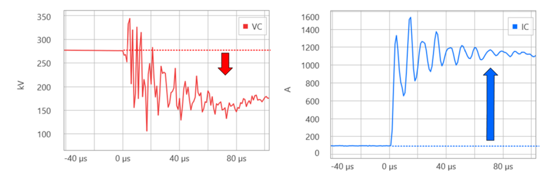
Figure 4 - The first 100 μs of the C-phase voltage and current for the fault shown in Fig. 1
Our implementations in [3] and [4] are based on an integrated torque obtained from the voltage and current TWs [2]. The TW32 element is extremely fast (the operating time changes very little with system conditions and is about 0.1 ms). It is secure (it never asserts in the forward direction for a reverse fault) but not fully dependable (it may not assert in the forward direction for a forward fault, and it may not assert in the reverse direction for a reverse fault). Combined with a direct fiber channel, the TW32 element provides trip permission that is sent in about 0.1 ms and received at the remote relay in about 1 ms.
The following factors impact TW32 dependability:
- As illustrated in Fig. 4, voltage transformers (VTs) are not high-fidelity sensors. They reproduce the polarity of the initial voltage TW but not its magnitude or accurate arrival time. They may attenuate and delay the initial voltage TW impacting the TW32 dependability (a delay means a group delay of the VT understood as a low-pass filter; the current in Fig. 4 shows a sharp change, while the voltage shows a ramp that lasts about 60 μs).
- In applications to short lines, shortly after the incident TW that originated from a reverse fault passes through the line terminal, a TW can arrive reflected from the remote terminal. The two TWs can partially overlap and confuse the TW32 logic. Our implementations in [3] and [4] do not allow TW32 applications on lines that are shorter than about 15 km (10 mi).
Also, “fault direction” is an ambiguous term. In a meshed network, an external fault is simultaneously forward and reverse (one can trace the path from the relay to a fault in the direction of the CT polarity markings, and one can trace the path from the relay to a fault in the direction opposite of the CT polarity markings). Various directional elements may assert differently for an external fault because they use different electrical measurements. This known issue [5] can be solved by either using separate permissive signals for each of the directional elements applied or adding a blocking logic inside the POTT scheme. Because the TW32 element is not fully dependable, the blocking option is not available to us, and using a separate permissive bit for the TW32 element is the option in UHS relays [3] and [4]. As a result, applications that use the TW32 element in the POTT scheme typically use digital channels that can carry multiple permissive bits – one for the TW32 element (PILOTRXW in Fig. 8) and the other (PILOTRX in Fig. 8) for other directional elements used in the POTT scheme.
4.2. Incremental-Quantity Directional Element
The TD32 element operates based on the relative polarity of the incremental voltage and current. During the first 1 to 2 ms of the fault, the network inductance opposes the rise in the current to the level determined by the short-circuit capacity of the system. As a result, the initial change in the current is limited in magnitude but is relatively sharp because it is driven by the resistance and capacitance of the network (Fig. 3a). During that initial stage of the fault, the incremental voltage and current have opposite polarities for a forward fault and matching polarities for a reverse fault. Later, however, the inductive nature of the circuit starts to dominate, and the relative polarities of the incremental voltage and current no longer encode the fault direction. Instead, the relative polarities of the incremental voltage and the incremental replica current encode the fault direction (Fig. 3b). Our implementations of the TD32 element in [3] and [4] use an integrated torque developed from the incremental voltage and current [2]. Initially, the incremental voltage and current are used to capture the relationship illustrated in Fig. 3a. After the initial period of about 1 ms, the TD32 logic switches to the low-pass-filtered incremental voltage and incremental replica current to maintain the fault direction discrimination as illustrated in Fig. 3b. The initial boost from the fast incremental voltage and current provides an additional security margin, and at the same time, it speeds up the TD32 operation.
5. Field Experience
The transient-based UHS line protective relay [4] was released in 2017. A version [3] with embedded backup functions based on fundamental frequency components was released in 2020. At the time of this writing, the two UHS relays have accumulated a few thousand relayyears of field experience. The field experience is very positive and can be summarized as follows:
- The transient-based protection elements and schemes are secure. Because the transient-based relays are simpler to use, settings errors are reduced and, as a result, the relays perform better in the field than the previous generation of relays.
- The transient-based protection elements and schemes are highly dependable. The POTT scheme based on the TD32 element is the workhorse of transient-based line protection. The POTT scheme operates for all practical line faults as long as the system is in a steady state before the fault.
- The transient-based protection elements and schemes are very fast and trip on the order of 1 to 5 ms. The relays operate fast regardless of the types of sources in the system.
- Circuit breakers that are rated for two-cycle operation typically clear faults in 1.5 cycles if actuated in 1 to 5 ms. As a result, the total fault clearing time is between 1.5 and 2 cycles.
- The TW-based fault locator embedded in the relays performs exceptionally well. It is highly dependable and has a field-proven accuracy of about one tower span (300 m or 1,000 ft) regardless of the line length, fault resistance, and system conditions, including source type.
- The TW-based protection elements and schemes are dependable but not 100 percent dependable. The Transient-Based Line Protection Limitations section elaborates on the dependability of these elements and schemes.
Fig. 5 through Fig. 8 show fault records for a few field cases in a 60 Hz system including different voltage levels, line lengths, fault types and resistance, and source characteristics. The transient-based UHS relays [3] and [4] operated in only a few milliseconds, resulting in a fault clearing time shorter than 2 cycles. The figures illustrate the speed and dependability of the TD32 element. It allows the POTT scheme to operate on the order of 2 to 4 ms when used with a low-latency protection channel: see the PILOTRX signal (trip permission received) in Fig. 1 and the TRIP signal in Fig. 5 through Fig. 8. Fig. 5 illustrates a case of a fault current supplied by wind-powered generators (Type III). The current does not increase significantly, and it is squelched in about 1 cycle, after which it contains mostly the zero-sequence current coming from the grounded neutral of the interconnecting power transformer.
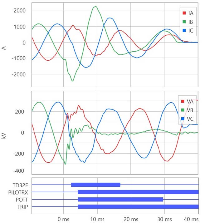
Figure 5 - Field case 1. BG fault cleared in 2 cycles
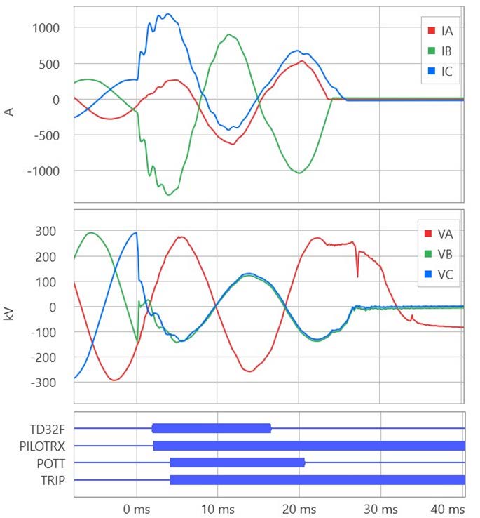
Figure 6 - Field case 2. BC fault cleared in 1.4 cycles
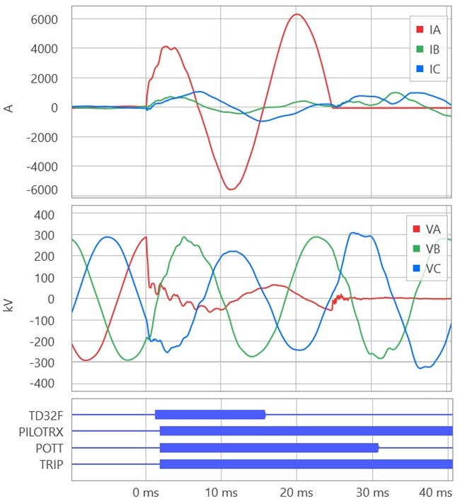
Figure 7 - Field case 3. AG fault cleared in 1.5 cycles
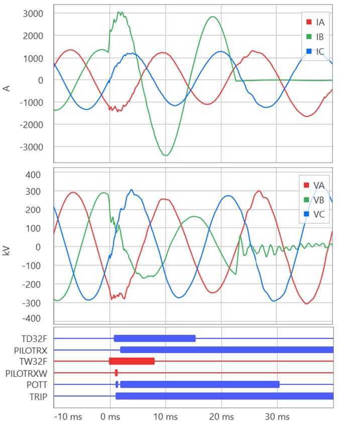
Figure 8 - Field case 4. BG fault cleared in 1.4 cycles
6. Transient-Based Line Protection Limitations
Transient-based protection principles implemented in UHS relays [3] and [4] proved to be dependable. The six years of field experience at the time of this writing allow us to make the following observations:
- Operating based on transients, protection elements and schemes require the system to be in a steady state for a few cycles prior to the fault. Transients that occur shortly before an internal fault may limit dependability but will not cause any security issues. Similarly, a second fault (an evolving fault) that occurs after more than about half a cycle but before about 3 cycles may not be detected properly. Also, the transient-based protection principles are not applicable to the switch-onto-fault (SOTF) logic.
- Practically, the occurrence of faults at the voltage zero crossing is impossible. A certain minimum voltage is required to break down the isolation. Given that the isolation withstood the full system voltage a quarter of a cycle prior to the zero crossing, it is unlikely the isolation will break down when the voltage is near zero. That break-down voltage may be small in proportion to the nominal voltage, but it is still on the order of tens of kilovolts. A change in voltage that is tens of kilovolts launches TWs that can be reliably measured and used for protection and fault locating.
- The TD32 element is very sensitive, fast, and dependable. It operates for a wide range of system and fault conditions as long as the system is in a steady state for a few cycles prior to the line fault. As a result, the POTT scheme is both fast and dependable.
- Dependability of TW-based elements and schemes can be limited by a poor frequency response of CTs and control cables. The relays intentionally block TW-based protection if they detect excessive ringing in the 1 Msps signals. The TW-based protection may have low dependability when used with unshielded CTs and cables.
- Dependability of TW-based elements and schemes is limited on short lines and when the internal fault is located very close to a line terminal (1 to 2 km) or close to a line tap, if present. See [6] for an in-depth discussion on dependability of TW-based protection and fault locating.
- Dependability of TW-based elements and schemes is limited when the protected line terminates on a power transformer or autotransformer with no other lines or capacitor banks connected to the line terminal. This high surge impedance termination prevents the relay from measuring current TWs (TWs reflected from an infinite termination impedance cancel the incident TWs, resulting in the total current TW in a CT of zero). However, these applications present an opportunity to apply the TW overcurrent element, TW50. See [7] for more information.
- High-resistance faults do not cause the fault-point voltage to change much. As a result, only small TWs are launched, and the TW-based protection may not operate. However, the TD32 element is sufficiently sensitive to such faults, resulting in both fast and dependable POTT operation.
- The TD32 element is dependable in applications near unconventional sources. It has a very high dependability margin in applications near wind-powered generators and good margin in applications near inverter-based sources. In the latter case, the TD32 element may require a timer to extend its initial forward assertion to maintain the POTT scheme dependability. See [8] for an in-depth discussion on dependability of the TD32 element in these applications.
7. Backup Protection for Line Faults
The available field experience with transient-based UHS relays [3] and [4] proves they have a high, but not perfect, protection dependability. The following fundamental frequency component-based protection elements and schemes complement transient-based protection, resulting in full dependability:
- In applications near strong sources, overreaching distance elements (Zone 2), ground directional elements (32G), and negative-sequence directional elements (32Q) provide backup for the TW32 and TD32 elements within the POTT scheme (see Fig. 1 for illustration).
- In applications near unconventional sources, the 32G element is dependable because the interconnection transformers supply the zero-sequence current during ground faults. You can also count on the ground distance protection for backup (Zone 1 instantaneous trip and the Zone 2 operation through the POTT scheme).
- Offset distance elements (directly tripping Zone 1 and Zone 2 in the POTT scheme) described in [8] provide backup for both ground and phase faults in applications near unconventional sources.
- The line current differential (87L) scheme provides dependable and secure line protection. The 87L scheme is secure. Enable the phase (87LP), ground (87LG), and negative-sequence (87LQ) differential elements for better dependability without diminishing security [9].
- Time-coordinated ground overcurrent and distance elements provide backup for ground faults for the contingency of losing a protection channel.
- Time-coordinated offset phase distance elements [8] provide backup for phase faults for the contingency of losing a protection channel.
This protection philosophy can be accomplished by using two relays as follows:
Relay 1, such as [3], provides transient-based protection, including TW87 and POTT schemes, distance and overcurrent backup, SOTF logic, and TW-based single- and doubleended fault locating.
Relay 2, such as [10], provides fundamental frequency component-based protection, including an 87L scheme, permissive and blocking directional comparison schemes, distance and overcurrent backup protection elements, SOTF logic, autoreclosing and breaker failure protection, TW-based double-ended fault locating, bay control, and many other functions.
8. Backup Protection for System Faults
Traditionally, line protective relays provide remote backup protection for system faults that are one or two buses away. Remote backup is an attractive protection philosophy because it is more economical than local backup and it works under the worst-case assumption of the loss of control power at the affected substation. Provided by time-coordinated phase and ground distance and ground overcurrent elements, remote backup protection faces challenges in applications near unconventional sources. These challenges arise from the following factors [8]:
- Low source inertia challenges the concept of memory polarizing for mho distance elements, especially the phase elements that do not benefit from the zero-sequence current fed by the interconnection transformers, and especially when time-delayed tripping is applied, exposing the distance element to swings before the timecoordination timers expire.
- Low source inertia changes the static infeed effect into a dynamic infeed effect (a fault combined with a power swing) where the ratio of the remote to local current changes its phase angle, resulting in substantial underreach (Zone 2) or overreach (Zone 1), especially when time-delayed tripping is applied.
- Unusual negative-sequence current challenges the concept of polarizing the phase quadrilateral distance elements with the negative-sequence current.
- Unusual negative-sequence current challenges the traditional current-based faultedloop selection in distance protection elements.
Reference [8] describes a simple and practical solution for step-distance remote backup protection. The solution is based on the following key elements [8]:
- Memory polarizing is eliminated and replaced with an offset impedance characteristic (reverse offset is used to include the local bus and the beginning of the protected line inside the zone of protection). Time coordination ensures selectivity for reverse faults.
- A forward offset can also be used to provide an optimum operating characteristic around the remote bus with more margin for the dynamic infeed effect caused by the low source inertia.
- Undervoltage faulted-loop selection replaces the current-based logic.
This solution is simple to understand, test, and apply. Effectively, it is a simplification of typical distance protection logic, not an extension that adds complexity. Moreover, the above solution used to be practiced out of necessity in the early days of electromechanical-based distance relays and worked satisfactorily.
Of course, the time-coordinated ground overcurrent relays provide backup protection because of the zero-sequence current from the interconnecting transformers. Also, a pivot toward the local backup philosophy is a prudent approach (full duplication of relays, channels, and control power; breaker-failure protection; direct transfer tripping; enhanced monitoring of relays, trip coils, control power, and protection channels).
9. Conclusions
In this paper we have briefly introduced transient-based protective relays and shared details about their service in the field. Introduced in 2017, these UHS relays have accumulated considerable field experience. They are very fast and secure and highly, but not perfectly, dependable. When paired with properly selected and configured protection elements and schemes that are based on the fundamental frequency components, these relays provide fast, sensitive, secure, and dependable protection in all applications, including series-compensated lines and lines near unconventional sources. Traveling-wave fault locators embedded in these relays provide very accurate and dependable fault locating, reducing outage duration and increasing availability of the grid.
References
- B. Kasztenny, “Short-Circuit Protection in Networks With Unconventional Power Sources,” PACW Magazine, March 2021. Available online.
- E. O. Schweitzer, III, B. Kasztenny, A. Guzmán, V. Skendzic, and M. V. Mynam, “Speed of Line Protection – Can We Break Free of Phasor Limitations?” proceedings of the 68th Annual Conference for Protective Relay Engineers, College Station, TX, USA, 2015, pp. 448–461, doi: 10.1109/CPRE.2015.7102184.
- SEL-T401L Ultra-High-Speed Line Relay Instruction Manual. Available: selinc.com.
- SEL-T400L Ultra-High-Speed Line Relay Instruction Manual. Available: selinc.com.
- B. Kasztenny, M. V. Mynam, N. Fischer, and A. Guzmán, “Permissive or Blocking Pilot Protection Schemes? How to Have It Both Ways,” proceedings of the 47th Annual Western Protective Relay Conference, Spokane, WA, USA, 2020.
- B. Kasztenny and M. V. Mynam, “Line Length and Fault Distance Considerations in Traveling-Wave Protection and Fault-Locating Applications,” proceedings of the 75th Annual Georgia Tech Protective Relaying Conference, Atlanta, GA, USA, 2022.
- B. Kasztenny, M. V. Mynam, S. Marx, and R. Barone, “Traveling-Wave Overcurrent – A New Way to Protect Lines Terminated on Transformers,” proceedings of the 48th Annual Western Protective Relay Conference, Spokane, WA, USA, 2021.
- B. Kasztenny, “Distance Elements for Line Protection Applications Near Unconventional Sources,” proceedings of the 75th Annual Conference for Protective Relay Engineers, College Station, TX, USA, 2022.
- Y. Xue, B. Kasztenny, D. Taylor, and Y. Xia, “Line Differential Protection Under Unusual System Conditions,” proceedings of the 39th Annual Western Protective Relay Conference, Spokane, WA, USA, 2012.
- SEL-411L Advanced Line Differential Protection, Automation, and Control System Instruction Manual. Available: selinc.com.
Biography
Dr. Bogdan Kasztenny has over 30 years of experience in power system protection and control. Bogdan has designed, applied, and supported protection, control, and fault-locating products with their global installations numbering in the thousands. Bogdan is an IEEE Fellow, an IET Fellow, a Senior Fulbright Fellow, and a Distinguished CIGRE Member. He has authored over 220 technical papers and holds over 60 U.S. patents.