Microgrid Frequency Control
Authors
D. STEPHENS, D. EDWARDS, S. LILLISS - Horizon Power
J. RICKERMANN - GHD
S. CHEREVATSKIY - Enerjia
M. SCHALK, C. BLIZARD - Pacific Energy

Summary
Horizon Power, which operates multiple remote microgrids in regional Western Australia, is seeing a rapid transition from traditional generation to Distributed Energy Resources (DER) and inverter-based generation.
Integration challenges associated with managing a high penetration of renewable energy have prompted a rethink of the control philosophy for remote and embedded microgrids.
Traditional control methods have seen the reciprocating machines providing the primary isochronous frequency function for these microgrids. With inverter-based generating units beginning to dominate these microgrids, a new approach that considers sharing the isochronous and frequency control functions across a broader range of devices is being considered. The new approach includes operating battery energy storage systems in a grid-forming droop mode, allowing the microgrid to operate with a primary frequency droop, and configuration of a microgrid controller to provide the isochronous frequency function. The philosophy allows for broader participation in frequency response, including a suitable response from the DER.
Horizon Power has undertaken a wide range of in-field and in-factory tests as part of its Carnarvon DER trials and ongoing projects, including installing many utility-scale battery projects to support an increase in renewable energy across its microgrids. Horizon Power is already seeing benefits of the change in frequency control.
This paper outlines the integration challenges and change in frequency control strategy and provides an overview of the in-field and in-factory tests of the new approach, including lessons learned and benefits realised across a range of projects both in size and generation mix.
A case study is presented of the Carnarvon Gibson Low Voltage Microgrid. The tests carried out on this microgrid also investigated the DER response to variations in the microgrid frequency under the new frequency control philosophy.
Of particular interest is the utilisation of the existing inbuilt capability of solar PV inverters to ramp down their power output as grid frequency is increased, and observations in relation to the differing ages of inverters in the microgrid and the associated variation in the responses to frequency variations.
Keywords
Microgrid, Frequency, Control, Droop, Stability, DER1. Problem Statement
Modern power systems are seeing a rapid increase in renewable generation, and a change in balance from conventional synchronous generators to inverter-based generation. Horizon Power is transitioning its generating fleet to predominantly renewable generating units. Horizon Power’s microgrids will increasingly operate on renewable and inverter-based generating units only for extended periods of time.
Other factors, such as changing customer demand patterns with increased DER are causing changes in reactive power flows on Horizon Power’s microgrids and exposing power stations to reverse reactive power flows exceeding generator capabilities.
Traditional islanded microgrids are dominated by gas or diesel gensets, previously operating in an isochronous primary frequency control mode under normal (hydrocarbons-on) conditions. Under hydrocarbons-off modes of operation, primary frequency control has historically been transferred to a battery energy storage system which operates in a grid-forming mode with isochronous or tight droop control.
Some issues have been identified with this mode of operation including:
- Heavy reliance on single genset frequency control in hydrocarbons-on mode when there are large amounts of renewables.
- Instability between generators when in isochronous control and batteries operating in droop.
- Difficulty in tuning battery energy storage systems and gensets in hydrocarbons-on mode resulting in oscillations and reduced step load performance, and extended testing and commissioning timeframes.
- Lack of contribution of battery energy storage systems, DER and other inverter-based generating units to microgrid frequency restoration in hydrocarbons-on mode.
- Difficulty in managing transition between hydrocarbons-on and hydrocarbons-off modes due to the changeover in frequency control responsibility.
By way of example, testing has been completed at Horizon Power’s Denham Power station (consisting of several synchronous gensets ranging from 300kW to 600kW in size) with a new 1,500kW battery energy storage system supporting the integration of a new 1,100kW solar farm and hydrogen facility. The following plot shows stability issues experienced during site testing at Denham, for a 400kW step load test.
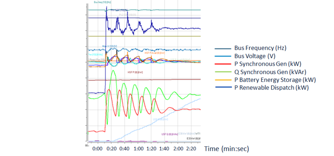
Figure 1 - Denham Site Testing
The plot shows insufficiently damped frequency oscillations caused by instability between the synchronous machines and the battery energy storage system. In some cases, undamped oscillations were observed in the testing for high step loads. A significant contributing factor to this is the relative size mismatch between the synchronous units (each 300kW) and the battery energy storage system (1,500kW), noting that the synchronous units are trying to achieve isochronous control. An additional consideration is the performance of secondary control functions and coordination with primary response functions. Whilst these problems have been resolved, the resolution involves limitations on step load capability and the requirement for a minimum number of synchronous machines to be online.
Limitations associated with traditional methods include poorer step load performance, reduced reliability, reduced renewable utilisation and higher curtailment of DER and centralised renewables.
2. Emerging Microgrid Frequency Control Approach
The new frequency control approach requires all generating units connected to the microgrid to operate in a primary frequency droop mode, with a secondary isochronous response provided by a microgrid controller. This is shown in the following figure, which compares traditional microgrid frequency control approaches with the new approach.
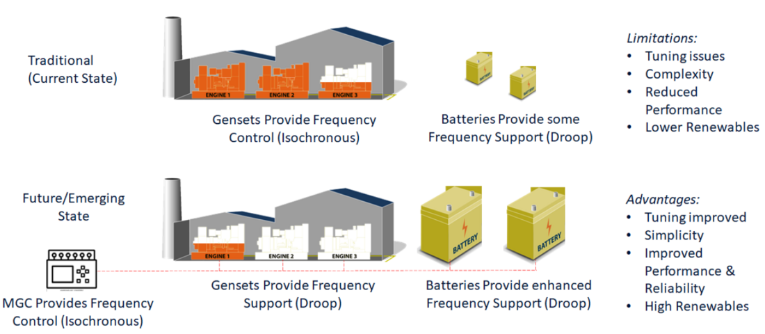
Figure 2 - Microgrid Frequency Control Approach
The primary frequency droop approach sees the primary frequency control function shared across synchronous generators (rotating machines), battery energy storage systems (with battery energy storage systems operating in a grid-forming droop mode at all times), and other renewable and inverter-based generation (also operating in a droop mode where possible).
The primary droop responses are configurable and tuned to ensure a suitable response to microgrid step load and other events. Typically, the droop responses are tuned such that a lesser response is seen from the synchronous machines and PV inverters, and a more significant response is seen from the larger utility battery energy storage systems (operating in grid-forming droop mode). However, a meaningful response to system events is expected from each generating unit in the microgrid, in proportion to its step load capability. Generators are tuned when commissioned to confirm appropriate response to step load (or generator trip) events.
The synchronous generators, operating in a frequency droop mode (or base load if droop is not available), therefore no longer dictate the microgrid frequency. Dispatch commands are written to online generating unit(s) by the microgrid controller (or other means depending on the specific field implementation), depending on load requirements and considering dispatch priorities and generating unit constraints.
Isochronous frequency control is managed by the microgrid controller, which steadily restores 50Hz operation after system events and load fluctuations. This is a secondary control scheme designed to operate relatively slowly and after primary control schemes have operated to manage system events and fluctuations.
This mode of operation requires the microgrid controller to manage dispatch priorities and dispatch generating units on the microgrid (including the gensets) to meet load requirements.
Other key components of the frequency control strategy include:
- All microgrid controller commands have configurable ramp rates and control parameters to ensure stability and suitable damping of oscillations.
- When generating units reach their limits (e.g. when generators reach their minimum load limits) the microgrid controller limits further secondary frequency response commands, and allows the frequency to drift. i.e. The isochronous controller in the microgrid controller does not force restoration to 50Hz if generating units are at limits – in this case the frequency may drift, allowing an additional frequency response from network-connected DER.
- Underfrequency load-shedding of distribution feeder circuits is in place. Underfrequency load-shedding schemes are configurable and typically operate in stages.
- Upon loss of the microgrid controller, or significant grid forming capacity, the control system has the ability to fall back to traditional control methods (i.e. synchronous generators in isochronous control).
The frequency control strategy for various ‘bands’ of frequency operation is shown in Table 1.
| Frequency Response Zone | Frequency Range | Description |
|---|---|---|
| Normal Zone | 49-51 Hz | The primary (inertial and droop) response of all generating units maintains transient frequency performance for small disturbances and load changes. |
| Isochronous control by the microgrid controller dispatches active power of nominated generating units to maintain steady state frequency. | ||
| Response Zone | 47-49 Hz 51-53 Hz | The primary (inertial and droop) response of all generating units maintains transient frequency performance for large disturbances and load changes. |
| Isochronous control by the microgrid controller dispatches active power nominated generating units to restore steady-state frequency. Isochronous control is limited when generating units reach limits to allow frequency drift and a further response from DER. The control system must be able to operate without the microgrid controller in service, utilising the primary droop response of generating units to stay within the 47-53Hz zone for extended periods of time. | ||
| Recovery Zone | <47 Hz >53 Hz | System recovery with under-frequency load-shedding schemes (UFLS). |
| Primary and secondary response schemes continue to operate. |
Note that wider than usual band of microgrid frequency operation allows for increased participation from primary controllers across the microgrid, effectively using the grid frequency as a communication signal, and broadcasting the required supply/demand balance across the microgrid. This shares the burden of primary response across generating units across the microgrid and lessens the reliance on secondary controllers and communications schemes.
In many respects, operation in this manner is similar to the control approach presently adopted by Horizon Power when operating in ‘hydrocarbons-off’ mode, i.e. without any synchronous generating units connected.
3. System Modelling – Yalgoo
System modelling of the new frequency control approach has been completed for Yalgoo, a small remote microgrid in regional Western Australia [3]. The Yalgoo microgrid has three 240kW diesel generating units, two 194 kVA grid forming battery energy storage systems, and a 200kW solar farm, servicing an average load of approximately 120kW.
The studies were completed to test the stability and performance of a range of load scenarios, contingencies, operating mode combinations and primary droop % settings. The following figure shows the result of a trip of the solar farm and one battery energy storage system (connected via the same circuit breaker) for a range of droop % settings.
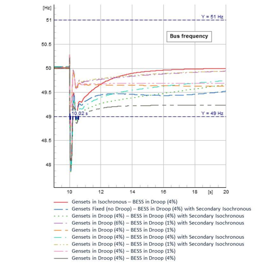
Figure 3 - Yalgoo Modelling Results – Solar Farm & Battery Energy Storage System Incomer Trip
The results show:
- Frequency is within limits for this event, and a stable response can be achieved under all proposed droop settings, showing that operation under frequency droop with wider frequency bands is possible.
- Operation of battery energy storage systems with a relatively tight droop and synchronous generating units in droop or fixed real power dispatch can provide excellent stability performance, alleviate synchronous machine overloads and step changes, and provide increased microgrid step load capability. However, the potential for increased micro cycling of battery energy storage systems with tight droop should be considered in determining droop settings.
- The selection of control modes and droop settings has a large impact on frequency behaviour, stability performance, and relative load distribution during and post-event. The relative load distribution between the synchronous generating units and the battery energy storage systems immediately after a contingency event is a direct function of their relative primary frequency droop settings.
- Secondary controller dynamics are important in governing the post-event load distribution between generating units, and speed at which load distribution and microgrid frequency is returned to normal. Secondary controllers should be designed not to interfere or counteract the dynamics of the primary controllers.
- A suitable primary response on grid following inverters and DER is essential to ensure microgrid frequency stability.
- In microgrids with synchronous generators without droop (operating in fixed real power dispatch), it is important that for loss of grid forming battery energy storage system capability the synchronous machines switch back to isochronous control promptly.
4. Test Case – Denham Factory Tests
Factory tests have been completed for the Denham Power microgrid to test the performance of the new frequency control approach.
The tests were performed in the factory, with scaled-down equipment to approximately represent the equipment in the field including a 48kW genset to represent the 320kW genset, 97kW battery energy storage system representing the 1.5MW battery energy storage system in the field, 200kW load bank and 60kW PV system.
The plot in Figure 4 shows the frequency response to a 75kW step load (this step load was chosen to be representative of the 400kW step load conducted in the field as shown in Figure 2, but scaled down to the size of the factory test equipment).
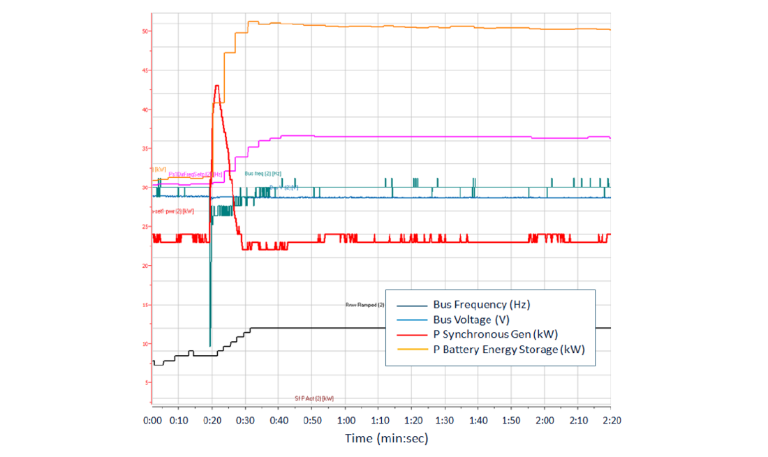
Figure 4 - Denham Factory Testing
The plot shows a stable and well-damped response to step load events, in contrast to Figure 2 which shows oscillations between the battery energy storage system and synchronous generators.
The plot demonstrates the benefits of moving the dominant primary frequency response from the synchronous machines to inverter-based generation in situations where the inverter-based generation begins to dominate the microgrid (in this case from the synchronous reciprocating machines to the grid forming battery energy storage system). If traditional methods were employed an overload on the genset would have been seen along with conflicting control between the genset trying to perform isochronous frequency control and the grid-forming battery energy storage system responding in a primary droop.
5. Test Case – Carnarvon Gibson Microgrid Trial
A key component of the new frequency approach is reliance on system frequency droop to handle the initial frequency response to system events. The microgrid controller provides the microgrid isochronous control once the primary controllers have had a chance to operate (commencing after approximately 5 seconds).
Testing has been conducted on the Carnarvon Gibson Microgrid [1] to assess microgrid performance in the absence of a microgrid controller performing the isochronous function.
The Carnarvon Gibson Microgrid is a low-voltage microgrid in the West Australian town of Carnarvon, located approximately 900 km north of the city of Perth. It is connected to the main Carnarvon network via a pole top 315 kVA, 22 kV / 415 V transformer. The microgrid has approximately 40 customers, with a peak load of 130 kW. There is a total of 157 kW of behind-the-meter PV installed, and approximately 30 kW of behind-the-meter battery installations.
A 100 kVA / 50 kWh utility-grade battery energy storage system has been installed on the network to allow the microgrid to operate in islanded mode, disconnected from the main grid. The purpose of the microgrid is to run technical trials and test DER control techniques in a low-voltage network with a high level of DER.
The following plot shows the microgrid's performance operating with a droop response only (frequency droop of 4%) for approximately one hour and thirty minutes, with no isochronous control active.
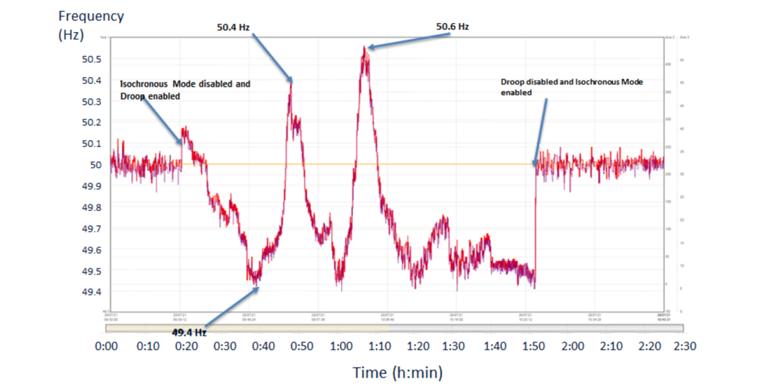
Figure 5 - Carnarvon Gibson Microgrid Frequency Droop
The plot shows that the microgrid stayed within the normal frequency operating range of ±1Hz for the 1.5-hour period for normal load and DER fluctuations. The two main frequency variations were due to two passing clouds on the microgrid.
The plot shows the ability to operate on primary response for a period of time, supporting the strategy of a delayed response from the isochronous controller. In fact, consideration could be given to extending the time of operation on primary response only, and occupying a wider frequency band, like the method employed at National Renewable Energy Laboratories (NREL) Flatirons Campus microgrid [2].
Another component of the frequency control strategy is the broad involvement of DER and network-connected generation in supporting system frequency. Additional testing on the Carnarvon Gibson Microgrid has focussed on the performance and response of customer DER systems to frequency fluctuations, particularly the Hz-watt primary response of DER to support the microgrid.
The following plot shows the inverter (DER) response to frequency variations on the microgrid. In this plot the frequency was increased from 50 Hz to 53 Hz and then back to 50 Hz over a half-hour period, noting the response of the DER to the frequency changes.
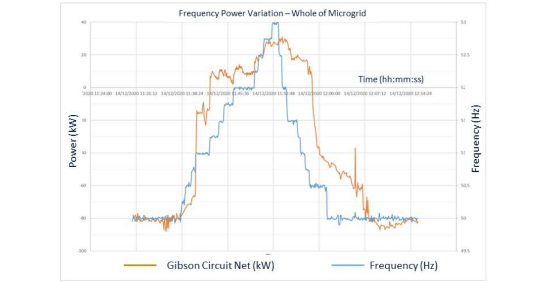
Figure 6 - Carnarvon Microgrid Inverter Droop Response
The plot in Figure 6 shows the nett load and frequency on the Carnarvon microgrid during the test. The plot shows that as the frequency increases, there is a reduction in DER output, causing an increase in the nett load on the microgrid. It can be noted that this response is not uniform due to the varying age, nature of the DER, and compliance with standards [4].
The DER response, whilst highly variable depending on the nature and compliance of individual DER systems, shows an overall primary droop response which assists in the management of system frequency.
A key component of the overall frequency control strategy is one which allows a broader frequency operating range and hence allows for the involvement of DER and network-connected inverter-based generation in supporting system frequency response.
6. Site Deployments
This control approach (or very similar approaches with various microgrid-specific modifications) has been deployed at several microgrids including:
- Horizon Power – Sandstone, Wiluna, Yalgoo, Kalumburu (when in hydrocarbons-off mode), and Marble Bar (when in hydrocarbons-off mode)
- Pacific Energy – Multiple isolated mine power systems throughout West Australia supporting Hydrocarbon Off Operation, with peak load demands up to 15MW.
- National Renewable Energy Laboratories (NREL) Flatirons Campus, Colorado, USA [2]
It is important to note that whilst the underlying principle of frequency control is common across these approaches, the specific implementations vary in terms of the utilisation of cascaded droop schemes as well as fossil fuel resource coordination.
7. Discussion
The studies, testing and in-field performance, has highlighted the validity and improved performance of the new frequency control strategy. The new frequency control approach relies on the primary frequency response of all generating units on the system (including inverter-based generating units) and suitable layering of primary and secondary control schemes. This allows for a simple and robust control philosophy.
Careful planning and determination of primary droop settings is required, with consideration of the relative ratio of droop settings between generating units to ensure good sharing of response to system events. It is noted the ration of droop settings between generating units determines the frequency behaviour and distribution of step load following contingency events.
The utilisation of the primary frequency control allows for the removal of multiple secondary functions deployed in traditional power station and microgrid controllers. The frequency control approach allows the removal of multiple control modes for certain generating units and reduces the reliance on communications systems (or in some cases allows removal of the requirement for communications systems as in the NREL Flatirons Campus microgrid [2]).
The frequency control strategy has a number of benefits including improved stability, improved step load capability and response to load and renewable fluctuations, improved redundancy, improved contribution to system events across all generating units, simplification of operating states and hydrocarbons-on to hydrocarbons-off transitions, reduction in the criticality of secondary control functions and associated reliance on the microgrid controller, stable genset load control, good management of low loading and potential reverse power events, and minimisation of curtailment of renewable energy generating units.
8. Recommendations and Future Work
It is recommended system analysis be conducted for each microgrid to determine suitability of this control philosophy and recommended settings for implementation. System tuning is required for grid-forming inverters to achieve stability and to achieve a suitable balance of primary response across gensets, battery energy storage systems and DER. Further the following should be considered:
- Regulations be updated for a wider frequency operating range.
- Standards (e.g. AS4777) be amended to cater for a wider frequency operating range and ongoing ride-through and frequency support from DER. Droop responses about an operating point may be preferable to fixed numerical values.
- Consideration be given to alternative approaches for maintaining clock time in microgrids.
- Review of UFLS schemes, settings, and Pre-emptive Load-Shedding (PELS) schemes.
- DERMS optimisation to reduce curtailment impacts.
- Consideration of micro-cycling effects on battery life and performance.
References
- D. Edwards, “Carnarvon Distribute Energy Resource (DER) Trials Technical Report #2”, Horizon Power, Murdoch University, 2021.
- P. Koralewicz, E. Mendiola, R. Wallen, V. Gevorgian, D. Laird, “Unleashing the Frequency: Multi Megawatt Demonstration of 100% Renewable Power Systems with Decentralized Communication-Less Control Scheme”, National Renewable Energy Laboratory, Technical Report NREL/TP-5000-80742, 2022.
- S. Cherevatskiy, “Review Of Shared Power Station Frequency Droop Control Strategy - Case Study Yalgoo Microgrid”, Enerjia, 2023.
- D. Stephens, R. Brown, S. Elphick, “A Practical Method for Control of PV Generation in Microgrids”, CIGRE 2022 Kyoto Symposium, Paper number C000151, Japan, 2022.