Design Decisions of Process Bus Technology for a Distribution Utility
Authors
R. ROBINSON, B. ARMSTRONG, K. MALVERN - Endeavour Energy

Summary
Sydney, Australia is the 10th most expensive city in the world and is undergoing significant growth whilst transitioning to renewable energy sources. Innovative design principles were required to re-engineer the next generation of substations to provide a sustainable and efficient design delivery whilst maintaining a safe and reliable network.
The rollout of IEC 61850 digital substations has gained momentum and popularity over the past two decades, with most protection engineers across the globe having exposure to some degree of digital substation with mixed emotions towards the transition. A small team embarked on a journey of discovery to map out the pathway to implementing simplified and successful modern digital substations to increase our organisations agility and efficiency to defer investment, reduce capital expenditure, project timelines and operational maintenance costs.
This paper provides insight to the comprehensive research and development carried out and some of the design decisions which have been successfully implemented in several substations focusing on providing clarity to field technicians and protection engineering teams to demystify IEC 61850 substations. Previous experiences with Generic Object Orientated System Event (GOOSE) and Manufacturing Message Specification (MMS) provided a strong foundation for the successful transition to process bus.
Savings of approximately 22% in capital expenditure and 58% protection system operational costs are realised with the modernised digital substation design philosophy adopted here when compared to a conventional secondary system and brick-and-mortar build.
Keywords
Process Bus, Station Bus, Digital Substation, IEC 61850, Sampled Values, GOOSE, Innovation, Virtual Isolations1. Modernising substations with digital technology - Operating context
Sydney, Australia is the most populous city in Oceania, is currently undergoing significant growth and redevelopment to form a metropolis of three cities aligning land use, transport, and infrastructure to reshape Greater Sydney as three unique but connected sites.
Many of the areas undergoing significant change in Greater Sydney have minimal electrical infrastructure, originally designed to support regional communities. A number of utility owned zone substations primarily connected to the 132kV transmission network and supplying the 22kV distribution network have been planned to accommodate the growth areas as well as a significant increase in customer funded substations and switching stations to enable the connection of large-scale renewable energy generation, battery energy storage systems (BESS) and data centres. The rapid growth coupled with high land and development costs in the 10th most expensive city in the world [1] called for a refreshed approach to the engineering, procurement, and construction (EPC) of substations.
2. Prior Experience with IEC 61850
In 2013 a 33/11kV zone substation with a firm rating of 35MVA utilising IEC 61850 station bus including GOOSE based tripping was constructed as a turnkey substation with the major design components outsourced. Although the project was an engineering success, an unfamiliar design and lack of project documentation led to hesitation of secondary system augmentation. This project highlighted the importance of implementing systems that the organisation could easily transition to.
Since 2016 MMS has been widely adopted by our organisation as the preferred SCADA interface from intelligent electronic device (IEDs) to substation remote terminal units (RTUs). This increased our overall exposure to the IEC 61850 data model with many lessons learnt in the initial design of these MMS reports.
Given almost a decade had passed since the first and only implementation of GOOSE based tripping the organisation decided to explore digital substations once again to expedite construction whilst reducing overall costs, this time to implement full process bus technology. The drive for increased agility and ability to maximise the infrastructures capabilities allowing an efficient response to the rapidly changing operating environment was at the forefront of the project team members minds and remained the core focus throughout the project.
As a result, the project team kept all expertise in house and designed a system that kept operational stakeholders at the forefront of all major design decisions without compromising the benefits of using process bus. The following sections provide context to the various project stages which provided opportunities to reflect on findings and realign the projects strategy towards the end goal as required.
3. Conventional Substation Processes and Timelines
Prior to the adoption of changes detailed in this paper, the timeline to establish a conventional substation was a little over three-years from the final business case approval and commencement of detailed design (Figure 1). The civil build was identified as an extensive and expensive component of the project scope with a ‘brick-and-mortar’ build forming a major milestone on the projects critical path. The Mechanical and Electrical (M&E) fit out carried out by internal teams could not proceed until the site had been handed over from the building contractor.
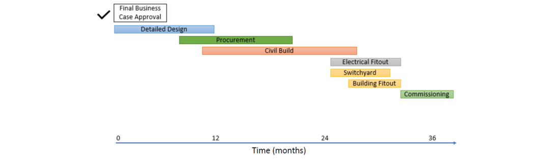
Figure 1 - Conventional substation project timeline
Various internal design teams collaborate to determine the design of each substation whilst developing the business case to determine high-level details such as indoor or outdoor substation, number of and rating of power transformers and both incoming and outgoing circuits to establish the project budget and timeline.
The detailed secondary systems design commences with the protection design team providing a conceptual design which serves as a design input to the electrical design. The conceptual designs are typically templated to provide solutions for each bay type utilising protection IEDs and SCADA equipment on our period contracts, ensuring that each generation of substation provides consistency for engineering and field work parties.
The electrical design team interpret the conceptual design to produce an I/O list for the SCADA team and an array of schematics, cable schedules and safety in design documentation. The design outputs undergo a review and approval quality control process prior to being released for the site procurement and construction.
4. Digital Substation Secondary System Design Process Integration
A review of the substation design process by the substation modernisation project teams highlighted opportunities for significant savings to project cost and timelines. To achieve the required project outcomes the following changes were determined as high priority and focus areas,
- Modular prefabricated buildings constructed offsite - providing the ability to carry out concurrent civil construction and M&E fit out
- Air Insulated Switchgear (AIS) rather than GIS - reducing cost and improving environmental sustainability
- Digital substation technology - providing compact control room layout, significant reduction in copper cabling and associated ducts and trenching
The theoretical timeline for future 132kV outdoor substation construction is shown in Figure 2 with a reduction from 36+ months to less than 24 months when compared to a conventional substation. Standardisation of the modular design provides the ability to have much of the detailed design completed ahead of the formal project kick-off.
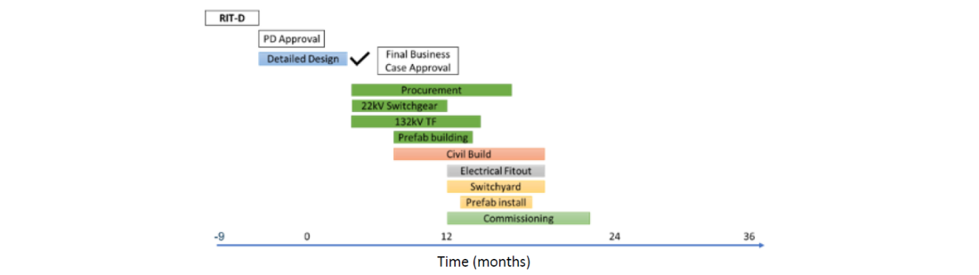
Figure 2 - Digital substation project timeline
The outcomes of the substation modernisation project were piloted with the establishment of South Erskine Park Zone Substation located in Western Sydney powering a large commercial and industrial precinct. The substation initially consisted of two 132kV incoming feeders, three sections of 132kV busbar, two 132/22kV 45MVA power transformers, two sections of 22kV and utilised prefabricated buildings to house the protection and control equipment, amenities block as well as each section of 22kV switchgear. The surrounding area underwent unprecedented growth and weeks prior to the initial energisation approval was granted to add a third power transformer and accompanying section of 22kV switchgear providing ample opportunity to showcase the agility of a digital substation undergoing augmentation.
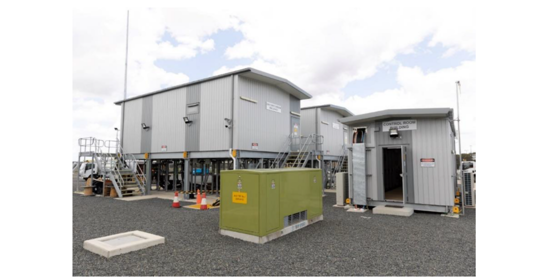
Figure 3 - Prefabricated substation buildings
Utilising prefabricated buildings provided several benefits such as significantly reduced civil work and allowed project deliverables to be carried out in parallel. Installing the 22kV switch rooms on steelwork negates the requirement of a basement construction and the open design also provides a safer work environment for cable installation and jointing crews with adequate fresh air and means of entry and egress.
5. Research and Development Phase
5.1. Market Engagement
The project team formalised a market engagement requesting vendors to provide process bus equipment to carry out testing and finalise the development strategy. Working with multiple vendors who were at various stages of their product development roadmaps provided the initial knowledge of engineering processes, message formats, manufacturer implementation techniques and individual testing requirements.
A simple testing laboratory was established within our office consisting of two 19" protection panels where equipment from a large selection of suppliers was installed and tested as shown in Figure 4.
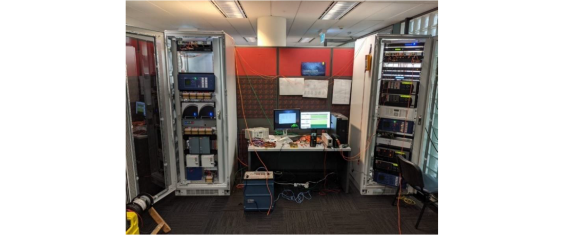
Figure 4 - Initial R&D lab
Initial tests included GOOSE and SMV mapping, test and simulation mode behaviour, time synchronisation, SmpSynch behaviour, and playing out various maintenance and augmentation scenarios to ensure the optimum solution was achieved. This exercise provided an excellent opportunity to influence the development of several vendors’ products and gain a thorough understanding of the IEC 61850 standard.
5.2. System Engineering
Using a substation configuration description (SCD) file and a top-down engineering approach was explored in the early phases of the project. Although we discovered the SCD file had many benefits, they were more pronounced for a turnkey substation solution. As our organisation is set up to develop, design, commission and maintain substations we found designing a solution with templated messages would capture the majority of digital substation benefits and minimise the impact to existing processes and ease the digital transition.
5.3. End User Engagement
A combination of online meetings with utilities from across the globe and site visits to Australian utilities were carried out to gain a deeper understanding of trends in the industry. The utilities were chosen based on their experience with IEC 61850 substations, many of whom were either in a similar position to us with the commencement of a detailed research and development (R&D) phase or were in the process of actively designing and commissioning process bus substations.
The main topics workshopped were time synchronisation, redundancy of systems, and engineering processes related to the testing, maintenance and fault finding of process bus systems. The meetings provided a forum to discuss issues found with vendor implementations and to gain an understanding of gaps in the standard which allow vendors to interpret implementations.
5.4. In-Service Pilot Testing
A substation which utilises conventional protection circuits and had sufficient spare CT cores available was selected for an in-service trial whereby process interface units (PIUs) from five different manufacturers were installed to an array of IEDs from three different manufacturers alongside in-service conventional protection schemes. The process bus IEDs were not capable of tripping circuit breakers to ensure network reliability was not compromised. A range of products of this size were selected to test engineering processes and verify stability within multi-vendor arrangements. Analysis of network fault response was carried out by manual COMTRADE analysis after faults occurred and various non-intrusive techniques such as a network traffic analysis.
6. Detailed Design Phase
The overarching design intent for the project team was to introduce IEC 61850 process and station bus equipment to remove the copper interface from primary equipment to the protection and control room and digitise all data close to the source. This was to take place whilst having minimal impact to existing design processes ensuring efficient outcomes in back-office operations as well as the site commissioning, maintenance and fault-finding activities.
The project team designed and built a full-scale replica substation secondary system as shown in Figure 5. This served to showcase design decisions and functionality to stakeholders within the business and gave the project team valuable feedback which could be incorporated back into the design.
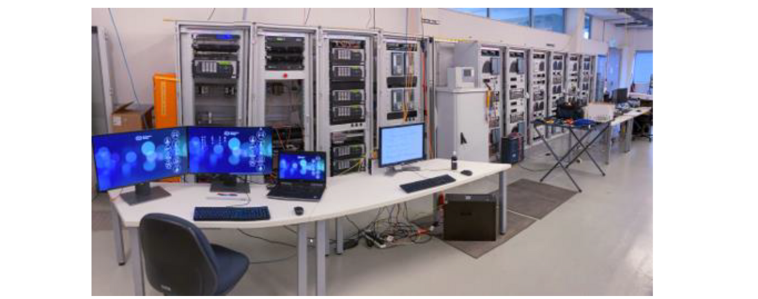
Figure 5 - Full scale proof of concept
6.1. Protection and Control Equipment Layout
Conventional substation designs would typically see a number one system installed in the top half of a panel and the number two system installed in the bottom half. A compact protection panel design (Figure 6) which groups the number one protection and number two protection equipment into separate panels to minimise control room footprint was implemented, our digital substation design allows multiple protection schemes to be installed in a single panel with isolation links only existing in the PIU cubicle.
The compact design allows the installation of the following IED’s in a 600x600mm footprint.
- 3 x 132kV line protection IEDs
- 3 x 132/22kV transformer protection IEDs
- 3 x 132kV low impedance BBP IEDs
The previous conventional substation design would have required a total of eleven panels, the compact design offers significant savings in land requirements, construction time, costs, transport, and air conditioning requirements for prefabricated buildings.
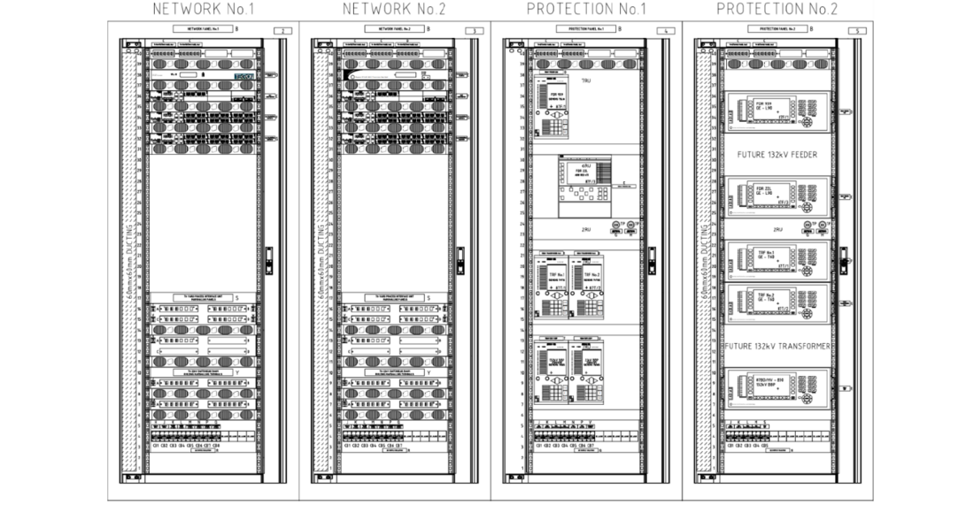
Figure 6 - Compact Panel Design
The PIU cubicle provides the interface between conventional substation wiring and the digital substation, Figure 7 shows the DC and AC circuit isolations for a 132kV bus section CB. The black links identify CT circuits and grey links are DC circuits. A station bus test port is installed to allow engineering access to IEDs and SCADA systems while performing PIU checks.
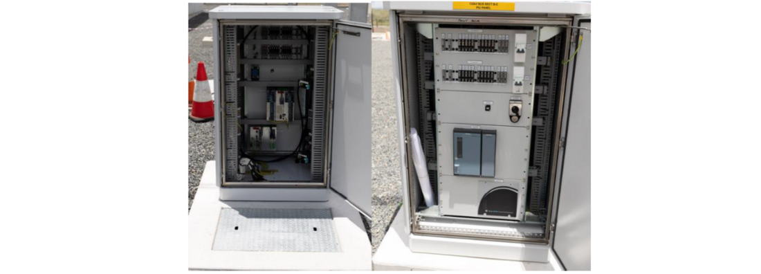
Figure 7 - PIU cubicle rear and front view
6.2. Configuration Standardisation and Templates
Standardisation and templating were the key to success, with up to twenty substations in the pipeline over the next ten years a solution which was repeatable and consistent for internal teams was critical, keeping in mind the primary configuration would likely change for each substation.
The first step was to replace copper wires with individual GOOSE messages to draw comparisons of conventional and digital substations, which in turn ease design, commissioning, and fault-finding activities. Categorisation of bay types was carried out with the following secondary systems designs required;
| • HV Feeder Bay | • Busbar Bay | • Transformer Bay |
| • Bus Section Bay | • MV Feeder Bay | • Station Level |
IEDs were selected for each of the bay types, separation and duplication of the secondary systems was achieved with separate process bus networks and all electronic equipment such as network switches, protection IEDs and PIUs being of different make and manufacturer eliminating a common mode of failure. Standardised GOOSE and sampled measured values (SMV) datasets were configured for each of the IEDs in setting file templates used by our design teams to instantiate bays within each substation, hence overcoming any engineering issues relating to primary configuration changes. The templates also provide an agile approach to substation augments by adding placeholders in the GOOSE datasets that can be utilised in future projects without breaking in-service configurations.
The templated designs require minimal changes by our designers, this allows the IEC 61850 settings to be treated like protection setting parameters which are modified on a per bay basis. Table 1 displays the IEC 61850 settings required to be modified for each IED as it is instantiated:
| IED | GOOSE | SMV |
|---|---|---|
| IED Name | GOOSE ID | SMV ID |
| IP Address | Destination MAC Address | Destination MAC Address |
| VLAN ID | VLAN ID |
A network spreadsheet (Figure 8) was created as a simple means to display and verify where each of the messages are sent and received and replaces a traditional cable schedule and electrical connection diagram. A Python script was developed that uses the network spreadsheet to produce configuration files for both process bus switch models and supporting network documentation.
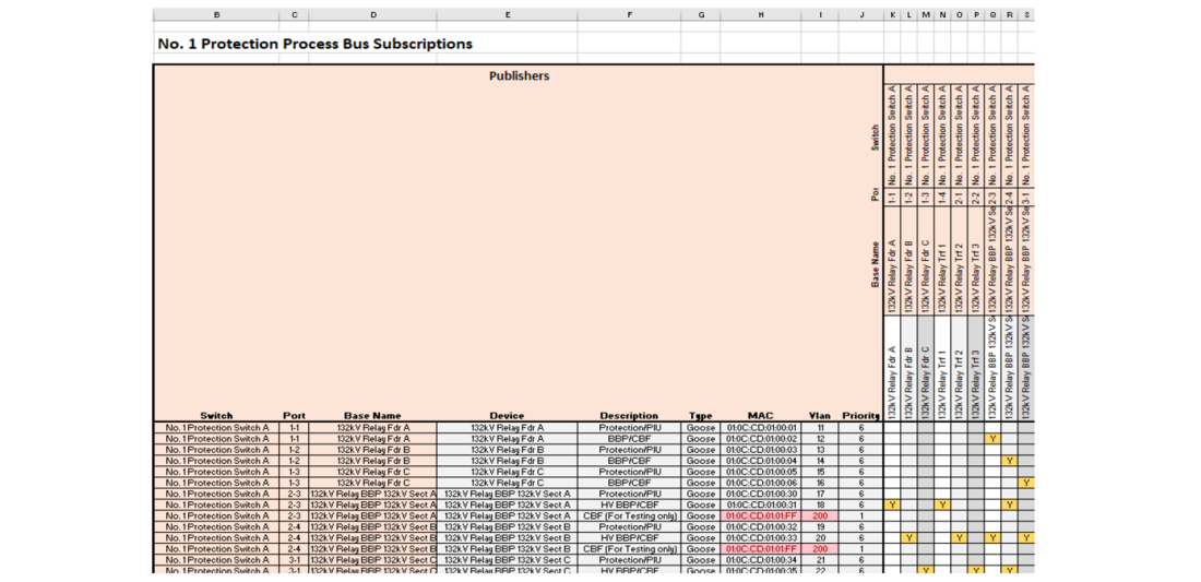
Figure 8 - Process bus network spreadsheet showing GOOSE mapping
All messages within the design are of a one-to-one relationship with the exception of low impedance BBP GOOSE trips. This configuration overcomes the issue that we faced at our first GOOSE based tripping substation whereby a secondary system augmentation can result in undesirable consequences due to one-to-many or many-to-one relationships.
Digital signals are separated into applications in the same manner that a conventional substation would separate functions into multicore cables. This is represented on the protection settings document in a way that represents a conventional copper wiring connection diagram as shown in Figure 9. Creating the system in a manner that was familiar to operational stakeholders was a key learning from previous projects.
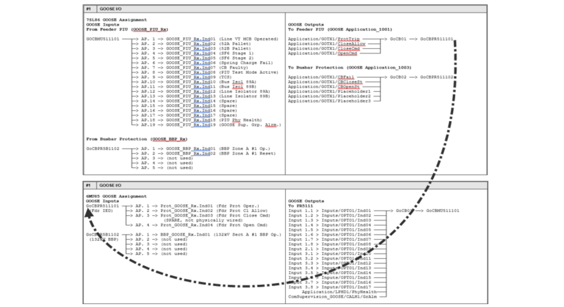
Figure 9 - Protection settings documents showing GOOSE input and output from protection IED (top) to PIU (Bottom)
Each of the GOOSE and SMV messages are configured with their own unique VLAN to allow for enhanced traffic management, the design template ensures that every IED has a unique IED name, VLAN, MAC address, GOOSE ID and SMV ID as required. The exception to this is the test VLANs which don’t have destination IEDs, as they are only used for protection testing, they are identical.
6.3. Process Bus Network Design
The process bus network design is considered a vital component of each protection scheme. Following the same design principles as our protection IEDs physical and virtual separation and the use of a separate make and model for each electronic device mitigates the risk of a single failure mode. Parallel Redundancy Protocol (PRP) was not justified for our application as we have dedicated and physically separate process bus networks for both protection schemes and a short response time for field staff to rectify network faults. As a result, we were able to conserve control room space, reduce the number of fibre optic cables and complexity for the digital substation transition.
A Rapid Spanning Tree Protocol (RSTP) backbone is provided to connect all process bus switches within each system. The RSTP backbone is not intended to provide full redundancy of each network, but it was decided upon to overcome likely single failures between switches such as patch lead, SFP or port failure. This backbone connection also provides a means for all VLANs to ingress and egress to each switch which simplifies testing and configuration.
To utilise SMV and GOOSE in a digital substation precision time synchronisation is critical, we have designed each of our process bus networks to consist of both a GNSS grandmaster (GM) clock and a non-GNSS GM clock which will become the GM clock only in the event of a GNSS GM failure. Our design ensures that our substation remains operational and stable if the GNSS clock is damaged or taken out of service, our protection schemes can run on SmpSynch of 1 indefinitely.
6.3.1. Typical Topology
All ports on the Process Bus network are fibre. The typical process bus network (Figure 10) consists of a core switch which connects the following equipment,
- 1x GNSS clock
- 1x non-GNSS clock
- 1x 1Gbps link to first Protection Switch (RSTP Backbone)
- 1x 1Gbps link to the last Protection Switch (RSTP Backbone)
- Test Ports for protection testing
- Mirror port for non-intrusive fault finding
The number of protection switches is dependent upon the number of IEDs within the substation. Each switch has a unique configuration file automatically generated by the previously discussed Python script. Switches are connected to substation IEDs in descending voltage and primary topology. Each of the switches follow the connections as below,
- 1x 1Gbps link to upstream switch
- 1x 1Gbps link to the downstream switch (or back to the Core Switch)
- Mirror port for non-intrusive fault finding
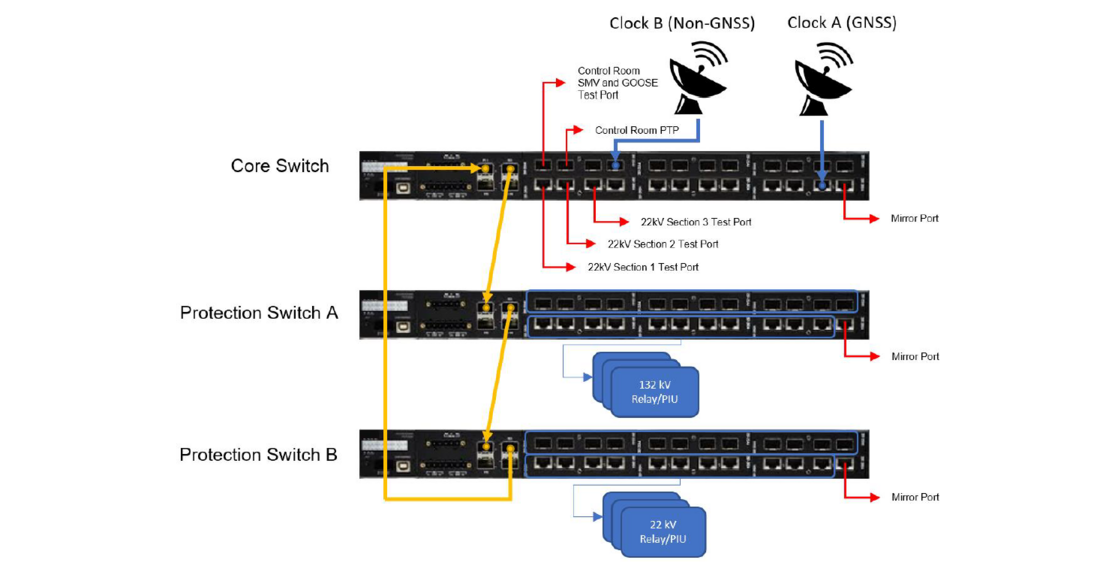
Figure 10 - Three-switch process bus network topology
6.3.2. Test and engineering ports
To mitigate technician error when protection testing, dedicated testing ports were installed at strategic locations and permanently patched into process bus switches. The functionality of these testing ports is dependent on the type of testing required at each location and are considered when designing the network.
Within the main protection and control room our technicians are required to complete full digital testing of the protection IEDs as there are no electrical injection points. To accommodate this testing there are two test ports, the precision time protocol (PTP) test port allows only PTP messages to ingress and egress and is used to time synchronise the protection test set to the process bus network. The second port is for GOOSE/SMV testing, which allows all GOOSE messages to ingress and egress the network and SMV to ingress the network only as required for IED testing. The 22kV switch rooms have dedicated test ports within, which allows all GOOSE messages to both ingress and egress the network. There are no SMV ingress capabilities within these rooms as AC injection links exist.
Use of these test ports allow for commissioning, maintenance and fault finding to be carried out with permanently patched connections and negates the need for technicians to interact directly with the process bus network switches during maintenance or setting change tasks. Having these design inputs for each of the testing port has allowed us to test all aspects of the protection scheme and is still within the bandwidth capabilities of the protection test set.
The final port on each of our switches is configured as a mirror port and by default has no traffic mirrored to it, technicians have been provided with appropriate training and documentation to configure the port arrangement to carry out non-intrusive fault finding akin to the use of a digital multimeter on an in-service conventional substation circuit.
6.4. Enhanced SCADA control capabilities
Standard work practices within our organisation call for protection scheme isolations known as protection mandatory isolations (PMIs) under certain primary isolations, one such example is bus bar differential current transformers (CTs) connected to high impedance BBP schemes when operational earths are applied and provide a path for current to flow if a fault occurs elsewhere on the network.
A typical PMI requires a worker to isolate secondary circuit links as listed on a predetermined isolation sheet, there is risk involved with the isolation and restoration of these links which could constitute an inadvertent trip or electric shock if open circuiting the incorrect CT links. MMS controls are now configured within the substation RTU which provide virtual PMIs. The controls virtually isolate differential CT’s and blocks GOOSE CBF trips, which has eliminated the need for technicians to interact with AC or DC links. Interlocks are configured to prevent PMIs being applied prior to primary isolation and block the primary restoration whilst a PMI exists. The implementation of IEC 61850 by each vendor differs slightly and as a result test mode could not be used to provide a consistent PMI approach without causing nuisance alarms to our SCADA system and consequently system operators. Test mode and simulation mode are used solely by Protection and Control technicians for testing purposes or to isolate entire schemes.
Open and close controls from the SCADA system to circuit breakers within our conventional substations are via a single trip coil and bypass the protection IED. The digital substation design incorporates SCADA controls via both number one and two trip circuits and traverse an identical virtual circuit as protection trip signals. The intent behind this design philosophy is to provide a means of carrying out online maintenance where both trip circuits can be tested via remote trip and close commands.
7. Process Bus Key Learnings
The project team were confident in the configuration and testing of conventional protection schemes utilising numeric IEDs and copper wiring and were also convinced that for the best part our existing processes did not require significant change however they did identify that significant development work was required to gain confidence and competence in process bus network testing.
7.1. Process Bus Network Testing
Security and stability of the process bus network is paramount, a common finding throughout the project R&D phase was that upskilling technicians to be competent at network analytics is a challenge. To provide a solution to these problems and requirements a handheld network tester (Figure 11a) was utilised which is comparable to a technician’s digital multimeter which was easy to use and cost effective. The project team collaborated with the manufacturer to develop an all-in-one solution which negates the need for technicians to connect laptops to networks or carry out intrusive work to fault find.
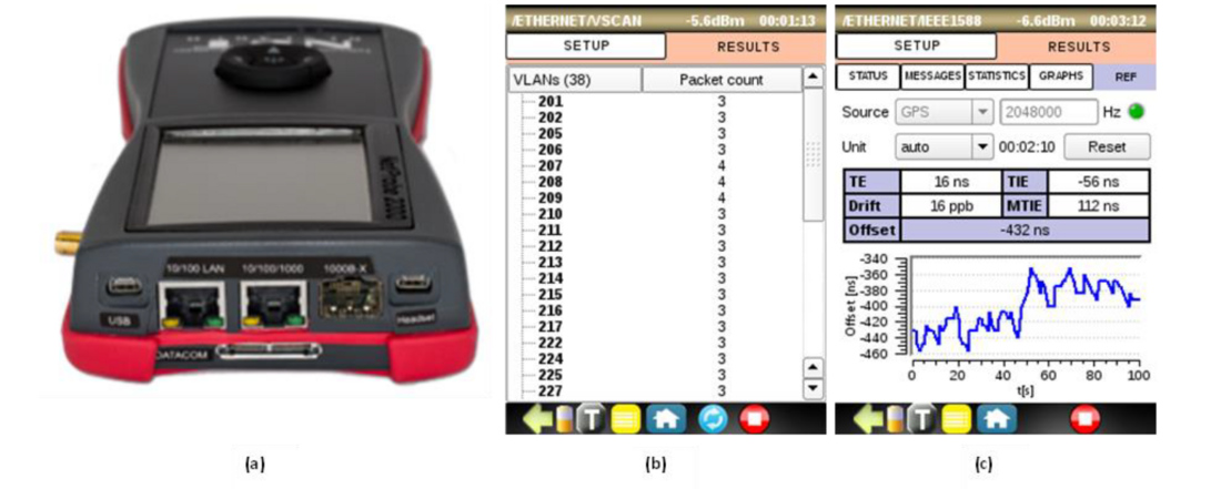
Figure 11 - (a) Handheld network tester (b) VLAN validation (c) PTP validation
Factory Acceptance Testing (FAT) of the process bus network switch configuration requires confirmation of the VLAN configuration to the design intent. Technicians carry out testing by simply connecting one port of the network tester to the mirror port of the process bus switch and the other network tester port to each process bus switch port. Figure 11b shows an example of a singular port where thirteen VLANs are configured, this is a quick and effective means for technicians to verify that the correct network configuration exists, reducing time and effort fault finding during Site Acceptance Testing (SAT).
The network tester is also used to verify the PTP configuration throughout the network by again connecting to the mirror port of each switch for a period of 30 minutes confirming that the offset (Figure 11c) of the PTP synchronisation and GNSS time source does not exceed 1μs. The final switch in the normal network topology is monitored for a period of 6 hours to ensure there is no unexpected behaviour, any abnormalities are expected to be present at the last switch in the chain.
The network tester is also used to verify the PTP configuration throughout the network by again connecting to the mirror port of each switch for a period of 30 minutes confirming that the offset (Figure 11c) of the PTP synchronisation and GNSS time source does not exceed 1μs. The final switch in the normal network topology is monitored for a period of 6 hours to ensure there is no unexpected behaviour, any abnormalities are expected to be present at the last switch in the chain.
7.2. Project Outcomes
Digital substations have proven to be advantageous over conventional substations in terms of construction methods and cost. Unlike conventional substations, digital substations support modular, low-cost, parallel construction methods. They can be constructed offsite and easily delivered to the site after undergoing Factory Acceptance Testing (FAT). On-site requirements are minimal, involving the connection of fibre optic cables and auxiliary power supplies.
The successful implementation of digital substations focused on familiarity, retaining expertise, and maximising the benefits of process bus technology. System design considerations have resulted in scalable solutions that require minimal disruption during maintenance and augmentation activities. The organisation has conducted extensive research and development activities with multiple vendors, benefiting not only themselves but also the global IEC 61850 community.
Process bus technology has improved safety by allowing comprehensive FAT in a controlled environment, eliminating the need to interact with in-service CT or VT links and live 120V DC circuits. It also enables constant monitoring of GOOSE and SMV messages, along with advanced monitoring features like CT supervision, increasing substation reliability by addressing historic issues of broken wires and insulation breakdown.
The organisation's agility in adapting to the evolving energy supply landscape has significantly increased. They can defer infrastructure investment until necessary due to shorter construction and commissioning timelines. This leads to cost savings and the ability to provide safe and reliable electricity to customers more efficiently.
The changes discussed in the paper have resulted in approximately 22% savings in project expenditure at South Erskine Park ZS, with further savings expected as processes mature. Operational costs of secondary systems are also anticipated to reduce by approximately 58% over the 25-year life of a digital substation, thanks to advanced monitoring capabilities.
Future plans for substation modernisation include remote protection IED testing and the exploration of non-conventional instrument transformers to continue the digital transition. Remote testing procedures have already been developed and tested during the COVID-19 pandemic, showcasing the organisation's adaptability. The adoption of non-conventional instrument transformers is expected to bring savings in weight, size, and cost for future switchgear.
References
- World Economic Forum, “These are the most expensive cities in the world,” Centre for the New Economy and Society, 2022.