A1 - Design aspects of synchronous condensers
Authors
Gerfried MAIER, Serdar KADAM - Andritz Hydro, Austria

Summary
This paper discusses several aspects of synchronous condenser design, such as reactances and short circuit contribution, inverse sequence and harmonic current capability, reactive power capability and the difference between salient pole and cylindrical rotor. Indications are given, how these design features are influenced by typical specification parameters and how they influence operation.
Keywords
Synchronous condenser, design, subtransient reactance, reactive power capability, salient poleSymbols & abbreviations
| AC | Alternating current (courant alternatif) |
| AVR | Automatic voltage regulator |
| CR | Cylindrical rotor |
| d | Direct (axis) |
| D | Damper (winding) |
| DC | Direct current (courant continu) |
| f | Field (winding) |
| HV | High voltage |
| LV | Low voltage |
| LVRT | Low voltage ride through |
| M | Torque |
| P | Real power |
| PCC | Point of common coupling |
| p.f. | Power factor (cos(φ)) |
| PV | Photovoltaic |
| p.u. | Per unit (relative units) |
| q | Quadrature (axis) |
| Q | Reactive power |
| RoCoF | Rate of change of frequency |
| SC | Synchronous condenser |
| SCC | Short circuit contribution |
| SP | Salient pole |
| V | Voltage |
| E | Synchronously generated voltage |
| f | Grid frequency |
| H | Stored energy constant |
| If | Field current |
| Im{x} | Imaginary part of x |
| j | Imaginary unit |
| J | Moment of inertia |
| k( | Complex synchronizing number |
| kt | Transformer transfer ratio for the selected tap in p.u. |
| MS,N | Rated apparent torque |
| PS | Synchronizing power |
| Qr | Reaction reactive power |
| r1 | Stator winding resistance |
| rDd | Damper winding resistance, direct axis |
| Re{x} | Real part of x |
| rf | Field winding resistance |
| S | Apparent power |
| SN | Rated apparent power |
| U | Terminal voltage |
| x1 | Stator winding leakage reactance |
| xd | Synchronous reactance, d-axis |
| xd’ | Transient reactance, d-axis |
| xd’’ | Subtransient reactance, d-axis |
| xhd | Main reactance, d-axis |
| xt | Transformer leakage reactance |
| x | Damper winding leakage reactance, d-axis |
| x | Field winding leakage reactance |
| xq | Synchronous reactance, q-axis |
| xq’ | Transient reactance, q-axis |
| xq’’ | Subtransient reactance, q-axis |
| Rotor angle | |
| Angular frequency of the grid (= 2 π f) | |
| Rated angular grid frequency | |
| Swing angular frequency |
Introduction
Power generation with rotating electrical machines provide grid services, which are important to operate a power system. These grid services are short circuit contribution, reactive power provision and inertia. While inertia is not renumerated in most of the countries, due to the abundant availability of synchronous generators, there is a system inertia market in the UK [1].
With increased penetration of the power system with renewable energies which currently provide no or very limited grid services and the phase-out of thermal power plants, demand for grid support continuously increases.
Synchronous condensers (SC) are a proven and reliable technology [2], that can be either deployed as brown field (conversion of existing synchronous generators at power stations) or green field solutions [3].
It is observed, that the demand for synchronous condensers is increasing, to cover the shortfall of inertia, fault level contribution and reactive power in power systems in various regions around the world, to strengthen the grids and to support the integration of photovoltaic (PV) and wind generation [4].
1. Damper Winding & Subtransient Reactances
In order to dampen torsional oscillations, synchronous machines designed for grid operation are typically equipped with features to provide damping. Whilst the most common way is a dedicated damper winding located on the poles, also solid components such as pole tips provide damping.
The electromagnetic properties of this winding or of the solid pole tip, typically described using leakage reactance and resistance, heavily influences the subtransient reactance 𝑥d′′.
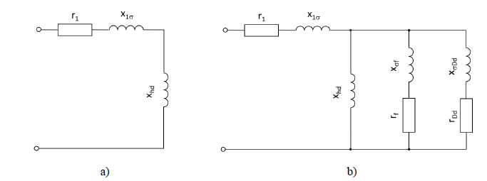
Figure 1 - Common direct-axis equivalent circuits of a synchronous machine for a) stationary operation and b) fast transients (subtransient) operation with field winding short circuited
With the stationary load angle being close to zero for synchronous condensers, the quadrature axis damper winding has much more effect on dampening rotor oscillations than the direct axis damper winding. This can be shown when comparing the locus of the complex synchronising number k() as per (1) (or elastic constant K and damping constant C as per [5], with its real part being the (elastic) synchronizing torque and its imaginary part being the damping.
(1)
with: M … swing of torque produced by the synchronous machine,
… swing of rotor angle, K … elastic constant,
… swing angular frequency, C … damping constant
Despite using slightly different nomenclature, both, Adkins [5] and Bonfert [6], show, that the real and imaginary part of (1) are exactly the factors appearing at the angle and the speed term of the mechanic swing equation (4), which can be derived starting from the swing equation of a simple mechanical (torsional) pendulum (2):
(2)
With: J … moment of inertia, … angle relative to a stationary (non-rotating) reference, C1 … damping factor, K1 … spring constant
The applied torque mA equals zero for a synchronous condenser having neither a prime mover nor a mechanic load.
Re-writing (2) for small sinusoidal swings , dividing the whole equation by the rated apparent torque MS,N = SN/
N and using (3)
(3)
yields (4). Note, that due to division by MS,N, the swing equation, which is in torque, becomes converted to relative units (p.u.).
(4)
It has to be denoted, that for a simple mechanical pendulum described by (2), C1 and K1 are both constants. This is no longer true for a synchronous machine, where both parameters depend upon swing frequency and steady state load point (i.e. rotor angle ).
In Figure 2 a comparison of the locus of 𝑘(Ω) as per (1) is given, with the imaginary part being the damping and the real part being the elastic constant or synchronizing torque constant, of a machine having a complete damper winding and a machine having a so called damper grid. The curves were calculated for a synchronous condenser working on an infinite bus.
Damper grid refers to a damper winding located in the pole shoes and a pole-to-pole connection through the rotor rim, whereas a compete damper winding refers to a design featuring a direct connection of the damper bars through copper rings (or lashes allowing for thermal expansion) across the pole gap.
The main difference of these two designs with respect to machine characteristic reactances is 𝑥𝑞'': For a complete damper winding holds, whereas for damper grids
, with the extent of difference being design-dependent. For the comparison shown in Figure 2,
and
has been used.
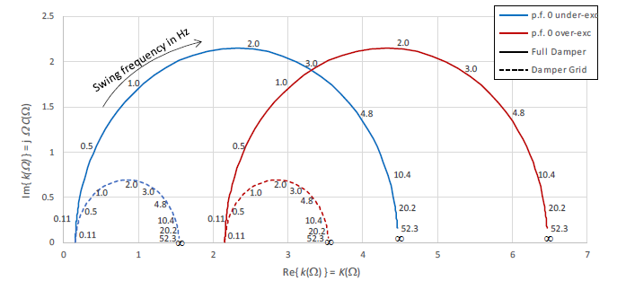
Figure 2 - Comparison of locus of k(Ω) for p.f. 0 under-excited (blue) and p.f. 0 over-excited (red) of a machine having a complete damper winding (–) with a machine having a damper grid (- -)
The subtransient reactance together with the leakage impedance of the step-up transformer are the key factors to determine the short circuit contribution SCC of the synchronous condenser plant. Higher values of SCC and thus lower reactances are regarded beneficial to increase the system strength from a power systems point of view.
The lowest possible value of transformer short circuit voltage is determined by transformer design and is in the range of 0.08p.u. to 0.12p.u. (dependent on design, rating and voltage level).
A synchronous condenser can in principle be designed to have a rather low subtransient reactance. The required resistance to a terminal short circuit and the rigidity of the stator end winding support to achieve that, becomes a challenge for very low values of subtransient reactance. Therefore, this sets a lower boundary for a feasible xd'', from design perspective.
Figure 3 shows a section of a large synchronous condensers end winding.
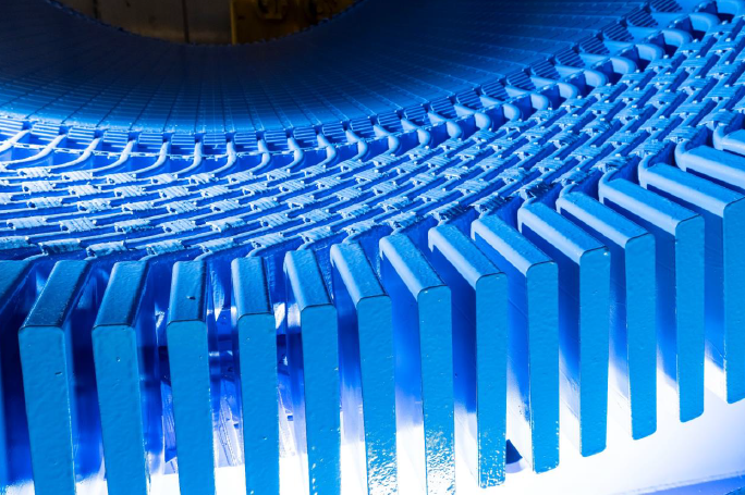
Figure 3 - Stator end winding of a synchronous condenser (salient pole)
In addition, national or international standards might impose further limits. For instance, IEC 60034-3 which is the relevant standard for synchronous condensers in the 60034-series, defines a minimum value of the subtransient reactance of 0.1p.u, if no value was specified by the purchaser.
A further constraint on the maximum short circuit current and in turn on minimum subtransient reactance might be given by the generator circuit breaker which needs to be capable of coping with the short circuit currents arising from a short circuit between the synchronous condenser terminals and the step-up transformer. With typical synchronous condenser ratings below 300Mvar and corresponding short circuit levels, suitable generator circuit breakers can be regarded available for synchronous condenser applications. Short circuit level thus being not a “show stopper”, but rather another economic criterion, if a larger circuit breaker has to be selected. Hence, over-sizing a machine to obtain a higher short circuit contribution is possible and at the end an economic question.
2. Inverse Sequence & Harmonic Current Capability
Unsymmetric loads on the grid inject an inverse sequence current into the network. The effective inverse sequence impedance of the network and all connected equipment seen from the source will define the inverse sequence voltage appearing on the PCC as consequence of the injected current.
All equipment connected to the network will act as a huge (branched) current divider for the injected inverse sequence current. Equipment having a lower inverse sequence reactance will receive a higher share of the injected inverse sequence current, and, because of the branched structure, equipment located closer to the source will receive a higher share as remote equipment.
The inverse sequence reactance of a synchronous machine is determined by the subtransient reactances in direct and quadrature axis, both of them being heavily influenced by the damper system.
An inverse sequence current supplied to the machine will result in an air gap field rotating against the direction of rotation of the rotor. This field acts with double grid frequency on the rotor and will interact with the rotor and its windings.
The first interaction when hitting the rotor will be with the rotor surface, where the inverse sequence field will cause eddy currents with their extent and thus also the losses caused being dependent on the pole design (i.e. laminated tip vs. solid tip). The next interaction will be with the damper winding, where the inverse sequence field induces currents which by trend reduce the magnitude of inverse sequence field (Lenz’s law) linked with the damper winding.
The final interaction will be with the field winding, where the inverse sequence field causes an AC component having double grid frequency on the field current. The magnitude of the AC component being dependent on the amount of inverse sequence but also on the amount of compensation the damper winding can provide.
In heavily under-excited operation with field currents close to zero or in operation with excessive inverse sequence, this AC component can cause the instantaneous field current to become negative. As the normally installed B6(C) rectifier blocks negative current, over-voltages and excitation malfunction could be caused.
Figure 4 shows the calculated field current time trend of a synchronous condenser operating heavily under-excited with minimum field current and being exposed to a 0.1p.u. inverse sequence stator current. As the excitation rectifier was not part of the model, the field current becomes negative during some time and no consequences arise.
The solid, complete damper winding of this studied case limits the AC-component appearing on the field current.
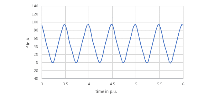
Figure 4 - Field current calculated for a heavily underexcited condenser loaded with an 0.1 p.u. inverse sequence system
The damper winding’s capability to handle continuous and short term negative sequence is limited by its temperature rise and corresponding thermal expansion. Especially for continuous negative sequence, the capability can be influenced by the damper winding’s design. The shorter the loads are, the more important the thermal capacity of the winding becomes.
Similar to inverse sequence, current harmonics generate field harmonics which, in most cases, have, dependent on spatial and timewise ordinal number, a relative movement to the rotor. The effect on the electric machine will thus be similar to the effect of negative sequence.
Loads from inverse sequence and from current harmonics will add up and determine the additional heat sources in the discussed regions/parts of the machine. Therefore, the temperature rises following thereof, should be considered in the design phase of the synchronous condenser.
3. Brushless vs. Static Excitation
In order to allow for reactive power control, synchronous compensators are exclusively wound rotor synchronous machines. The available options with respect to excitation are well-known and apply also to synchronous condensers: The excitation power is either supplied from a brushless exciter machine or a static excitation system via brushes and slip rings.
For static excitation, the required excitation power is typically supplied via the excitation rectifier and an excitation transformer either connected to the station service or directly from a bifurcation located in between step up transformer and the circuit breaker on condenser voltage level. (Other configurations might also be in use) The rectifier (firing angle) is controlled by the automatic voltage regulator (AVR).
To give an order of magnitude, for a condenser in the 170Mvar range, excitation power is estimated in the range of 300 – 500kW (DC; corresponding to about 315 – 525kW AC), with the value being heavily design-dependent.
A static excitation system provides superior transient response and has some specific properties:
- The carbon brushes require some attention: Regular replacement, cleaning / dust removal depending on the cumulated wear and installed brush dust collection equipment
- Compared to brushless excitation, higher excitation power to be supplied by the excitation system.
- Possibility of extending the under-excited operating range with a negative bridge.
Synchronous condenser units which were installed mainly to compensate the reactive power generation of lightly loaded lines (condenser operating under-excited) or to provide short circuit contribution (condenser operating around no-load) may be subject to operation at rather low field currents for extended time, with the brushes being operated outside their optimum operation range with respect to current density and temperature. This is one contributor of increased brush wear rate.
The described configuration for a static excitation drawing excitation power from a bifurcation on condenser voltage level makes clear, that there will be a sag in rectifier supply voltage especially during events, where condensers excitation should be forced to foster the grid support provided by the condenser (i.e. low voltage ride-through LVRT events). To prevent negative impact, the excitation transformer shall be sized such to have sufficient voltage margin at the rectifier.
The other option for excitation, brushless excitation, typically requires just a few kilowatts of power to be supplied to the exciters field winding via a controlled rectifier or a compact excitation which combines AVR and a power circuit. Hence, both brushes and dust can be avoided. The excitation power supplied to the synchronous condensers field winding is generated by the exciter machine by consuming mechanic power from the rotating system. A brushless excitation configuration is less influenced by LVRT events compared to static excitation.
Aside these pros, brushless excitation has also some specifics:
- Brushless exciters, being also an electrically excited synchronous machine, add another time constant to the excitation system, thus have slower transient response and settling times.
- The commonly used rotating diode rectifiers do not allow for negative field voltage. Thus, especially the response for negative slopes is slow.
While the impact from the additional time constant can be (at least partly) compensated by considering a higher ceiling voltage in the excitation system, there is currently no widely available solution to mitigate the lack in negative output voltage available.

4. Reactive Power Capability
For synchronous condensers, the well-known capability diagram of the synchronous machine collapses to a line. The machine runs as a motor and consumes just that much active power from the grid to cover its own losses without field winding I²R and the friction losses on the rest of the shaft line. The field winding I²R loss is covered by the excitation system or the brushless exciter, respectively. The 1-dimensional capability diagram thus does not provide much information any more.
Instead of the conventional capability diagram, another diagram has proven its practical value to depict various limitations of the synchronous condenser: The reactive power capability diagram or Q-V-diagram (names as per [7]), which in the first step shows the required operation range of the condenser plant at the point of common coupling (PCC), which is on the high-voltage (HV) side of the step-up transformer.
Considering the step-up transformers transfer ratio Kt and (leakage) reactance Xt for the selected tap, the (curved) coordinates for synchronous condenser voltage and current can be added. From that, it’s only a small final step to add the various condenser limitations, such as maximum stator current, minimum and maximum field current and limiting stator voltages, if relevant. When working in relative units, it is convenient to also use a relative transfer ratio Kt (instead of the real turns ratio), with its base value being the transfer ratio for the tap to have a transfer of rated primary to rated secondary voltage at no-load.
If only a continuous voltage range and reactive power range are specified, a rectangular shape in the Q-V diagram is obtained. a , Such a chart depicting the relevant limitations from the synchronous condensers perspective is shown in Figure 5. The green shaded area would be the permissible operation range for the step-up transformer’s tap that was selected for this figure. Note that the tap is suitable to cover the upper right area of the required operation range, requiring Kt > 1 p.u. in this case.
Remark: What can be seen from the conventional capability diagram pretty well is, where a machine with rated power factor p.f. = 0 overexcited (i.e. a generator in synchronous condenser operation[1]) differs from a conventional machine having an assumed rated p.f. = 0.85 overexcited. Figure 6 gives an example capability diagram: The field current (or field winding temperature) limit has been pushed outward not to intersect with the “S = constant”-circle any longer.
Pushing the field current limit can be achieved by increasing the cross section of the field winding and thus reducing the I²R loss and/or by improving the cooling of the field winding in addition to the aforementioned on-load tap changer. However, the authors question if there is a practical benefit in the top right and lower left corner in power system operation.
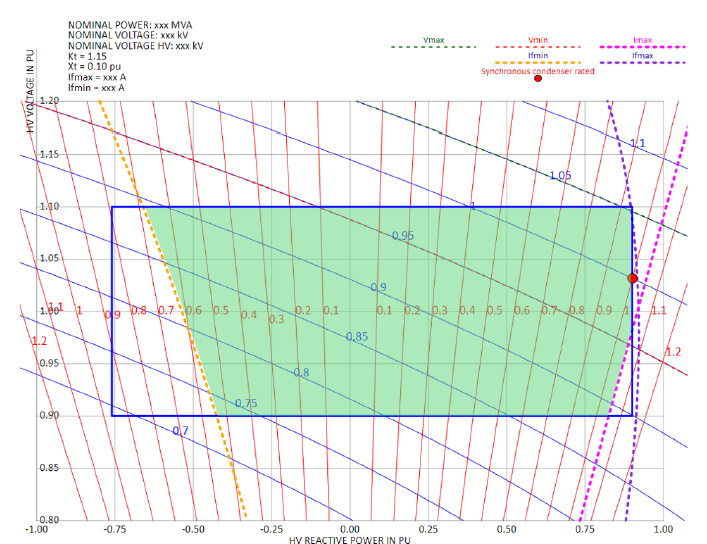
Figure 5 - Reactive power capability diagram (Q-V diagram) at the HV-side of the step-up transformer with added coordinates on synchronous condenser level: thin blue lines: stator current, thin red lines: stator voltage – the red dot indicates the rated operating point (1p.u. voltage and 1p.u. current)
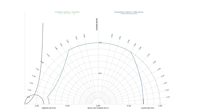
Figure 6 - Capability diagram (rated voltage only) comparing a machine with rated p.f. = 0 (i.e. condenser) with a conventional machine (assumed) rated p.f. = 0.85
The most design-relevant areas in the reactive power capability diagram are the areas around the top right corner (over-excited, overvoltage) and bottom left corner (under-excited, under-voltage). The top-right corner with respect to field current and thus field winding heating, the bottom-left corner with respect to 𝑥𝑑 (minimum excitation and stability), affecting air gap and overall machine size.
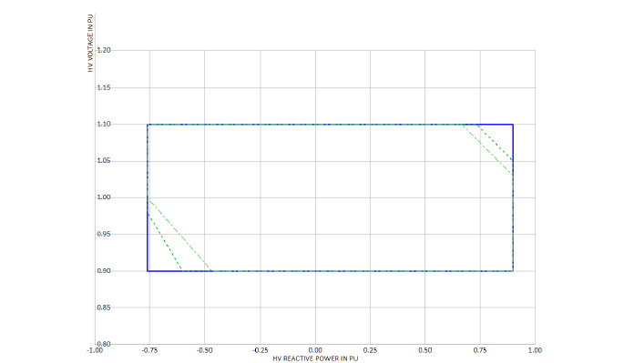
Figure 7 - Exemplary specified operation range of a synchronous condenser plant at PCC – rectangular shape (blue) vs. different extent of clipped corners (green)
When analysing the discussed corners, it can be observed, that operation in those regions is not likely, but would even worsen to the voltage levels in the grid: The region top right of the capability diagram means over-excited condenser operation at over-voltage and thus, by trend, further increasing the systems voltage according to the d𝑣/d𝑄 sensitivity at the PCC. The bottom left region means under-excited condenser operation at already low system voltage, by trend further decreasing the systems voltage. Therefore, operation in those regions might even be detrimental to the systems stability.
As those areas are determining the synchronous condenser design, restricting operation in those areas or even clipping these two extreme corners will yield a more economic condenser solution. Furthermore, it was recognized that the lower left and upper right operating corners are not good engineering practice in terms of voltage control ([8]).
The other two corners (lower right and upper left), are characterized by over-excited operation at under-voltage and vice versa. The diagonal between these two points is therefore the operating area, where the synchronous condenser counteracts the voltage deviation from its nominal value.
5. Salient Pole vs. Round Cylindrical Rotor Design
A salient pole (SP) machine has a considerable amount of air in the q-axis of the rotor (the so-called interpolar space), whereas a cylindrical rotor (CR) with distributed field winding, as seen for turbo generators, has a sequence of slots and teeth around the q-axis.
This results in 𝑥𝑞 being considerably lower than 𝑥𝑑 for the salient pole design, whereas holds for cylindrical rotor designs. The difference between 𝑥𝑑 and 𝑥𝑞 is referred to as “saliency”. Furthermore, for usual 2-pole cylindrical rotor designs 𝑥𝑑 is considerably larger than for common salient pole designs. Figures depend on the source used, e.g. [9], gives for instance a range of
for salient pole and
for cylindrical rotor designs.
A high(er) 𝑥𝑑 limits the under-excited capability of the machine and may thus be not tolerable. From design perspective, it can be reduced by some extent by changing the stator winding and/or air gap and by downrating / upsizing of the machine.
For further comparison, a salient pole machine and a cylindrical rotor machine having identical 𝑥𝑑 and thus identical under-excited capability, are set base. This to focus on the effects connected to the difference in saliency not to be overlooked because of a difference in 𝑥𝑑.
A direct consequence of the different saliency of the two kinds of synchronous machines is a different shape of the theoretical and practical stability limit curves: For the salient pole machine, the theoretical limit is a curve starting at the left end of the reluctance circle, whereas for cylindrical rotor the reluctance circle collapses to a spot and the stability limit it is a vertical line at 1/𝑥𝑑 . Figure 8, which shows also practical limits that were drawn with a safety of 0.1p.u., gives a direct comparison. Note, that the limitation coming from stator end region heating has not been considered in Figure 8.
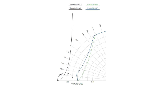
Figure 8 - Theoretical and practical stability limit of a salient pole machine (SP; solid lines) and cylindrical rotor machine (CR; dashed lines) having (assumed) identical xd
Figure 9, which is basically a plot of the well-known relations (6) for active power and (7) for synchronizing power, shows a) the stationary and transient torque vs. load angle characteristics of said machines and b) the synchronizing power, calculated for maximum over-excited output and corresponding excitation held constant.
The torque (in relative units) is equal to the active power in relative units, with the torque base being the rated apparent torque.
The relations and figures shown so far allow for a qualitative assessment and discussion, but are insufficient for an in-depth analysis. For such, the frequency-dependency of 𝑥𝑑 and 𝑥𝑞 as well as the mechanic system (inertia) have to be considered.
While both designs can consume about the same under-excited reactive power, as it was expected because of assumed identical 𝑥𝑑 , there is a significant difference in the stability margin at high under-excited reactive power.
The maximum available under-excited reactive power can also be seen from the relation for the reactive reaction power (reactive power at zero excitation):
(5)
With: 𝑄𝑟 … reactive reaction power, U … terminal voltage, 𝑥𝑑 … synchronous reactance direct axis, 𝑥𝑞 … synchronous reactance quadrature axis, … rotor angle
The 2nd term in the brackets varnishes for 𝜗 = 0, i.e. condenser operation, resulting in equal maximum under-excited reactive power at zero excitation for salient pole and cylindrical rotor designs, if their 𝑥𝑑 is identical.
It is worth noting, that for salient pole machines the boundary given by 1⁄𝑥𝑑 can be overcome by supplying negative field current to the machine, which then allows operation inside the reluctance circle. Operation with negative field current has decreased stability margin which imposes practical limitations and increases complexity of the excitation system.
Similar to Figure 9, Figure 10 shows the stationary and transient torque vs. load angle characteristics of said machines and the synchronizing power, but for the stationary load point at maximum under-excited operation.
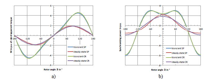
Figure 9 - a) Torque vs. rotor angle and b) synchronizing power (dP/dθ) of salient pole (SP) and cylindrical rotor (CR) at maximum over-excited operation & excitation
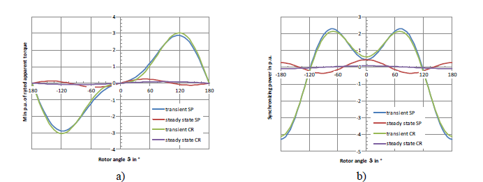
Figure 10- a) Torque vs. rotor angle and b) synchronizing power (dP/dθ) of salient pole (SP) and cylindrical rotor (CR) at maximum under-excited operation (0.1p.u. residual excitation)
Comparing Figure 10 to Figure 9 shows, that the stationary torque as well as the stationary synchronizing torque pretty much varnishes at (very) low excitation / high under-excitation. It is to be noted, that both figures were again drawn for a salient pole and a cylindrical rotor design having (assumed) equal 𝑥𝑑.
The reluctance portion of torque, coming from the significantly different magnetic reluctance of the rotor in d- and q-axis, remains available at the salient pole machine.
(6)
(7)
with P … real power, 𝑃𝑆 … synchronising power, E … synchronous generated voltage
For processes taking place within the transient time constant, such as rapid load changes or disturbances, the transient reactances 𝑥𝑑 and 𝑥𝑞' take the place of the synchronous reactances, with (6) and (7) becoming thus (8) and (9). As subtransient contributions decay very fast, the transient reactance has been used for equations (8) and (9) and the subsequent graphs. This seems justifiable for a qualitative assessment and is also used in electric machines literature such as [5] and [6]. State of the art detailed numerical simulation tools use the complete model of the synchronous machine including also subtransient effects.
For the cylindrical rotor, 𝑥𝑞' represents currents induced in the rotor body in the quadrature axis. 𝑥𝑞' is thus smaller than 𝑥𝑞 , with the value to be very difficult to assess by both, calculation and measurements. Literature specifies a wide range, Bonfert [6], for instance, gives 𝑥𝑞'= (1.5 ...3.0) xd'. xd' has therefore been assumed for Figure 9 and Figure 10. For the salient pole design, xq'=xq holds.
(8)
(9)
with: 𝑃' … transient active power, 𝐸'𝑑0 … voltage appearing behind 𝑥𝑑' in stationary operation, 𝑥𝑑' … transient reactance d-axis, 𝑥q' … transient reactance q-axis, 𝑃𝑆' … transient synchronising power
The 2nd term in (6) to (9) is the contribution coming from the magnetic saliency of the machine.
Another difference is observed in Figure 11. For an exemplary 3Hz/s RoCoF (rate-of-change-of-frequency) event the response for a salient-pole and a cylindrical rotor machine is given. For both machine types, a nameplate rating of 120MVA and an inertia time constant H of 5 s was assumed. The plot shows, that the saliency of a SP reduces the oscillations during and after the RoCoF-event compared to a CR.
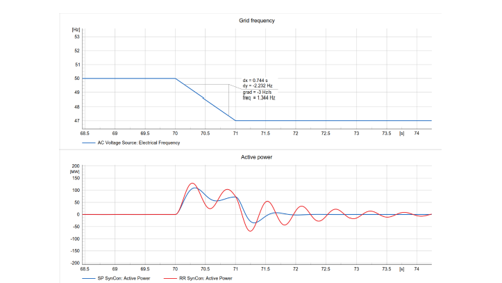
Figure 11 - Top: Applied RoCoF-curve (3Hz/s) Bottom: comparison of the active power exchange during the RoCoF event for a Salient-pole (blue)and a cylindrical rotor (red)

With not much data being publicly available, there seems also to be an difference with respect to stored energy constant between salient pole and cylindrical rotor designs. Data stated in [7] allows to conclude a range for the stored energy constant H resulting from natural inertia 0.5 … 1.5 MWs/MVA for cylindrical rotor designs and 1.5 … 4.5 MWs/MVA for salient pole designs. From experience, with salient pole machines inertia constants of up to 7 MWs/MVA are achievable without flywheel. As H relates to the machines rated apparent power, H can be increased for an existent design by downrating the unit, with the stored energy remaining unchanged. [10] (in German) also presents some data on H, with a similar range as stated before.
If the inertia provided by the machine’s design (natural inertia) isn’t sufficient for the studied application, flywheels can be fitted on both, cylindrical rotor and salient pole condensers, to increase the inertia and stored kinetic energy of the condenser plant. Installing a flywheel requires additional bearings and thus a larger / additional bearing oil skid.
The friction losses of a flywheel can be reduced by lowering the pressure of the ambient it is running in. If the said ambient is not vacuum, circulating the ambient medium (i.e. air) can be used to extract the heat generated by windage and friction loss. If the ambient is (practically) vacuum, extraction of the (although small) friction loss from the flywheel inside a vacuum vessel might require special approaches, with one possibility being sketched in [11].
Fitting a flywheel on a synchronous condenser unit means building a torsional pendulum. Torsional analysis including rotor dynamic analysis needs to be conducted for a proper design of the shaft line and in turn a safe operation. The torsional eigenfrequency of this pendulum is for usual configurations rather low and might be excited from sub-synchronous phenomena. In [11], challenges arising from a flywheel installation are discussed in depth.
Conclusion
Several aspects of designing machines for synchronous condenser application have been addressed. It has been explained how those are influenced by different requirements from specifications and which parts are regarded determining the design (and the costs) of a synchronous condenser.
The authors intended to follow this publication with a paper that deals with operational and transient performance of synchronous condenser machines and the discussion of the short circuit contribution.
References
- “ESO Data Portal: System Inertia - Dataset| National Grid Electricity System Operator.” [online] (accessed Jun. 27, 2023).
- D. Lepour, M. Paolone, G. Denis, C. Cardozo, T. Prevost, and E. Guiu, “Performance assessment of Synchronous Condensers vs Voltage Source Converters providing grid-forming functions,” arXiv:2106.03536 [cs, eess], Jun. 2021, Accessed: Mar. 24, 2022. [Online].
- F. Igbinovia, G. Fandi, Z. Muller, and J. Tlusty, “Reputation of the Synchronous Condenser Technology in Modern Power Grid,” Nov. 2018. doi: 10.1109/POWERCON.2018.8601540.
- D. Dimitropoulos, M. K. Bakhshizadeh, L. Kocewiak, X. Wang, and F. Blaabjerg, “Impact of Synchronous Condensers’ Ratings on Mitigating Subsynchronous Oscillations in Wind Farms,” Energies, vol. 17, no. 7, Art. no. 7, Jan. 2024, doi: 10.3390/en17071730.
- B. Adkins, “The General Theory of Electrical Machines”, Chapman and Hall, London, 1964
- Bonfert, “Betriebsverhalten der Synchronmaschine” (in German), Springer-Verlag Berlin, Göttingen, Heidelberg 1962
- CIGRE SC A1/C4, “Guide on the Assessment, Specification and Design of Synchronous Condenser for Power System with Predominance of Low or Zero Inertia Generators”, CIGRE TB 885, 2022
- AEMO review of technical requirements for connection under Schedules 5.2, 5.3 and 5.3a of the National Electricity Rules March 3rd, 2023 [online], last accessed January .2024
- M. G. Say, “Alternating Current Machines”, Pitman, 1983
- W. Böning (editor), “Elektrische Energietechnik, Band 1 Maschinen” (in German), Hütte Taschenbücher der Technik, Springer-Verlag, Berlin, Heidelberg, New York 1978
- G. Gemelli, F.M. Pepe, A. Oldrati, M. Schenone, A. Stiger, L. Negri, L. Buono, F. Palone, A. Valant, M. Raciti, G. Roveta, L. Callegari, M. Rebolini, “Technical challenges and solutions for the new Terna’s standardized synchronous condensers/flywheel systems”, CIGRE Paris e-Session 2020, Paper A1-304

- [1] A dedicated synchronous condenser would not be able to exchange active power with the grid, despite its own losses. It would have a capability diagram collapsed to a line
