A3 - Long operational experiences of medium-voltage solid-insulated switchgears
Authors
Yuki ISHIKAWA - TEPCO Power Grid, Inc., Japan
Ryosuke ITOTANI - Kansai Transmission and Distribution, Inc., Japan
Satoru MAENO - Mitsubishi Electric Corporation, Japan
Yoshimitsu NIWA - Toshiba Infrastructure Systems & Solutions Corporation, Japan
Hiroyuki SHIRAI - Hitachi Industrial Equipment Systems Co., Ltd., Japan

Summary
Various research and development efforts have been made for switchgears with non-SF6 gases that can replace SF6 switchgears as a measure against climate change. On the other hand, medium-voltage (MV) solid-insulated switchgears have been applied since the late 1960s and significant compactness is achieved by integrally molding live parts of the switchgear with solid insulation materials such as epoxy resin, which has a much higher insulation strength than SF6 gas. This paper describes the excellent operational performance over a period of more than 50 years, outstanding safety, maintenance and inspection efficiency, and long-term reliability of environmentally friendly solid-insulated switchgear (SIS) that does not use SF6 gas. SIS is suitable for installation in buildings and underground spaces due to its small size. Approximately 6 000 units of SIS have been installed especially in narrow spaces such as buildings and underground areas around large cities for utilities, general industries, and transportation facilities. For approximately 3 000 units which have been delivered to utilities, The rate of major failures leading to supply outage over a 50-year period is less than half that of gas-insulated switchgear (GIS), demonstrating the high reliability of SIS. Recent evaluations of SIS operated for approximately 10 to 50 years old in the field were also conducted. They were shipped back to the factory from the field for investigation such as vacuum deterioration of vacuum interrupter and insulation lifetime. As a result, the expected lifetime was evaluated to be approximately 60 years. Furthermore, life cycle assessment (LCA) evaluation results show that the SIS can reduce the total greenhouse gas (GHG) emissions in CO2 equivalent to about 65-70% of that of a cubicle-type gas-insulated switchgear (C-GIS). SIS does not use fluorinated gases or any other high 100-year global warming potential (GWP100) gasses, it has been proven to have a similar or better expected lifetime and reliability compared to GIS, and it has less GHG emissions in CO2 equivalent, in addition to the advantage of compactness. Therefore, SIS can be considered one of the solutions for switchgears without SF6 gases whose applications are expected to be expanded in the future.
Keywords
Carbon-neutral, Compactness, SF6-free, Solid-insulated switchgear (SIS), Solid insulation1. Introduction
Air-insulated switchgear (AIS) and C-GIS using low SF6 gas pressure as the insulating medium are common for 24 kV medium voltage class switchgears. C-GIS is applied, especially when compactness is required. On the other hand, the EU-regulation has been revised to prohibit the use of fluorinated gases or any other high GWP100 gases as a climate change measure. Research and development are under way by various utilities and manufacturers to replace SF6 gas with non-fluorinated gases. CIGRE WG A3.41 has investigated the impact of application of SF6 alternatives on switchgear functions such as current interruption [1]. Seven requirements have been also proposed based on the international investigations and studies of SF6 alternative gas equipment as application guidelines for SF6 alternative gas technology, and SF6 alternative gas equipment are being studied [2, 3, 4]. This paper describes long operational experiences over a period of more than 50 years of SIS which does not use any gases as an insulating medium.
The need for switchgear that is significantly smaller, safer, and more reliable than conventional switchgears had increased due to urban overcrowding in Japan's 24 kV distribution system. SF6 gas switchgear was still under development, and SIS using epoxy resin, which has a higher dielectric strength than SF6 gas, was developed and commercialized since the late 1960s as a solution that could meet the need, successfully reducing the volume to 1/10 of conventional ones [5, 6]. The application of SIS for utilities has expanded mainly in the urban centers of large cities due to urban congestion since the 1970s. It has contributed to the reduction of substation land area and construction costs. Approximately 3 000 units of 24 kV SIS are currently in commercial operation in utilities. SIS for industry use has also been developed and been in commercial operation since the 2000s as a switchgear that was suitable for renewal and expansion in narrow and small electric room. 3 000 units of 24/36 kV rating has been in operation in industries today. There are a combination of product patterns and various product lineup to achieve circuit configurations tailored to customer applications in addition to compactness.
This paper reports the design structure and features of the 24 kV SIS, its abundant operational experiences over 50 years, and the evaluation of its deterioration and projected lifetime using 24 kV SISs that were 10 to 50 years old in the field. LCA of the SIS including manufacturing, installation, long-term operation, and recyclability would also be discussed.
2. Design structure and features
SIS is designed to achieve a significant reduction in the size of the switchgear and improve reliability, safety, and maintainability by adopting a solid insulation method, Figure 1 and Figure 2 show examples of the external appearance and internal structure of a 24 kV SIS [5, 6]. Live parts are molded with a solid insulator. The internal design of the SIS is configured with the mechanism, linkage, and vacuum interrupter (VI) located at the moving side unit. The VI is set in silicone oil for insulation and the silicone oil is sealed with O-rings. The current transformer (CT) is located under the VI. In addition, the upper and lower disconnecting switches are located above and below the VI, respectively. These are connected to the cables and busbars of the stationary side unit. The earthing switch (ES) is located on the upper side of the stationary side unit. The disconnector switches are air-insulated, and the moving side unit is pulled out horizontally by a motor and disconnected from the cable and busbar of the stationary side unit.
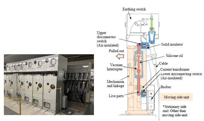
Figure 1 - External appearance of 24 kV SIS — Figure 2 - Internal structure of 24 kV SIS
2.1. Compactness
Significant compactness is achieved by integrally molding live parts of the switchgear with a solid insulator such as epoxy resin. Epoxy resin has a much higher dielectric strength than that of air or SF6 gas. This enables to install the equipment in narrow spaces such as inside buildings and underground. In addition, the compact size makes it easier to transport and install the switchgear on site. Figure 3 and Figure 4 show examples of the volume comparison between 24 kV SIS, AIS and C-GIS. The volume ratio of SIS is approximately 100% compared to CGIS and approximately 40% compared to AIS, for the feeder unit. On the other hand, for the secondary side of the main transformer, SIS is compactly designed, with a volume ratio of approximately 50% compared to C-GIS and approximately 30% compared to AIS. The reduction in building and space requirements for switchgears can lead to a reduction in the construction costs, which may contribute to a reduction in lifecycle costs.
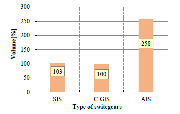
Figure 3 - Example of volume comparison between 24 kV SIS/C-GIS/AIS for the feeder unit
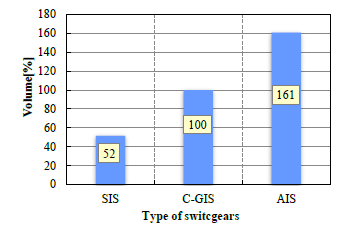
Figure 4 - Example of volume comparison between 24 kV SIS/C-GIS/AIS for the secondary side of main transformer
2.2. Safety and environmental friendliness
All live parts are housed in a solid insulator with a ground potential outer surface such as conductive paint or metallicon to prevent electric shock and ensure safety for some SISs. SIS does not use any fluorine gases with high GWP100 such as SF6 gas [7]. Figure 5 shows an example of the internal structure of 24 kV SIS with ground potential outer surface [8, 9].
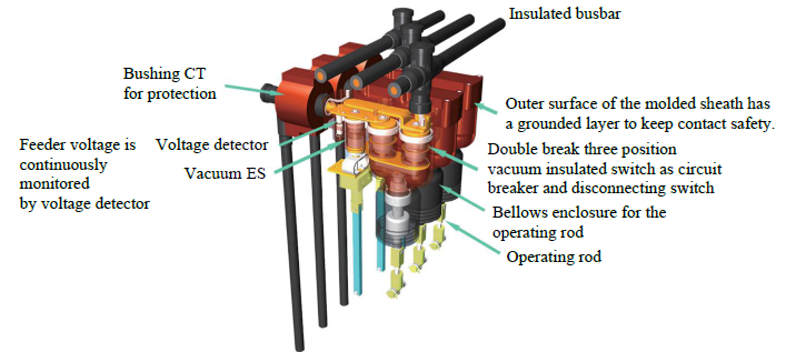
Figure 5 - Internal structure of 24 kV SIS [8]
2.3. Maintainability
The SIS applies a vacuum interrupter which has less electrode wear than that of GCB due to low current density at electrode surface by a diffuse vacuum arc, allowing higher number of operations up to 10 000 times before maintenance. Compact spring-operated or electromagnetic-operated mechanisms with reduced the number of parts is used. Some electromagnetic-operated mechanisms do not require greasing after installation. Gas density monitoring during operation is not necessary. These features can make maintenance intervals longer and reduce maintenance and inspection time, resulting in a reduction of maintenance and inspection labor works. These labor-saving features contribute to human resource savings. Figure 6 shows an example of the internal structure of 24 kV SIS using electromagneticoperated mechanism [7].
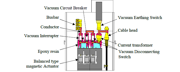
Figure 6 - Internal structure of 24 kV SIS [7]
3. Operational Experiences
3.1. Number of installations
About 6 000 units of MV class SIS have been applied to utilities, general industries, and transportation. Figure 7 and Figure 8 show the number of units applied to utilities and industries. Utilities have applied the switchgear since late 1960s, and the application was increased rapidly in the 1980s, and it has been on a decreasing trend since 2000. Currently, about 3 000 units of 24 kV SIS are still in operation. The application of 24/36 kV SIS into industries has also been expanding since 2000, and they continue to operate today. In addition, SIS of rated voltage 72/84 kV has been applied since 2014 [10].
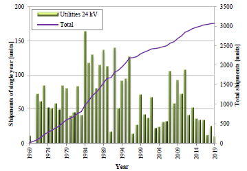
Figure 7 - The number of 24 kV SIS shipped to utilities
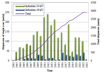
Figure 8 - The number of 24/36 kV SIS shipped to industries
3.2. Operational experience and evaluation of deterioration and lifetime
3.2.1. Surveyed switchgear
Deterioration evaluation was conducted using SISs shown in Figure 1 and Figure 2, which have been applied to a utility since the end of the 1960s. The ratings are as follows:
- Rated voltage: 24 kV
- Rated current: 600/1 500/2 000 A
- Rated interruption current: 25 kA
3.2.2. Failure rate
The failure rate of 3 000 units of SIS that have been in operation for utilities over a period of up to about 50 years was investigated. The major failure rate is about 0,02 /100 CB-bay-year (GIS: 0,05 /100 CB-bay-year* [11]), which is less than half that of GIS, indicating that it has an equivalent or higher level of reliability compared to GIS using SF6 gas. * For GIS of rated voltage 60 kV ≤ U < 100 kV. Figure 9 shows the factors that can lead to major incidents that may cause supply failure. Most major failures were caused by environmental factors. The other factors were incomplete manufacturing, incomplete installation, and age-related deterioration. Environmental factors include surface discharge at disconnectors due to high humidity environments. Failures other than major failures are often caused by incomplete manufacturing, incomplete installation, and age-related deterioration. Symptoms of incomplete manufacturing include abnormal noise, Symptoms of incomplete installation include heat generation due to poor power cable connections, and Symptoms of age-related deterioration include cracks in the outer surface layer of busbars.
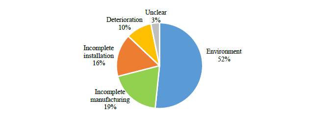
Figure 9 - The causes of major failures leading to supply failure

3.2.3. Deterioration research and lifetime evaluation of SIS in service
Multiple evaluations of service lifetime have been carried out over 20 years using SIS shown in Figure 1 and Figure 2. These SIS were operated in the field for about 10 to 50 years and brought back to the factory for the investigation. As a result, the expected lifetime was evaluated to be approximately 60 years.
3.2.3.1. Insulation deterioration of solid insulation parts
Solid insulation has been confirmed to have extremely high insulation performance compared to gas insulation such as SF6 gas. It has also been shown to have high insulation reliability during long-term operation [12]. The time to dielectric breakdown is normally much longer than 60 years under the operating voltage. On the other hand, partial discharge was observed in some insulation parts of the SIS that had been operated for 47 years. Model test specimens simulating the partial discharge condition of the parts were prepared, and long time voltagetime (V-t) tests with over voltages was performed to evaluate the remaining lifetime.
Figure 10 shows the test specimens and Figure 11 shows the test results. The tests were performed with three levels of electric field strength. Minimum lifetime leading to dielectric breakdown was determined by minimum breakdown time of the three electrical field levels and short time breakdown test. It was estimated that the minimum lifetime would be approximately 15 years when partial discharge continues to occur under the operating voltage. In this case, the partial discharge was caused by the silicone oil penetrating into the insulation parts due to the deterioration of the Oring sealing the silicone oil.
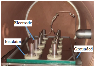
Figure 10 - Test setup of long time V-t tests of epoxy resin molded insulators
It is assumed the partial discharge starts at around 45 years since the expected lifetime of the O-ring is estimated to be about 45 years. Combining it with the 15-year lifetime of the insulation parts in the long time V-t tests, the expected lifetime of the solid insulation parts is evaluated to be approximately 60 years.
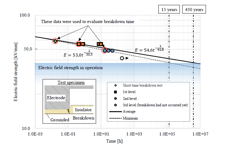
Figure 11 - Dielectric breakdown time of epoxy resin molded insulators
3.2.3.2. Vacuum degree deterioration
Vacuum interrupters that were operated for 7 to 40 years in the field were brought back to the factory and their degrees of vacuum were measured. Figure 12 shows the results. A total of 28 vacuum interrupters were measured, and it was confirmed that the degree of vacuum had decreased to the order of 10-2 Pa compared to the initial degree of vacuum. The annual leakage rate for each valve over a one-year period was estimated using the following formula and statistically evaluated using the average value and standard deviation, which is shown as green lines in Figure 12.
(1)
*Upper limit of control value (manufacturing criterion)
The average value was influenced by data with higher vacuum levels, especially those with more than 20 years of service, causing the data from 7 years of service to deviate from the average. There is still a margin to the performance criterion (on the order of 10-1 Pa) where the dielectric performance between contacts of the vacuum interrupter deteriorates. The expected lifetime is evaluated to be about 60 years if a margin for the replacement is considered to reduce the risks and about half of the performance criterion is set as a replacement criterion.
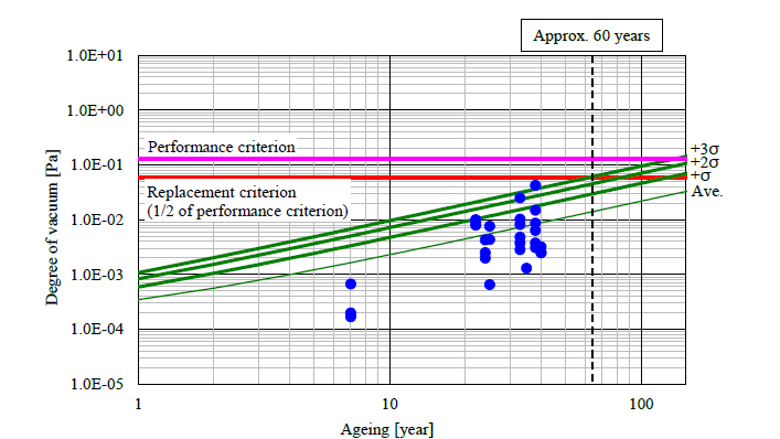
Figure 12 - Relationship between degree of vacuum and ageing
3.3. Life Cycle Assessment evaluation
To evaluate the environmental impacts of SIS, LCA evaluation was conducted for SIS (Figure 1 and Figure 2) and C-GIS. The LCA indicators developed by The Japan Electrical Manufacturers' Association (JEMA) for high-voltage switchgears were used as the quantitative evaluation method [13] [14]. Figure 13 and Figure 14 show examples of CO2-equivalent GHG emissions at each lifecycle phase of SIS and C-GIS. The following conditions were used for the calculations: operation period of 20/40 years, SF6 gas usage of 5 kg for C-GIS (not used for SIS), SF6 gas leakage rate of 0.1%/year, load current of 600 A, and load factor of 50%. The total weight of one unit of equipment is 1 000 kg for SIS and 450 kg for C-GIS. The emission of disposal includes 1% of SF6 gas leakage. Both SIS and C-GIS have the largest percentage of emissions during the operation phase. The ratio of material emission of SIS is larger than that of C-GIS because SIS has a larger material weight (equipment weight) than C-GIS and SIS uses a larger proportion of epoxy resin. The deduction of emission for recycle includes the recycle of metals such as iron, aluminum, and copper. The recycle deductions for SIS and C-GIS are from 1 to 4% compared with the total CO2-equivalent GHG emissions of C-GIS. The higher recycle deduction for SIS compared to C-GIS is due to the higher usage of metals in SIS compared to C-GIS. Although epoxy resin of insulator material is not included in the recycle deduction, its use as a material for external walls after pulverization has been proposed [7], and further considerations for recycling are expected in the future. The total CO2-equivalent GHG emissions of SIS is approximately 70% of those of C-GIS without recycle deduction and approximately 65% with recycle deduction for both 20 years and 40 years operation period. SIS can reduce the total CO2-equivalent GHG emissions and can reduce environmental impact.
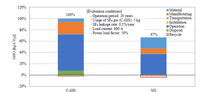
Figure 13 - Example of LCA evaluation for SIS and C-GIS (Operation period: 20 years)
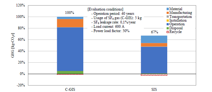
Figure 14 - Example of LCA evaluation for SIS and C-GIS (Operation period: 40 years)
4. Conclusion
Design structure and features, installations and operational experiences of SIS were reported. SIS is compact, environmentally friendly, and has excellent safety and maintainability. Approximately 6 000 units of SIS have been installed as switchgears for utilities, industries, and transportation facilities in small and narrow spaces such as buildings and underground areas around major cities. Among them, around 3 000 units have been installed into utilities since the late 1960s, mainly in the Tokyo metropolitan area, and have been in a good operation for over 50 years. The rate of major failures over 50 years operation is less than half that of GIS, proving that SIS is highly reliable equipment. SIS is expected to have long lifetime; for example, the expected lifetime of the surveyed SIS was approximately 60 years. Furthermore, LCA evaluation has shown that SIS can reduce CO2-equivalent GHG emissions compared to C-GIS. SIS can be one of the solutions for switchgears with non-SF6 gases whose applications are expected to be expanded in the future for mitigating climate change. There are plans to further digitalize the protective control and incorporate sensing functions such as operating time for error diagnosis and prediction in the near future so that maintenance and inspection labor can be further reduced and reliability can be improved.
References
- R. Smeets, et al. “Current Interruption in SF6-free Switchgear” (CIGRE Technical Brochure, Reference 871, 2022)
- T.Uchii, D. Yoshida, S. Tsukao, K. Taketa, K. Tsuboi “Recent Development of SF6 Alternative Switchgear Using Natural-Origin Gases in Japan” (CIGRE 2022 Paris Session, SC A3 No. 10643)
- K. Nakamura “Position on application of substation equipment using SF6 alternative technologies in Japan” (CIGRE e-Session, No. B3-NGN 01, 2020)
- K. Nakamura, S. Tsukao, T. Nishioka, K. Taketa, T. Uchii, H. Hama “Management of SF6 F6 Gas Leakage from Substation Equipment and Technical Guidelines on Application of Substation Equipment using SF6 F6 Alternative Gases in Japan” (CIGRE 2022 Paris Session, SC B3 No. 10736)
- H. Nagata “Solid-insulated switchgears” (The journal of the Institute of Electrical Engineers of Japan, Vol. 92, No.2, 1972 (in Japanese))
- H. Kenmochi, H. Nagata, S. Harada, Y. Shinozaki “Solid Insulation Switchgear (MINICLAD)” (Mitsubishi Denki Giho, Vol. 46, No. 8, 1972 (in Japanese))
- O. Tagaya, Y. Miyauchi “24/36 kV solid-insulated switchgear conforming with environmental requirements” (CIGRE SC A3 and B3 Joint Colloquium (Nagoya), SC A3, Session 2.0, No. 202, 2015)
- K. Sato, et al. “Development of 24-kV Cubicle Type Vacuum-insulated Switchgear (CVIS) for overseas Markets” (Hitachi Review, Vol.58, No.5, 2009)
- T. Okano, et al. “Development of 24 kV Cubicle Type Vacuum Insulated Switchgear (C-VIS)” (The Institute of Electrical Engineers of Japan (IEEJ), Power and Energy Society Annual Conference, 2009 (in Japanese))
- Y. Ohki “Toshiba Achieves Record Delivery of Solid-Insulated Switchgear” (IEEE Electrical Insulation Magazine, Vol. 38, No.3, 2022)
- H. Ito, F. Richert, R. Roux, W. Pepper “CIGRE fourth reliability survey on transmission & distribution equipment” (2023 CIGRE CAIRNS Symposium, SC A3 No. 1115)
- Y. Takahashi et al. “Confirmation Tests for Solid Insulation” (Mitsubishi Denki Giho, Vol. 47, No. 10, 1973 (in Japanese))
- T. Uchii, et al. “Standardized LCA Format for High-Voltage Switchgears Elaborated by JEMA” (The Papers of Joint Technical Meeting on Electrical Discharges, Plasma and Pulsed Power Engineering and Protecting Engineering and High Voltage Engineering, IEE Japan, EPP-23-085, SP-23-027, HV-23-056, 2023 (in Japanese))
- T. Uchii, S. Takahashi, H. Koyama “A Common LCA Format for High-Voltage Switchgears” (CIGRE 2024 Session, 11261)

