D1 - Evaluating the Interfacial Compatibility of Dielectric Materials for Cable Joints
Authors
P. MWASAME, X. WEI, T. PERSON, S. SENGUPTA, M. CHERRY, W. XU, J. CERVA, Y.Q. RAO, J. GU - Dow Chemical, USA
R. DRAKE - Dow Chemical, United Kingdom

Summary
The use of various lubricating fluids during assembly of cable joints, the aging conditions experienced at the cable-joint interface and the use of alternative cable or accessory materials all constitute changes where interfacial compatibility concerns may arise. Formulations of lubricating fluids used in assembling cable joints typically include low molecular weight components, fillers, and proprietary additives, which raises questions about their impact on the durability and reliability of cable systems. Identifying material-selection factors that can impact the long-term performance of cable joints in a laboratory scale evaluation remains an unfulfilled need. This report outlines the design and application of a new measurement test device for evaluating the interfacial breakdown strength of polymer-polymer interfaces. Relevant design variables of a cable joint such as field control elements, compressive stresses, interface topology, interface polymers, and conductor shield can be accounted for, along with thermal aging factors. The measurement capability consists of an electrically stressed interface with a laminate form factor which allows for full flexibility in choosing the interface polymers, the conductive material, conductor shield and any lubricating materials introduced to the interface. Here we focus on a dielectric interface consisting predominantly of silicone rubber (SiR) and cross-linked polyethylene (XLPE) to demonstrate the capability of the interfacial dielectric test device which has been developed.
A thermal-treatment workflow has also been implemented in which lubricating fluid-laden interfaces are held at 90 0C for 7-days at a compressive stress of 0.6 kPa to emulate aspects of aging which mimic operational conditions in a typical high voltage cable joint. We have performed dielectric measurements on unaged and aged samples to compare four commercial silicone-based lubricating fluids. The interfacial dielectric breakdown strength of an unaged sample is ~15kV/mm, with no statistically significant difference in performance across the four lubricating materials. On the other hand, the aged samples show a significant decline of at least 20% in the interfacial dielectric breakdown strength relative to the unaged samples. In independent swelling measurements taken after 7-days, the silicone greases selected exhibit a range of mass uptake between 3wt% and 50wt% with respect to SiR, and no uptake with respect to XLPE. The results imply that the impact of compatibility aspects on dielectric strength can be meaningfully evaluated after an aging protocol. Furthermore, there is no correlation between degree of swelling and magnitude of decline in dielectric strength performance of aged samples.
The results from this study highlight the shortcomings of surrogate compatibility evaluation tests and emphasize the significance of techniques that directly evaluate compatibility aspects under operationally relevant conditions. The testing capability developed can be used to help address questions around what may be defined as a “substantial change” to a previously evaluated cable system and guide decisions on the necessity of pre-qualification tests.
Keywords
Interfacial dielectric strength, breakdown strength, joint, compatibility1. Introduction
Dielectric materials are an essential element in the construction of insulated cables and accessories. The industry has adopted crosslinked polyethylene (XLPE) as a cable insulation material owing to its low cost and excellent dielectric properties. Accessories typically incorporate silicone rubber (SiR) or ethylene propylene rubber (EPR) as a major insulating component, where the elastic nature of these materials facilitate the installation of the joint and sustain compressive interfacial pressure. The contact of disparate dielectric materials in cables and accessories naturally introduces discontinuities in fundamental material properties, including those relevant for dielectric performance. The presence of material interfaces and the local heterogeneity in physicochemical properties introduces weak links and associated failure mechanisms that are unique to the construction of solid-solid polymer interfaces [1].
The confluence of factors at the cable joint such as the variety of materials (SiR, EPDM, XLPE, semiconductive and field grading materials), the use of lubricants during assembly (greases and fluids) and the elevated operating temperature (90oC) attained in high voltage cables necessitates the development of a capability to identify material-selection related factors that impact long term reliability. A review of relevant influential factors associated with material interfaces can be found within CIGRE Technical Brochure 210 (2002): Interfaces in Accessories of HV and EHV cables [2, 3]. The assessment of long-term performance of dielectric interfaces remains a key gap, highlighting the importance of useful material-selection and related diagnostic tools. Today, multiple approaches are used in an attempt to fill this gap. Surrogate experiments, such as swelling of polymers by dielectric liquids, have been used to infer the relevance of material incompatibility at interfaces where such fluids may be present. Although instructive, such experiments themselves do not guarantee the relevance of the specific observed phenomenon towards explaining long-term performance of dielectric interfaces.
Pre-qualification tests and type-testing are utilized to demonstrate compatibility of materials at the interface of high cable joints and such tests include the material design and assembly aspects of high voltage cables systems. However, there is some degree of concern that such tests do not provide sufficient proof of long-term performance and reliability of a cable system [4]. CIGRE Working Group 21.03: Recommendations for Electrical Tests Prequalification and Development on Extruded Cables and Accessories at Voltages >150 kV and ≤400kV [5] identified this shortcoming and made a recommendation to include a long-term test that subjects the cable system to electric stress under heating cycles to probe the reliability aspects. Subsequently, questions remain as to what amounts to a “substantial change” to a cable system that would warrant a new pre-qualification test. Industry would benefit from a laboratory-scale test that would guide such decision making and subsequently reduce the risk associated with electing against performing expensive and lengthy pre-qualification testing when changes are made.
The interfacial dielectric breakdown strength (IBDS) of solid-solid interfaces is typically described in terms of a critical value of electrical stress acting tangentially to the mating surfaces beyond which the insulating system will fail. The impact of interfacial pressure, roughness, elastic modulus, and space-filling liquids on IBDS has been well demonstrated in several literature reports [1, 6-8] through the diagnostic measure of an interfacial breakdown voltage. A typical setup utilized for IBDS measurements [9-12] is depicted in Figure 1. The experimental setups utilized in such testing typically comprise of a mechanical setup in which two polymer pieces are held together side-to-side and placed between two Rogowski-type electrodes that span the interface. The electrodes are connected to a ramped or stepwise increasing high-voltage power source, and the entire setup can be submerged into an insulating oil to reduce the likelihood of flashover. Despite the appeal of this measurement concept, it has several shortcomings. The first pertains to the measurement geometry used. The form factor of the interface and the confinement introduced by the sample holder introduce intrinsic constraints on the mechanical properties of the solid interfaces that can be studied. For example, soft elastomeric materials may buckle and drive additional defects at the interface making determination of the local interface pressure uncertain. A second challenge with existing setups is associated with of the design of ageing studies. For example, in a heat aging, samples are aged in a separate sample holder after which they are transferred into the mechanical test cell [10]. During this process, additional measurement error can be introduced due to movement of the solid interface pieces that can create defects. Finally, the existing measurement setups lack modularity to enable the introduction of additional solid-solid interfaces e.g., insulation-conductor shield, conductor-conductor shield, and insulation-conductor interfaces, that are present in cable joints.
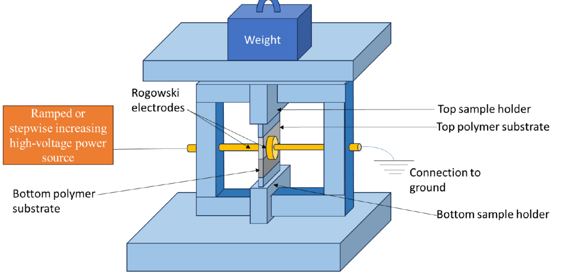
Figure 1 - Generic representation of a common measurement configuration used to evaluate interfacial dielectric breakdown strength (IBDS) of a polymer-polymer interface comprising of polymer A and polymer B
The interfacial dielectric measurement capability introduced in this work aims to overcome the shortcomings of existing measurement methods for interfacial dielectric strength. The critical changes address (1) the test sample form factor, (2) ease of carrying out aging studies under an applied interface pressure and (3) modularity to enable accounting for all electrically relevant solid-solid interfaces. In the discussion that follows, the new capability is applied in an assessment of the compatibility aspects around the selection of dielectric lubricant/grease materials for use at the interface between SiR and XLPE.
A frequently mentioned failure mechanism for cable joints is the swelling of the interface polymer by the dielectric lubricating material used during installation [2]. The hypothesis is that the diffusion-migration of the dielectric lubricant into the polymer substrate leaves air-filled voids which in turn lead to premature dielectric failure due to their relatively low dielectric strength. Thermal conditioning has been introduced as an element of system aging for the assessment of interfacial breakdown strength and has been compared to the results of mass-uptake as a surrogate measure for liquid-solid material compatibility. Details of the measurement capability and method are presented, key results are provided, and a summary of the critical findings is discussed.
2. Materials
The insulation material used is ENDURANCE™ HFDB-4201 SC (a cross-linkable low-density polyethylene), the conductor shield (semicon) is made from ENDURANCE™ HFDA-0801BK (a cross-linkable carbon black-polymer composite), and the silicone rubber is SILASTIC® HV1551-55P (a two-part Pt-curing formulation) all supplied by The Dow Chemical Company. In addition, Powersil® P and Powersil® AP from Wacker Chemie AG are selected as silicone greases in this study. The chemical characterization from safety data sheets describes Powersil® P paste as a polydimethylsiloxane while the Powersil® AP is a polymethylphenylsiloxane; henceforth referred to as Grease P and Grease AP. The methyl terminated PDMS silicone oil used is DMS-T15 (50 Pa-s, CAS 63148-62-9) from Gelest Inc. The phenyl-modified PDMS used is PMM-0025 (CAS 9005-12-3, Gelest Inc) with a viscosity of 500 Pa-s. Finally, a 0.0762 mm (3-mil) thick copper sheet is used to create electrical contacts.
3. Description of the experimental setup
The general development of a measuring capability for interfacial dielectric strength involves two critical steps; first is establishing an appropriate proxy for a dielectric interface in a cable joint and second is determining a method to impose a compressive stress at the interface. This section highlights our approach to these two steps.
3.1. Establishing test device sample mimic of cable joint interface
The interfacial breakdown strength testing device used in this work is realized by combining 4 elements that are summarized schematically in Figure 2. First is the use of SiR to represent one half of the polymer-polymer interface. Second is the use of a carbon black filled composite (conductor shield) to create precisely templated electrodes with controlled spacings. Third is the use of copper foil to ensure good electrical contact between the high voltage leads of the voltage testing unit and the composite electrodes. Fourth is the in-plane assembly of the electrodes in the XLPE polymer substrate. The top polymer (SiR) is obtained by reactive cure of the HV1551-55P two-part SiR formulation to form a 3 mm (125-mil) thick sheet. Equal parts of the A and B part of the SiR formulation are mixed and poured into a 3 mm (125-mil) thick template before degassing in the vacuum overnight and curing at 80 oC in the vacuum oven for 16 hours. The bottom XLPE-electrode combination is obtained by a two-stage lamination process. The first stage involves preparation of individual polymer sheets, followed by a second stage where polymer components are assembled with copper electrode via compression molding press. In the first stage, 1.25 mm (50-mil) thick XLPE and 0.25 mm (10-mil) thick semicon sheets are prepared in the compression molding press at 120 oC under pressure of 0.34 MPa (50 psi) for 4 mins followed by another 4-min pressing at 17.2 MPa (2500 psi). Then these sheets are crosslinked at 180 oC for 15 mins in the press at 17.2 MPa (2500 psi). The 0.25 mm thick LDPE are prepared using the same workflow above without the crosslinking step. Next, 0.25 mm thick semicon electrodes are precisely patterned to form the semicircular shape and the corresponding 0.25mm thick LDPE negative shape template is also cut out using a laser cutter. The copper electrodes, semicon electrodes, and LDPE negative shape template are aligned on top of the 1.25 mm thick XLPE sheet followed by a hot press step under a pressure of 0.28 MPa (40 psi) using 180 oC top plate and 120 oC bottom plate for 10 mins. By placing all components shown in Figure 2(b) in physical proximity, the dielectric interface is created as shown in Figure 2(d). The fabrication process described maintains a controlled geometry, including some control of edge effects, at the “triple point” between the semicon electrode, XLPE substrate, and the opposing SiR. Additionally, lubricating fluid such as that used in cable joint assembly may be added between the polymer substrates.
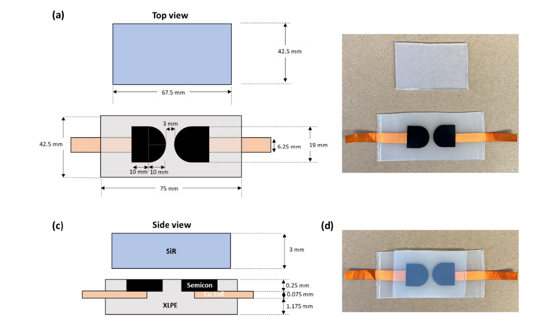
Figure 2 - Illustration of the interfacial testing sample setup with SiR as the top material and semicon electrode embedded XLPE bottom substrate. Images on left hand side not to scale
Some key distinctions between the laminate form factor device reported in Fig. 2 and prior efforts in the literature [13] include (1) the electrode assembly is in plane with the interface, (2) the electrodes are permanently fixed minimizing any additional contributions to the measurement error during handling and assembly, and (3) the electrodes are constructed of semiconductor shield composites allowing for the characteristics of the field control elements in cable accessories to be incorporated.

3.2. Establishing a method to impose a compressive stress at the interface of the test sample
We have also developed a quantitative test frame, shown in Figure 3, to apply interfacial pressure on the test device to mimic the in-built compressive stress of a cable joint sleeve. It comprises of a spring-loaded platform that sandwiches the test device sample against a fixed surface. The compression force of the spring is controlled by tightening or loosening the four steel screws on the top four corners of the mechanical frame. The value of the applied interfacial pressure can be determined from knowledge of the projected area of the test sample together with the force-spring distance calibration curve. It has been found useful to tighten the screws with the test frame in a state of pre-compression as applied by an Instron Test Machine.
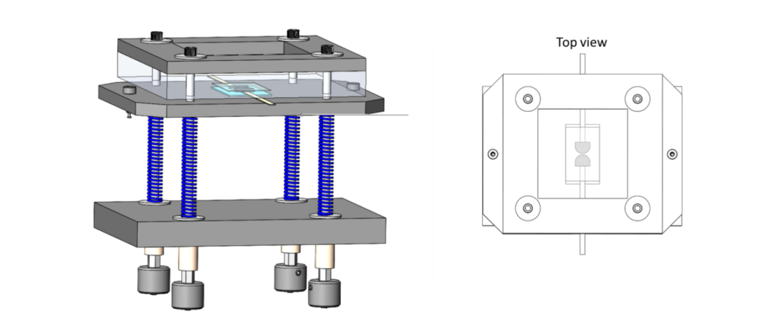
Figure 3 - A schematic representation of a test sample in the quantitative test frame developed to provide a compressive stress on the dielectric interface
4. Experimental methods
4.1. Breakdown test
To prepare the testing samples, a generous amount of interfacial liquid was applied to the top surface of the bottom XLPE-electrode substrate using a tongue depressor. A piece of SiR sheet (6.75 cm by 4.25 cm) was introduced on top of the interfacial liquid. Macroscopic air bubbles trapped in the interfacial liquid during testing sample preparation were squeezed out of samples to avoid unexpected electrical breakdown events in those voids. Excess interfacial liquid was removed from the material interface in the same fashion. To account for the surface preparation process used during installation of real cable joints, the XLPE interface region was sanded using a 60-grit sandpaper in a uniaxial direction for 100 strokes, and then wiped with isopropanol wipes. This process creates microgrooves on the XLPE surface with an RMS roughness of 10 microns as characterized using a stylus profilometer. No residual grit on the resulting surface was observed under optical microscopy.
Samples were then loaded into the test frame described in Figure 3. To study the effect of pressure on the interfacial breakdown strength, the bolts are tightened down to apply about 0.6 MPa on all samples in this study. After loading the sample in the test frame with desired pressure applied, copper electrodes were then connected to the AC voltage tester (Hipotronics 700 series). A ramping AC voltage was applied to samples with a ramping rate at 0.5 kV/s. The maximum voltage was set at 70 kV, with sensitivity at 50%, and overcurrent at 25 mA. A breakdown voltage was recorded after the breakdown event (ACBD test). To calculate the interfacial breakdown strength, the breakdown voltage was then normalized by the distance between the two semicon semicircles (Figure 4b). We have observed that almost all the dielectric breakdown events occur between the two electrodes (see Figure 4c). This implies that the dielectrically relevant area of the interface that is probed during the test is the denoted by material that lies between the two semicon electrodes.

Figure 4 - (a) A breakdown voltage was recorded after an AC voltage test with a ramping voltage at 0.5 kV/s. (b) The distance between two semiconductive electrodes was measured to calculate the interfacial breakdown strength. (c) An example image of a sample with interfacial liquid after the breakdown test
4.2. Swelling test
Mass uptake of silicone rubber exposed to different silicone fluids/greases, was determined by immersing silicone rubber squares (2.54 cm x 2.54 cm) into the silicone fluids/greases in glass jars and maintaining the samples at 90 oC. The initial mass of silicone rubber squares was recorded before the swelling experiment. After immersing into silicone fluids/greases for certain periods of time, silicone rubber squares were taken out of glass jars, cleaned with Kim wipes to remove the excess fluid/greases on the surface, and weighed again to calculate the mass uptake compared to the initial mass. Samples were immersed in silicone fluids for a few hours (noted as 0.1 day), 7 days and 14 days. The average mass change reported is based on three samples for each condition.

4.3. Aging test
To simulate an accelerated aging process, laminate samples with different interfacial liquids/greases were loaded into the rectangular test frame with an applied pressure ~0.6 MPa on each sample. The rectangular test frames with samples under pressure were then introduced to oven at 90 oC. After 7 days of aging, the test frames were removed from oven, and the interfacial breakdown voltages were measured on those samples. The calculated breakdown strength values were then compared against those taken from unaged samples to understand the impact of the aging treatment applied.
5. Results and discussion
The swelling data in Figure 5 shows the performance of the four silicone-based fluids/greases with respect to a silicone rubber material at 90 oC. Those results (of three specimens in replicate) show that the mass uptake follows the trend of DMS-T15 (PDMS fluid)>Powersil® P>PMM-0025 (phenylated-PDMS fluid) ~Powersil® AP with a range from 3 wt% to 50 wt%. Furthermore, the data suggests that the most significant mass uptake of the silicone fluids occurs over 7 days. If swelling is an indicator that is at all relevant to the aging mechanism at the interface, this result suggests that an aging period as short as 7-days can be useful to understand compatibility effects on the interfacial dielectric breakdown strength under aging conditions. The data also shows that the PDMS-based dielectric fluids swell SiR significantly more than the phenylated-PDMS fluids. The lower swelling of SiR by phenylated-PDMS fluid is attributed to the chemical incompatibility induced by the presence of the phenyl moiety on the PDMS backbone. Additionally, both XLPE and semicon showed negligible mass uptake with respect to the four dielectric fluids in separate swelling experiments. Therefore, we conclude that only SiR takes up the dielectric lubricants added to the SiR/XLPE interface.
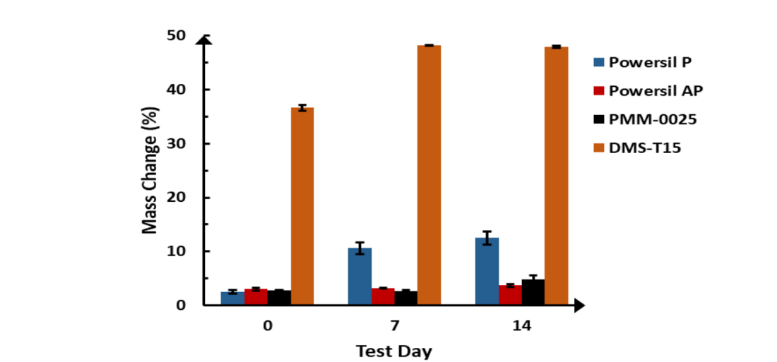
Figure 5 - The mass uptake of SiR from different silicone-based fluids/greases at 90 oC for different time periods. Note day 0 measurement is taken a few minutes after preparing the test device
To investigate the relationship between the degree of swelling and interfacial dielectric strength, breakdown voltage measurements taken at a few mins (noted as day 0 representing unaged testing conditions) are compared against those taken at 7 days for the four liquids. The data in Figure 6 summarizes the key trends observed with the interfacial breakdown stress represented as an average of five evaluations (too few to justify meaningful use of Weibull statistics). First, we do not see a strong correlation between the interfacial dielectric breakdown strength at day 0 and the type of silicone fluid utilized. In principle, this means that for a well-applied interfacial silicone fluid/grease, there is no clear preference for selection of a specific silicone fluid based on the initial breakdown strength data. Furthermore, the breakdown strength of the test device samples with interfacial silicone fluid is significantly higher than that without. This highlights the benefit of an interfacial fluid in elevating the dielectric breakdown strength of an interface. When we compare the 7-day interfacial dielectric breakdown strength results to the initial values, there is a statistically significant reduction in performance across all the silicone fluids/greases studied. Powersil® P and Powersil® AP silicone greases do not have any statistically significant differences in breakdown strength performance at day 0. However, they both show about 40% decline in the average breakdown strength after 7 days relative to the initial breakdown value despite differences in mass uptake during swelling of 10 wt% and 3 wt%, respectively. In addition, these two silicone greases also have a similar decline in performance compared to PMM-0025 silicone oil. While these results are consistent with literature reports [9, 11], they further imply that having low swelling effect on silicone rubber is not sufficient to ensure good long-term performance of a roughened fluid-laden dielectric interface. DMS-T15, which has the largest swelling of the SiR among the silicone fluids also exhibits the lowest 7-day dielectric breakdown strength value about 3 kV/mm. This value is comparable to a roughened SiR-XLPE interface without applying any interfacial liquid, suggesting that the mass uptake of DMS-T15 is severe and essentially depletes the interfacial fluid from the dielectric interface. The superior 7-day performance of Powersil® P compared to the DMS-T15, despite both being non-phenylated, is hypothesized to be due to a significantly slower rate of diffusion of the base oil in that formulation, presumably due to its higher molecular weight.
Finally, we note that the ranking of the resistance to mass uptake after 7-days of the dielectric fluids by SiR (Powersil® AP~PMM-0025>Powersil® AP>DMS-T15) does not correlate with the magnitude of decline seen in the 7-day aged interfacial breakdown strength values of the corresponding fluids. We believe that this is evidence of a yet-to-be elucidated material property/mechanism that needs to be accounted for to fully explain the observations in this work.
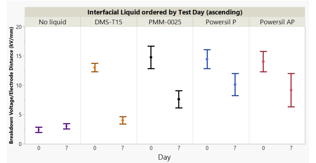
Figure 6 -The comparison between day 0 and day 7 performance for dielectric interface with different silicone fluids/greases. Note day 0 measurement is taken a few minutes after preparing the test device. The interfacial breakdown stress represents the average of five tests
6. Conclusion
This paper documents important progress made in developing a practical method to directly evaluate the interfacial compatibility of materials utilized in dielectric interfaces. Specifically, we report the application of a new interfacial dielectric strength measurement device that can be utilized within an accelerated aging test protocol to infer the long-term compatibility of fluids used in dielectric interfaces. We have investigated the role of mass uptake of a dielectric fluid at a SiR-XLPE dielectric interface on the long-term performance of dielectric cable joints. The diagnostic measurement of the initial dielectric breakdown strength and that of 7-day aged samples reveals that the 7-day performance significantly declines for both high and low swelling silicone fluids. This result raises questions on the relevance of surrogate swelling tests to assess interfacial compatibility and related reliability assessments based on the principle of mass uptake, towards the development of high performing material interfaces. The experimental capability and workflows highlighted represent an improved laboratory-scale method that can be utilized to directly evaluate compatibility aspects of developmental materials for the cable joint and accessory application.
References
- E. Kantar, “Dielectric Strength of Polymeric Solid–Solid Interfaces under Dry-Mate and Wet-Mate Conditions,” Energies, 2021. 14(23): pp. 8067.
- H. Geene, “Interfaces in Accessories for Extruded HV and EHV Cables in Accessories for HV and EHV Extruded Cables: Volume 1: Components,” CIGRE Green Books, 2021. pp. 81-96.
- CIGRE Study Committee B1: Insulated Cables, “Accessories for HV and EHV Extruded Cables: Volume 1: Components” CIGRE Green Books, 2021.
- E. Pultrum, W. Sloot, and J. Fernandez, “How to perform a prequalification test – interpretation of the standard,” 9th International Conference on Insulated Power Cables, 2015.
- Recommendations of the CIGRE WG 21.03, “Recommendations for electrical tests (prequalification and development) on extruded cables and accessories at voltages 150 (170) kV and ≤ 400 (420 kV),” Electra No. 151, 1993.
- E. Kantar et al., “Longitudinal AC breakdown voltage of XLPE-XLPE interfaces considering surface roughness and pressure,” IEEE Transactions on Dielectrics and Electrical Insulation, 2017. 24(5): p. 3047-3054.
- E. Kantar, F. Mauseth, E. Ildstad, “Effect of pressure and elastic modulus on tangential breakdown strength of solid-solid interfaces,” IEEE Electrical Insulation Conference (EIC), 2016.
- D. Panagiotopoulos, “AC Electrical Breakdown Strength of Solid Solid Interfaces: A study about the effect of elasticity, pressure and interface conditions,” 2015.
- D. Fournier, L. Lamarre, “Effect of pressure and length on interfacial breakdown between two dielectric surfaces,” Conference Record of the 1992 IEEE International Symposium on Electrical Insulation, 1992.
- Z. Li et al., “Morphology evolution and breakdown mechanism of cross‐linked polyethylene (XLPE)–silicone rubber (SiR) interface induced by silicone grease diffusion,” High Voltage, 2022. 7(4): p. 802-811.
- E. Ildstad, R. Dale, E. Kantar, “Longitudinal Breakdown Strength of Wet-mate Solid-Solid Interfaces at VLF and 50 Hz AC voltages,” Proceedings of the Nordic Insulation Symposium, 2022.
- Y. Chen et al., “Insulating polysiloxane coating for XLPE‐Si‐rubber interfaces with high long‐term stability,” Polymer Composites, 2020. 41(9): p. 3501-3509.
- K. Wu et al., “Electrical Resistance Performance of Cable Accessory Interface Considering Thermal Effects,” Materials, 2023. 16(11): p. 4122.

