B4 - Hydro-Québec’s Châteauguay back-to-back HVDC converter replacement project: Integration of new operating modes for system resiliency improvement and water management effectiveness using VSC-HVDC
Authors
Amr ABDELLAOUI, Vito DE LUCA, Marie-Jacinthe HEMSAS - Hydro-Québec, Canada

Summary
The Châteauguay substation, commissioned in 1984, is a strategic facility within Hydro-Québec’s transmission system and a major component of the Châteauguay-Massena Interconnection that ensures energy exchanges between the Province of Québec and the State of New York. It accomplishes asynchronous power transfers between Hydro-Québec’s 735 kV transmission system and New York Power Authority’s (NYPA) 765 kV transmission system using two 500 MW back-to-back line-commutated converters (LCC).
The interconnection also plays a unique role in the operation of the Beauharnois generating station, a run-of-the-river hydroelectric power station along the St. Lawrence River. Beauharnois generating units are synchronized onto the New York grid by way of the Châteauguay substation, making the substation essential for the evacuation and transmission of Beauharnois’ generating capacity.
The existing converters at the Châteauguay substation are expected to reach the end of their useful life in 2024. A replacement project was initiated in 2020 to ensure continued and reliable energy exchanges between Hydro-Québec and NYPA. The objective of the project, which is expected to be commissioned in 2027, is to replace the existing LCCs with two back-to-back voltage source converters (VSC), each with an upgraded capacity of 750 MW. With a total converter capacity of 1,500 MW, the project will be among the largest of its kind and the first ever to use VSC technology for a back-to-back application at 735 kV and 765 kV.
The new converters will directly interface with the 735 kV and 765 kV buses of the Châteauguay substation, requiring a significant overhaul of its current configuration. These changes, as well as the substation’s aging infrastructure, provided an opportunity to reevaluate its entire topology and integrate the notion of water management and system resiliency into the future operation of the interconnection. Thus, a new thoroughly analyzed topology was proposed to improve the operational reliability of the interconnection and the adjacent regional subsystem, and to ensure the continuity of power delivery from the Beauharnois power station.
Furthermore, VSC technology combined with a redesigned substation topology led to the development of new operating modes, such as islanded and blackstart modes. These new operating modes facilitate microgrid operation of islanded load and generating units, which would significantly mitigate post-contingency spills at the Beauharnois generating station and increase system flexibility in severe post-contingency conditions.
This paper presents the scope of Hydro-Québec’s HVDC converter replacement project at the Châteauguay substation from a planning and operational perspective. Although VSC-HVDC is less common for back-to-back applications, the paper will discuss the technical considerations that influenced the decision favoring VSC over LCC for the project. It outlines VSC’s principal benefits for the bulk system and for the operation of a large nearby hydroelectric generating complex. The paper also thoroughly describes the development of innovative operating modes and system configurations, made possible by the new VSCs, and how these new operating strategies can improve reliability, increase the effectiveness of water management and mitigate post-contingency spills of the nearby Beauharnois generating complex. Lastly, the paper explores grid forming control (GFM) for the proposed operating modes using EMT simulations.
Keywords
Back-to-Back HVDC, Blackstart, Grid Forming Control, Islanded Operation, Reactive Power, Resiliency, Run-of-the-River Hydro, Transmission System Planning, Water Management, Voltage Source Converter1. Introduction
The Châteauguay substation, located southwest of Montréal, Québec, Canada, is a highly strategic facility within Hydro-Québec’s (HQ) transmission system. It is the central component of the Châteauguay-Massena Interconnection (CHAT-MASS) that ensures energy exchanges between the Province of Québec and the State of New York, and supplies local load as well as tie lines with the Province of Ontario. With a maximum export capacity of 1,800 MW and an import capacity of 1,000 MW, CHAT-MASS is HQ’s second largest interconnection and provides access to a vital backup supply source from New York, ensuring system reliability during winter peak periods. Commissioned in 1984, the HVDC converter section of the substation comprises two 500 MW back-to-back (BtB) thyristor-based line-commuted converters (LCC) which are connected to a 90 km, 765 kV tie line between Châteauguay and the Massena substation in upstate New York (the MSC tie line). The converters are of critical importance, from both an operational and a market perspective, as they constitute the main equipment that makes electrical energy exchange possible between HQ’s and the New York Power Authority’s (NYPA) transmission systems, which are asynchronous to each other.
The Châteauguay substation also plays a unique role in the operation of the nearby Beauharnois generating complex (BHN), a 1,900 MW run-of-the river hydroelectric power station composed of 36 generating units located along the St. Lawrence River. Sections of the BHN complex are radially connected to the substation by four 120 kV lines, forming what is referred to as the Beauharnois-Châteauguay complex (BHN-CHAT). When the interconnection is operated in export mode, BHN generating units are synchronized to the New York grid, effectively aggregating a portion of BHN’s generating capacity to the power delivered by the converter to achieve scheduled export power levels on the MSC tie line. Another of BHN’s key functions is to manage the river’s water levels. System contingencies that lead to the tripping of BHN units result in water spills. Consequently, maintaining continuous power transmission of BHN generation via the Châteauguay substation is critical for the water discharge of the Beauharnois Canal and for the continuity of maritime traffic along the St. Lawrence Seaway.
The existing converters at the Châteauguay substation will be considered to have reached the end of their useful life by 2024. HQ’s comprehensive end-of-life study concluded that replacing the converters was the solution that would best ensure continued and reliable operation of the interconnection. The existing LCCs will be replaced with two new BtB IGBT-based voltage source converters (VSC), each with an increased capacity of 750 MW. The upgraded converters will directly interface with the substation’s 735 kV and 765 kV busbars, requiring a reconfiguration of the substation’s current topology. Construction is already underway, with commissioning expected in 2027. Upon completion, Châteauguay’s new 1,500 MW HVDC converter station will be among the largest of its kind and the first to use VSC-HVDC technology for a BtB application at 735 kV and 765 kV voltage levels.
This paper presents the scope of HQ’s HVDC converter replacement project from both a planning and an operational perspective. It will discuss the rationale behind HQ’s unique solution, specifically highlighting the technical factors that played a pivotal role in HQ’s decision favoring converter replacement over lifetime extension and its opting for VSC-HVDC technology over LCC-HVDC. The paper will outline the principal benefits of using VSC for a BtB HVDC station located near a large run-of-the-river hydroelectric generating complex. It will also present a series of new proposed operating modes and system configurations made possible by the new VSCs and describe how these new operating strategies can improve reliability and increase water management effectiveness at the BHN complex. Lastly, the paper presents exploratory EMT simulations of the new operating modes presuming grid forming controls (GFM).
2. Existing Configuration and Constraints of the Châteauguay Substation
2.1. Description of the Existing Configuration
The Châteauguay HVDC converter station sits adjacent to two AC switch yards, one at 735 and 315 kV, operated at HQ’s system frequency, and the other at 765 and 120 kV, operated at NYPA’s frequency. As illustrated in Figure 2.1, the two existing BtB LCCs are configured as two independent symmetrical monopoles, with one terminal of each pole connected to the substation’s 315 kV busbar (HQ side) and the other terminal to the 120 kV busbar (NYPA side). On the HQ side, three 735/315 kV transformers ensure power transfers between HQ’s 735 kV network and the converters, while simultaneously supplying the load of the local subsystem. On the NYPA side, the 120 kV busbar serves as a collector bus for power supplied by the converters and by BHN and is connected to the MSC tie line via four 120/765 kV step-up transformers, one of which is normally used as a reserve (not shown in the diagram). The HVDC converter station is equipped with filters on both sides, and shunt compensation equipment on the HQ side for AC voltage regulation. Two static var compensators (SVCs) are also connected to each converter’s 120 kV terminal, providing reactive power support and ensuring successful converter active power recovery following severe voltage dips on the 120 kV side [1].
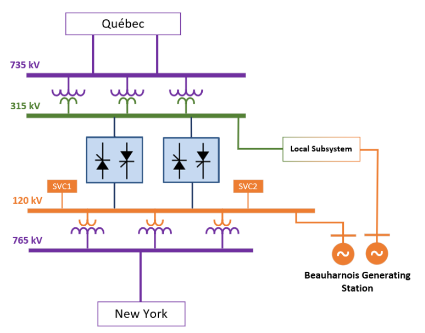
Figure 2.1 - High level representation of the existing Châteauguay substation
2.2. Operational Modes and Constraints
The conventional operating strategies of the existing BtB converters can be classified into two sets of operating modes: 1) Forward mode, where power is directed toward NYPA’s system, and 2) Reverse mode, where power is directed toward HQ’s system. While mainly used in import configurations, reverse mode is also used in specific export configurations to modulate the tie line’s power transfer generated by radially connected BHN units.
The complexity of BHN-CHAT configurations and the intertie’s low short-circuit ratio (SCR) resulted in operational challenges in the early stages of the converters’ operation, prompting modifications of converter control systems and the installation of additional filtering equipment [1]. Despite improved performance, operation remains complex and contingent upon the availability of numerous types of equipment within the BHN-CHAT complex. For example, to operate both existing LCC poles in forward mode, sufficient short-circuit levels must be maintained at the 120 kV terminal, requiring at least three 120/765 kV transformers to be in service. An N-1 contingency involving the loss of one of these transformers results in a forced outage of one LCC pole, which in turn reduces the total HVDC output by 500 MW. Moreover, full capacity operation also depends on the availability of converter transformers, filters, reactors, and SVCs.
2.3. HVDC End-of-Life Assessment
Châteauguay’s HVDC converters began to show evidence of deterioration as early as 2007, despite the generally expected lifespan of 40 years for such converters. Several replacement and refurbishment projects have been completed since then to ensure the converters continue to function reliably. However, the number of converter component failures affecting the availability of the interconnection has risen sharply in recent years, due in large part to the degrading operating condition and the obsolescence of the station’s major components, such as power transformers, thyristor valves, filters, and cooling systems. Failures in such equipment can cause prolonged converter downtime. Moreover, maintenance has become problematic as many essential spare parts are no longer readily available on the market. Further extending the life of the existing converters using a piecemeal approach was determined to be less cost-effective in the long run and would not achieve the same level of reliability provided by new converters. Refurbishing or retrofitting the existing converters was also found to be unfeasible, since it would require significant modifications to the converter building and prolonged interconnection unavailability. A replacement project using a Greenfield approach was thus preferred.
3. Description and Technical Justifications of the Proposed Solution
A comprehensive study concluded that replacing the aging converters with two new 750 MW VSCs connected at 735 and 765 kV was the most cost-effective and technically superior solution. The proposed connection scheme of the new converters is illustrated in Figure 3.1.
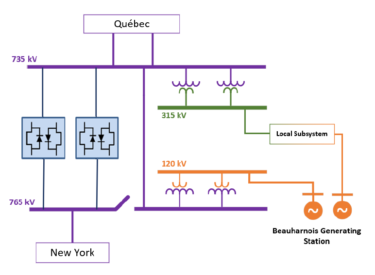
Figure 3.1 - High level representation of the proposed Châteauguay substation
3.1. Advantages of VSC-HVDC Technology
Although less commonly employed for BtB configurations, VSC-HVDC technology proved to be the most suitable option for the new converters, in light of the technical particularities of both the CHAT-MASS interconnection and the BHN-CHAT complex. Lack of commutation failure, reactive power control capability, and superior performance in low SCR applications are some of the features that made VSC the preferred choice. The many technical advantages of VSC-HVDC technology in a BtB application at Châteauguay are outlined below.
3.1.1. Increased Interconnection Flexibility and Reduced Operational Constraints
Implementing VSC-HVDC technology at Châteauguay would eliminate the need to maintain a stringent minimum short-circuit current, allowing the HVDC station to operate at full capacity regardless of the number of in-service 735/315 kV or 120/765 kV transformers. This would alleviate the interconnection’s current operational restrictions and eliminate the effect of any transformer contingency on the HVDC power transfer. The VSCs’ ability to generate reactive power also eliminates the need for additional compensation devices such as capacitor banks and SVCs, and reduces requirements for harmonic filtering. The resulting HVDC station would incorporate fewer key components essential for converter functionality, thereby simplifying overall operation, reducing maintenance costs, and improving overall reliability.
3.1.2. Connection at 735 and 765 kV
VSC technology makes connecting to higher-voltage networks more feasible, resulting in significant operational benefits and incidental cost savings when the overall end-of-life and upgrade investments forecasted at the Châteauguay substation are considered. The connection of the new converters at 735 kV and 765 kV will allow power flow to essentially bypass the substation’s AC transformer sections, thereby reducing the number of transformers required to meet design criteria. Load flow studies showed that only two of the four 120/765 kV transformers and two of the three 735/315 kV transformers would be required to meet the substations’ current and anticipated capacity needs. Considering that most of these transformers are earmarked for replacement within the coming decade, the leaner transformer station design would reduce long-term replacement costs, as opposed to a scenario reprising LCC-HVDC technology and the existing 315/120 kV configuration, even after factoring in the greater costs of the higher-voltage rated VSC-HVDC.
This new connection scheme is particularly advantageous for the 735/315 kV station because it frees up valuable transmission capacity that is essential to supplying the local subsystem load. In the current configuration, power flow on the three 735/315 kV transformers is expected to soon exceed the substation’s transformation capacity in export conditions. The suboptimal configuration of the transformers at the 735 kV busbar and the lower rated capacity of one of the transformers reduce the substation’s transfer capacity and would require a major overhaul of the 735/315 kV station to remedy the situation. The new connection scheme eliminates the need for the third transformer and allows HQ to avoid costly remedial upgrades.
3.1.3. Voltage Stability
For HQ’s unique transmission system, characterized by extensive transmission lines and power generation primarily located some 1,000 km from the main load centers, power system stability is critical. Having enough strategically located and fast-acting reactive power compensating devices is crucial to the reliability of the transmission system. Driven by consumer-side decarbonization, demand for electricity is expected to increase significantly in the coming years, which may prompt the need for system reinforcements to increase voltage support.
The Châteauguay substation is connected to HQ’s main 735 kV bulk system via two lines, forming the southwestern part of the 735 kV loop that encircles the Greater Montréal area (GMA), commonly referred to as the Montréal loop. Generation located in northern Québec and Labrador is supplied to the Montréal loop by a series of 735 kV lines grouped into two major transmission corridors, one extending northwestward up to the La Grande hydroelectric complex and the other extending northeastward toward Churchill Falls. Given the rapidly growing load of the GMA, the Châteauguay substation may become subject to voltage stability issues in certain system configurations. In this context, utilizing VSC-HVDC technology for the new converters would be advantageous as it provides reactive power support to the transmission grid, a capability that is lacking in LCC-HVDC technology. The new converters will contribute to fault recovery and mitigate voltage collapse issues by varying the reactive power output to control the voltage at the given terminals to maintain the desired power flow under possible system disturbances and contingencies [2]. Each converter will be designed to provide ±247 Mvar of reactive power for the full range of the converter’s active power capability and can also be operated as independent STATCOM devices when active power is null.
To demonstrate the advantages of VSC-HVDC over LCC-HVDC in the context of static and dynamic voltage stability, load flow and transient stability simulations were conducted using power system simulation and analysis software, generating P-V curves and post-contingency dynamic voltage response results. Two versions of the same network base case model were used for the simulations, one of modeling the BtB converters as VSCs and the other using the existing LCCs. The converters in both network models were represented using generic dynamic power system models, each having identical rated capacities and delivering the same amount of active power in forward mode. Dynamic simulations were performed by simulating a phase-to-ground fault cleared after 15 cycles with loss of equipment resulting in a segmented Montréal loop, with Châteauguay radially connected to heavily loaded 735 kV lines of the Montreal-La Grande corridor.
The P-V curves presented in Figure 3.2 (a) show that the maximum power deliverable to Châteauguay by the Montreal-La Grande corridor before a voltage collapse occurs is greater with the new VSC converters. Since the VSCs can generate or consume a total of 494 Mvar of reactive power in steady state at the substation’s 735 kV busbar, they are great substitutes for SVCs. The curves presented in Figure 3.2 (b) show that the new converters provide greater power oscillation damping by regulating the 735 kV bus voltage. The fast response of the VSC and its ability to maintain full capacitive output current at low system voltage improve the transient stability [2]. Consequently, implementing VSCs at the Châteauguay substation postpones costly investments in reactive power support for anticipated voltage concerns resulting from the increasing load. On that basis, the VSCs are expected to play a key role in preventing voltage instability and in damping power oscillations induced by increased power transfers.
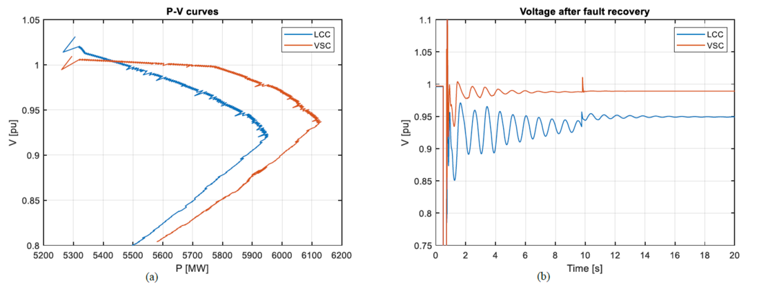
Figure 3.2 - Comparing LCC and VSC at the Châteauguay substation (a) P-V curves (b) Voltage after fault recovery
3.1.4. Islanded Modes of Operation
In 2020, Hydro-Québec examined the possibility of integrating a specific islanded mode of operation using the existing LCCs to mitigate the post-contingency spills at BHN resulting from the tripping of the MSC tie line. Limitations associated with LCC-HVDC technology, such as the stringent short-circuit current requirements, rendered the implementation of a stable islanded mode of operation unachievable. BHN’s inability for continuous secondary frequency regulation further hindered this strategy, which, if implemented, would have procured significant operational flexibility and achieved fast and reliable mitigation of BHN post-contingency spills. VSC-HVDC technology overcomes those limitations as it presents a number of advantages for islanded systems. Those advantages include reliable operations at low short-circuit current capacity, no commutation failure under AC disturbances, flexible controllability, continuous frequency regulation and voltage support of the islanded system, and blackstart capability. Accordingly, the new converters will enable the effective integration of BHNCHAT islanded modes of operation and therefore expand the scope of BHN-CHAT operations by addressing water management and resiliency concerns.
3.2. Increased Converter Capacity
The increased capacity of the new BtB VSCs would upgrade the total converter capacity of the HVDC station to 1,500 MW. In effect, the interconnection would be able to operate entirely asynchronously, reducing the number of radially connected BHN units in normal operating conditions. These units could instead be integrated into the local subsystem and supply local load or inject power back into the 735 kV system. The repurposing of the BHN-CHAT complex would optimize and simplify the operation of the BHN generating station by reducing the number of start and stop cycles, and thereby avoiding accelerated generator degradation [3]. Frequent switching of circuit breakers at the BHN 120 kV busbar, which diminishes breaker lifetime, would also be curtailed, avoiding costly premature breaker replacements.
3.3. New Substation Topology
The planned replacement of the HVDC converters provided an opportunity to reassess the operational capabilities and configuration of the entire substation and ensure that the new converters and substation design are in line with anticipated system needs and future usage. Incorporating the new converters into the existing substation, while maintaining uninterrupted operation of the BHN-CHAT complex, required a full-scale redesign of the substation’s topology. The redesign leverages the benefits of VSC-HVDC and repurposes some the substation’s key components in order to improve the flexibility and overall reliability of the substation and adjacent facilities.
Facilitated by the new HVDC connection scheme, the updated design makes efficient use of the current layout and incorporates the capability of directing generation from BHN collected at the 120 kV busbar to either the 735 kV side or the 765 kV side of the substation by using two of the 765/120 kV station’s existing transformers. This is achieved by modifying the transformers’ tap changers and primary side protection parameters, making it possible to connect the transformers at both primary voltage levels. Each transformer can be switched from one side to the other using a series of 735/765 kV breakers. On the low-voltage side of the transformers, the station’s 120 kV busbar can be configured so that groups of BHN units can by simultaneously synchronized to both systems, which considerably increases the number of possible operating configurations. This capability further improves reliability of the BHN-CHAT complex by providing additional electrical paths for BHN supplies. It also provides valuable operational flexibility and is particularly practical for the new operating modes discussed in section 4.
4. Islanded Modes: A New Operating Paradigm
The operational philosophy underpinning the development of the new islanded operating modes facilitated by the new VSCs incorporates resiliency and a water management mindset into the operational framework of the BHN-CHAT complex and the local regional subsystem. From a resiliency perspective, the objective of the new paradigm is to introduce hybrid solutions that combine infrastructure upgrades [4], such as the new HVDC converters and the substation reconfiguration, with innovative operating strategies so as to provide improved redundancy, robustness, and flexibility and hence significantly enhance the overall resilience of the local regional subsystem. From a water management perspective, the aim is to take full advantage of the technical attributes of VSC-HVDC in the development of operating strategies that go beyond traditional operating practices, using the transmission system to effectively optimize water management of the St. Lawrence River.
4.1. Existing Operational Challenges of the BHN-CHAT Complex
The continuity of power transmission of the BHN generating station output is critical for water level management of the St. Lawrence River. Continuous monitoring of upstream and downstream water levels is critical for safe maritime traffic along the BHN canal. This particularity influences the operating strategies of the BHN-CHAT complex since system contingencies and configurations can indirectly affect water levels. For example, the impact of tripping the MSC tie line is significant in terms of water spills as it results in an instantaneous rejection of all BHN units synchronized on the NYPA system at the time of the trip. In the event of a tie line trip, the BHN substation is reconfigured such that a maximum number of rejected units are promptly re-dispatched to the local subsystem by way of the adjacent BHN 120 kV lines. However, existing system constraints limit the number of units that can be redispatched, resulting in water spills from the forced tripping of a minimum of 4 units. Other mitigative actions require a manual reconfiguration of the Châteauguay substation, which is slow to deploy.
4.2. Reverse Mode of Operation
In this context, the reverse mode of operation (RMO) enabled by the BtB VSC-HVDC was introduced in the overall design to implement a prompt mitigative solution for post-contingency spills resulting from the loss of the MSC tie line. The RMO consists of operating the BHN units synchronized to the NYPA system prior to contingency in a load-less islanded configuration, radially connected to the 765 kV side of the converters. The active power generated by the islanded BHN units would be redirected to the HQ system through the BtB VSC link. This transition can be performed either automatically or manually. The automatic post-disturbance transition would be configured such that, upon the tripping of the MSC tie line, the converters at the 765 kV side will switch from active power control mode to the islanded control mode, while the other converters at the 735 kV side are operated in DC control mode. The 765 kV converters connected to the islanded BHN units would then be operated in voltage frequency regulation mode (droop control), which can dynamically adjust active power flow through the VSCs to control the frequency of the islanded system. The RMO can also be performed manually by utilizing the VSC’s blackstart capability and a preset series of system configurations. Figure 4.1 and Figure 4.2 illustrate two possible system configurations enabled by the RMO.
The RMO is a smart, cost effective and flexible operational solution that overcomes the drawbacks of existing mitigative actions and enhances water management resiliency of the BHN canal. It achieves dynamic post-contingency redispatching of BHN units, enabling the seamless automatic redirection of BHN power transfer to the HQ system, which would eliminate water spills and generation curtailment. Additionally, the RMO, combined with the new VSCs and the redesigned substation topology, provides an alternative higher capacity electrical path between the BHN complex and HQ’s system, overcoming short-circuit current constraints of the 735 kV side of the Châteauguay substation.
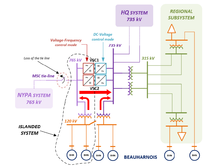
Figure 4.1 - RMO with one 765/120 kV transformer connecting some BHN units to the HQ system
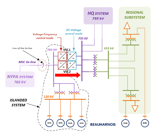
Figure 4.2 - RMO with the two 765/120 kV transformers connecting to the BHN island
4.3. Islanded Mode of Operation
The sudden loss of both 735 kV lines connecting the Châteauguay substation to Hydro-Québec’s main grid causes the formation of an islanded system comprised of BHN units and the regional subsystem load. The consequence of such an event is a drastic increase or decrease in the island’s frequency, influenced by the imbalance between BHN generation and local load, causing generator tripping.
In this context, an islanded mode of operation (IMO) was incorporated into the VSC design to simultaneously address operational, resiliency and water management concerns. The IMO consists of the dynamic or manual islanding of the regional subsystem upon the loss of 735 kV supply lines. The dynamic islanding mode would be initiated with a 50 ms worse case time delay from the opening of the 735 kV line breakers. The converters on the 735 kV side would be automatically set to the islanded control mode, with the converters at the opposite end being operated in DC control mode. The 735 kV-side converters would then be operated in voltage frequency regulation mode, dynamically adjusting the power transfer through the VSC to rapidly compensate for the mismatch between generation and load of the island local subsystem. Should the dynamic islanding fail, manual IMO can be performed to achieve fast restoration of the island. These converters would then be energized from the DC side and operate as a voltage source (islanded control mode) to blackstart and restore the island. This restoration process consists of a predefined step-by-step procedure that gradually connects local loads and BHN units to speed up the restorative recovery.
The IMO can be implemented utilizing three configurations of the Châteauguay 765/120 kV station, as illustrated in Figure 4.3 and Figure 4.4.
BHN units can be connected to the islanded regional system either via the 765/120 kV switched to the 735 kV side, or directly by way of existing 120 kV lines. Configurations with the most units connected to the island would increase the islanded system’s inertia, and hence improve the post-disturbance response of the dynamic IMO. To ensure the post-disturbance stability and the proper operation of the local island, a pre-disturbance reference connection scheme with a minimum number of BHN units may be required. This may be particularly relevant when we consider the time delay between the loss of the 735 kV link and the activation of the VSCs’ islanded mode. Inertia and the kinetic energy of BHN units can be used to compensate for the mismatch between generation and load.
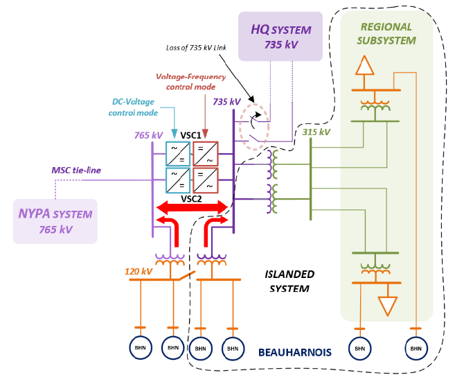
Figure 4.3 - Islanded m ode of o peration at 735 kV side with one 765/120 kV transformer connecting BHN units to the local island
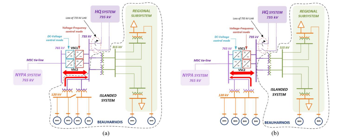
Figure 4.4 - Islanded mode of operation with (a) Châteauguay transformers connected to the local island and with (b) Châteauguay transformers connected to the NYPA system

4.4. Future Operational Planning of the IMO
Identifying all the operating configurations of the BHN-CHAT complex and its regional subsystems depends on several interdependent variables; they include daily and seasonal load profiles of the regional subsystem, power exchanges with the adjacent subsystems, configurations of the BHN generating station, equipment outages, and water management constraints. From a short-term operational planning perspective, this complexity can be simplified by capturing the dominant operating trends of the BHN-CHAT complex through empirical probabilistic distributions based on historical data.
Figure 4.5 (a) depicts the bivariate distribution of the regional subsystem load versus its BHN generation; it indicates that most of the time the regional load exceeds the radial BHN generation. Figure 4.5 (b) shows that 65% of the time this load-generation mismatch is between zero and 700 MW. However, this imbalance can be optimized as a larger portion of BHN generation can be made available to supply the regional subsystem load through the proposed substation reconfiguration and increased HVDC capacity.
To ensure optimal implementation of the IMO, the pre-disturbance mismatch between the islanded BHN generation and the local load should be monitored in operation to minimize the VSC post-disturbance power adjustment and ultimately avoid any potential power transfer inversion through the MSC tie line. Thus, a real time dispatching of BHN units to the regional subsystem would be easily performed by the operator to optimize the regional subsystem’s load imbalance with islanded BHN units.
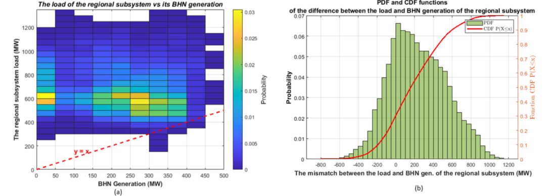
Figure 4.5 - (a) The bivariate distribution of the regional subsystem load versus its BHN generation and (b) the PDF/CDF of the mismatch between the load and BHN generation of the regional subsystem
4.5. Exploratory EMT Grid Forming Simulation of the IMO
Exploratory EMT simulations were performed to evaluate the dynamic stability and transient behavior of the IMO upon the loss of the 735 kV link, presuming grid forming (GFM) controls. A generic EMTP GFM [5] converter is used to represent the grid side of the VSC at the Châteauguay 735 kV busbar. The IMO was initially simulated with two GFM control strategies: droop-based control and virtual synchronous machine (VSM) control. The first step is to determine the parameters for each GFM control strategy and compare their performance based on a benchmark scenario. In a second phase, the droop-based control strategy was selected to simulate several operating configurations according to three different control schemes: (1) the VSC permanently operating in GFM control, (2) the VSC achieving a transition from grid following (GFL) to the GFM control upon the detection of the islanding, (3) the VSC achieving a transition from GFL to GFM and promptly changing the power order after detection of the island.
4.5.1. Network Setup
The EMT simulated network setup is presented in Figure 8. It included an average modeling of a single 840 MVA rated power GFM converter [5] that represents the 750 MW VSC pole at the Châteauguay 735 kV side. Its control system can be set to either the droop base control or the VSM control. The BHN generation is modeled with two types of aggregated synchronous generators along with all their relevant control systems: Type I BHN units equipped with a power system stabilizer (PSS) – PSS2B stabilizer, and type II BHN units without a PSS. At the remote end of each 735 kV line, the Hydro-Québec system was modeled by a Thevenin equivalent with the appropriate short-circuit power.
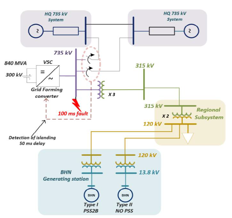
Figure 4.6 - BHN CHAT complex n etwork setup
4.5.2. Brief Overview of GFM Controls
The structure of the simulated GFM control strategies is based on [6, 7]. For the droop control (Figure 4.7), the transfer function defining the inverter angular frequency 𝑤𝑖𝑛𝑣 and the phase angle 𝜃𝑖𝑛𝑣 is expressed by:
(1)
Where 𝑤0 is the nominal angular frequency, 𝐾𝑤 is the frequency droop coefficient, 𝑃𝑟𝑒𝑓 is the reference output power, 𝑃𝑚 is the measured output power and 𝑇𝑐 is its filtering time constant. The reference voltage magnitude used for the inner voltage and current control (Figure 4.8) is defined by:

Figure 4.7 - Block diagram of the implemented droop base control
(2)
Where 𝑉0 is the nominal voltage magnitude, 𝐾𝑞 is the voltage droop gain, 𝑞𝑟𝑒𝑓 is the reference reactive magnitude, 𝑞𝑚 is the measured reactive power and 𝑇𝑐 is its filtering time constant.
For the VSM control mode (Figure 4.9), the angular frequency deviation is based on the swing equation, expressed in [7] as:

Figure 4.8 Block diagram of the implemented reactive power control
(3)
Where 𝐾𝑑 is the damping coefficient applied to the difference between 𝑤𝑖𝑛𝑣 and the grid frequency provided by a PLL. 𝑇𝑎 is the mechanical time constant corresponding to the virtual inertia (2H). The frequency droop coefficient, 𝐾𝑤, is included in (3) such that, in steady state, (3) reduces to (1) to represent the steady state behavior of the speed governor of a conventional SM. The VSM transfer function expressing the converter angular speed 𝑤𝑖𝑛𝑣 and its phase angle 𝜃𝑖𝑛𝑣 is derived from (3) such that:
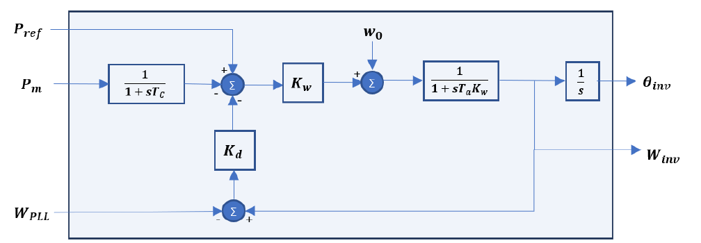
Figure 4.9 - Block diagram of the implemented VSM
(4)
From (4), the GFM parameters can be aggregated such that:
(5)
(1) to (5) shows that the GFM control strategies provide voltage and phase references for the cascaded inner voltage and current controllers, hence, allowing the converter to behave as a voltage source. The GFM power control provides the phase angle reference 𝜃𝑖𝑛𝑣 used for the 𝑑𝑞 transformation, while the GFM reactive power controller provides the voltage amplitude reference . The
reference is set to zero.
4.5.3. Simulation results
The simulated GFM parameters for the droop and VSM control strategies are presented in Table I. These parameters have been tuned via simulation to achieve a stable post-disturbance response, and to attain the desired steady state behavior. Setting the VSM damping coefficient to zero did not have a negative impact on the converter’s dynamic response and eliminated the dependence of the control to the PLL. Inertia time constant 𝑇𝑎=2𝐻 has been set to 6 s to emulate the inertia constant of a hydraulic generator (3 pu.s). The voltage droop coefficient 𝐾𝑞 have been set to a very small value (0.1%) for the converter to act as a stiff voltage source. The frequency droop coefficient 𝐾𝑤 is adjusted to 1% to achieve a very tight frequency control of the island. The droop coefficients of the droop base and the VSM controls are identical so that both strategies achieve the same steady state behavior.
| Parameters | Description | Droop-base | VSM | Units |
|---|---|---|---|---|
| Tc | P, Q filter time constant | 0.2 | 0.2 | s |
| Kw | Frequency droop coefficient | 0.01 | 0.01 | pu |
| Damping coefficient | 0 | 0 | pu | |
| Ta = 2H | Inertia time constant | 0 | 6 | s |
| Kq | Voltage droop coefficient | 0.001 | 0.001 | pu |
The droop and the VSM controls were compared by simulating the benchmark illustrated in Table II. At 𝑡=5 𝑠, a 100 𝑚𝑠 bolted three phase fault is applied at the 735 kV bus followed by the tripping of the two 735 kV lines.
| Scenario ID | PAC VSC (MW) | BHN Type I (Nb. of units) | BHN Type II (Nb. of units) | Total BHN Gen. (MW) | local LOAD (MW) | 735 kV link pre-disturbance injected power (MW) |
|---|---|---|---|---|---|---|
| A0 | 756 | 3 | 1 | 195 | 400 | -551 |
The simulation results pertaining to this event (Figure 4-10) shows that both GFM controls naturally adjust the active power output through the phase angle reference 𝜃𝑖𝑛𝑣 to compensate for the loss of the 735 kV link and ensure a stable dynamic response. The post-disturbance response of the active power and the 735 kV voltage of the droop base and VSM controls are almost identical. The frequency of the droop control reaches its steady state almost instantly following the fault clearing. The VSM frequency shows a slow response time because of the effect of the inertia time constant.
The scenarios presented in Table III have been simulated with the GFM droop base control. The effects of the transition from GFL to the GFM control and the change of the active power reference upon the detection of the islanding have been evaluated for different configurations. A 50 ms delay for the detection of the islanding after the fault clearing has been considered. A non-seamless transition from the GFL to GFM control has been assumed.
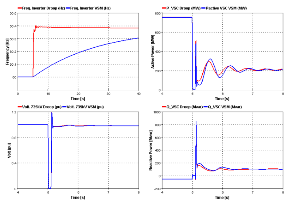
Figure 4.10 - Droop and VSM comparison Application of 100 ms three phase fault followed
by the tripping of the 735 kV link
Simulation results for the A1, B1 and C1 scenarios, with nine type I and one type II BHN units, are presented in Figure 4-11. The results show that operating permanently in GFM is more effective and ensures a higher performance than performing a transition from GFL to GFM control upon the detection of the islanding. The change of the VSC power reference to rapidly eliminate the load-generation mismatch is not effective as it amplifies the local mode electromechanical oscillations of the BHN units. The GFM droop control rapidly stabilizes the frequency at 60.57 Hz. Therefore, initiating an automatic 𝑃𝑟𝑒𝑓 change would not be recommended. In scenarios A1, B1 and C1, 90% of BHN units connected to the island are equipped with a PSS, so the local mode oscillations of 1.5 Hz are rapidly damped.
| Case ID | PAC VSC (MW) | BHN Type I (Nb. of units) | BHN Type II (Nb. of units) | Total BHN Gen. (MW) | local LOAD (MW) | 735 kV link pre-disturbance injected power (MW) |
|---|---|---|---|---|---|---|
| A1;B1;C1 | 756 | 9 | 1 | 465 | 400 | -821 |
| A3;B3;C3 | 756 | 1 | 9 | 585 | 400 | -941 |
| A4;B4;C4 | 756 | 0 | 0 | 0 | 400 | -356 |
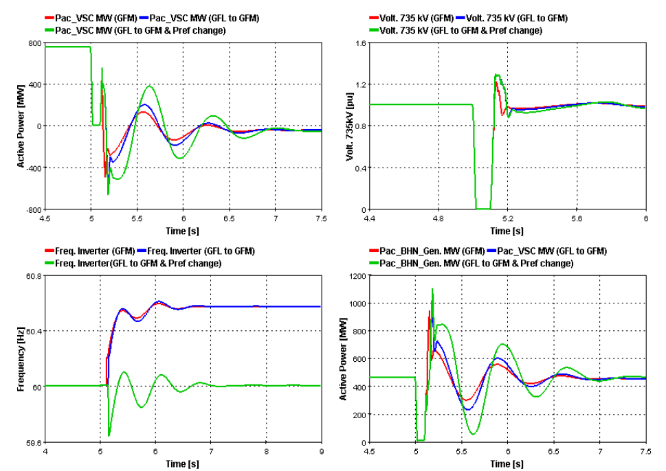
Figure 4 11 - Simulation results for A1, B1, C1 9 type I and 1 type II BHN units
Figure 4.12 illustrates the results of the islanding without any BHN generating units. The GFM droop control achieves fast, effective post-disturbance responses that rapidly attain the steady state. The transition from GFL to GFM causes high active power and voltage overshoots since significant reactive power is injected into the system by the VSC. The local mode oscillations are not observed because none of the BNH generating units are connected to the island.
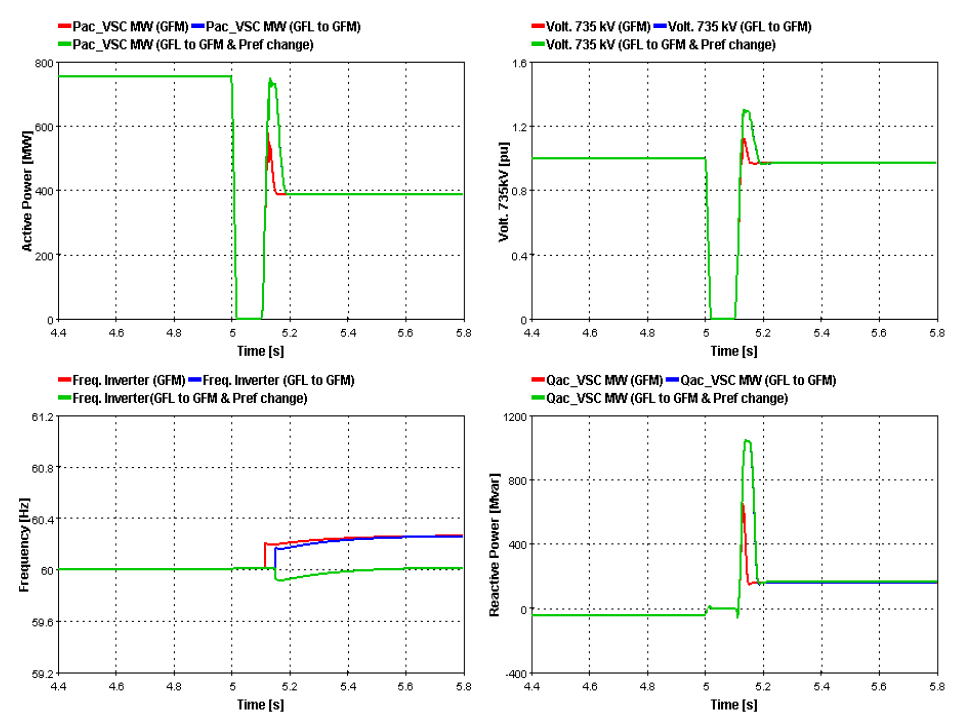
Figure 4.12 - Simulation results for A4, B4, C4 no BHN units connected to the island
The simulation results of the islanding of the local subsystem with nine BHN units of type II and one BHN unit of type I are presented in Figure 4.13. The results show that operating with a high number of types II BHN units causes significant post disturbance local mode oscillations of 1.57 Hz. Even though the electromechanical oscillations of the BHN units were slowly damped, the GFM droop control maintained the stability of the island. The transition from GFL to GFM causes the tripping of the VSC by the overvoltage protection. The observed over-voltages are particularly significant when the 𝑃𝑟𝑒𝑓 is rapidly adjusted upon the detection of the islanding. In fact, the 𝑃𝑟𝑒𝑓 change generates a significant and sustained reactive power injection causing prolonged over-voltages.
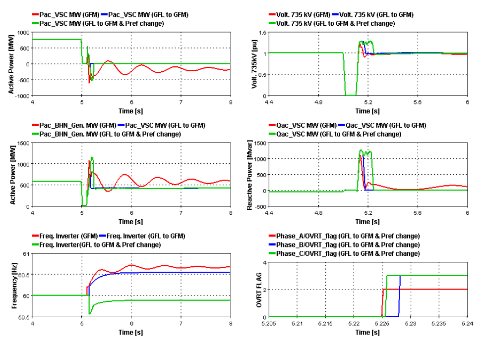
Figure 4.13 - Simulation results for A3, B3, C3 1 type I and 9 type II BHN units
From a system performance perspective, the simulation results show it is more effective to permanently operate the VSC in GFM control, whether in grid connected or islanded mode. However, care should be taken in tuning the GFM parameters to achieve robust performance in all system configurations. Performing a control transition from GFL to GFM mode upon islanding detection depends on external signals and requires the implementation of a seamless control transition. Additionally, a proper design and tuning of the P-Q priority control function are required to adequately limit the post-disturbance reactive power injection. Lastly, the operation with a significant proportion of type II BHN units amplifies the post-disturbance electromechanical oscillations and reduces their damping. The integration of a Power Oscillation Damper (POD) with the GFM control would be effective in achieving a fast damping of these local mode oscillations. This aspect will be further investigated in future work.
5. Conclusion
The paper presented a comprehensive discussion of the technical factors considered in Hydro-Québec’s decision to replace the aging BtB HVDC converters at its Châteauguay substation with two new BtB VSC-HVDC. By outlining the technical and economic advantages of VSCs, the paper demonstrated that, despite being less commonly utilized for BtB configurations, VSC-HVDC technology proved to be the most suitable option for the new converters, in light of the technical particularities of the Châteauguay substation and its adjacent systems. In particular, the reactive power capability of VSCs is especially practical for the bulk grid, as VSC-HVDC can provide valuable voltage support and mimic the functionality of SVCs. In terms of voltage stability, dynamic simulations demonstrated that VSC-HVDC outperforms LCC-HVDC in this respect, providing greater power oscillation damping by regulating the 735 kV bus voltage, which improved transient stability.
The paper presented a redesigned substation topology that leverages the full capacity of VSC functionality and supports the development of new operating modes that enhance resiliency and water management. It discussed how the successful integration of the new RMO and IMO would enhance the BHN-CHAT complex’s ability to optimize water management of the St. Lawrence River. Both modes offer significant operational flexibility and resiliency by promptly forming functional islanded microgrids supported by the VSCs, which help minimize post-contingency spills.
The transient stability of the IMO on the Châteauguay 735 kV side was also explored from a system performance perspective. The integration of two GFM control strategies, the droop base control and the VSM control, were explored and compared through EMT simulations. The GFM droop base control was selected for an in-depth exploratory assessment of the IMO, considering various BHN-CHAT configurations. Different droop base control schemes were simulated: VSC exclusively operated in GFM droop base control, VSC initiating a transition from GFL to GFM control upon the detection of islanded operation, and a variant of the second that combines rapid active power reference change. The results demonstrated the effectiveness of operating the VSC exclusively in GFM droop base control mode, as it achieves the best post-disturbance performance during a severe islanding event. Implementing a control transition from GFL to GFM mode would be complex and less effective. Operating the IMO with an increasing number of type II BHN units would amplify the 1.5 Hz electromechanical oscillations and further reduce the damping. The integration of a POD with the GFM control would be an effective solution to further increase damping, and hence, operate with a variable number of type II BHN units without any restriction. Future work will be performed for an effective integration of the POD prior to the commissioning of the new converters.
References
- P. Le-Huy, A. Abdellaoui, K. Gauthier and H. Akremi, “Châteauguay Interconnection SVC Refurbishment: Real-Time Hardware-in-the-Loop Commissioning Study Experience,” International Conference on Power Systems Transients, 17-20 June 2019.
- N. G. Hingorani and L. Gyugyi, "Static Shunt Compensators: SVC and STATCOM," Understanding FACTS: Concepts and Technology of Flexible AC Transmission Systems, IEEE, pp. 135-207, 2000.
- O. Savin, C. Badina, J. Drommi, J. Baroth, S. Charbonnier and C. Bérenguer, “Influence of Starts and Stops on the Aging of Hydroelectric Generator Stators by Thermal Cycling:,” ESREL 2021 - 31st European Safety and Reliability, pp. 3214-3221, 21 Septembre 2021.
- R. M. e. al., "From Reliability to Resilience: Planning the Grid Against the Extremes," IEEE Power and Energy Magazine, vol. 18, no. 4, pp. 41-53, 2020.
- H. Ashourian and H. Gras, “GFM Inverter,” EMTP-EMTPWorks, 2023.
- S. D’Arco, J. Suul and O. Fosso, "A virtual synchronous machine implementation for distributed control of power converters in smartgrids," Electric Power Systems Research, vol. 122, p. 180 – 197, 2015.
- B. Johnson, G. Roberts, A. D. D.-G. O. Ajala, D. Ramasubramanian, A. Tuohy, D. Divan and B. Kroposki, “Generic Primary-control Model for Grid-forming Inverters: Towards Interoperable Operation & Control,” in Proceedings of the 55th Hawaii International Conference on System Sciences, Hawaii, 2022.

