A Case Study of Protection of an LV Microgrid
Author
Ray BROWN - RBPE, Australia

Summary
A microgrid is an electrical system, with defined boundaries and which includes distributed energy resources (DER), that is able to change between grid-connected and islanded modes of operation. While there are a range of generation sources that could be used within a microgrid, one implementation that is becoming increasingly common at low voltage (LV) is for the microgrid to be built around a battery energy storage system (BESS), with rooftop photovoltaic (PV) systems included to generate electricity.
The use of inverter-based resources can give rise to a number of issues for the electrical protection of the microgrid, the main one being the large difference in fault levels between grid-connected and islanded modes of operation. Another issue is that there can often be bidirectional power flows within the microgrid, rather than power always flowing in the one direction. A number of schemes have been proposed to overcome such issues but these can be expensive and difficult to implement in small systems.
This paper describes a case study of the protection implemented in a low voltage, AC microgrid in Australia. The microgrid is at Narara, north of Sydney, and was commissioned in September 2021. It consists of a 270 kW / 437 kWh BESS, over 350 kW of rooftop PV and a 70 kVA standby generator.
In determining an appropriate protection system it was necessary to consider what criteria the system needed to meet. This included whether it was necessary for the system to achieve full selectivity when operating in islanded mode. Fault levels within the system, both in grid-connected and islanded mode, were calculated. The response of the BESS in islanded mode to a fault needed to be understood, including the maximum current output and the duration for which it could be supplied. A grading study was carried out to determine settings for the LV circuit breakers within the system. Conclusions about the applicability of standard overcurrent protection in such microgrids are made.
The paper also touches on other protection implemented in the microgrid, including loss-of-mains (LOM) protection used to trigger the change from grid-connected to islanded mode in the event of a loss of the normal supply, and the use of zone-selective interlocking (ZSI, also referred to as a blocking scheme) for improved safety of personnel in the event of an internal arcing fault in the LV main switchboard.
Keywords
BESS, Low voltage, Microgrid, Islanded operation, Overcurrent, Loss-of-mains protection, Zone selective interlocking1. Introduction
A microgrid is a segment of an electricity distribution network that contains load and distributed generation and/or storage - collectively, distributed energy resources (DER) - that is able to disconnect from the electricity grid and operate independently. This independent operation is referred to as islanded operation or islanded mode, as the disconnected part of the electricity network is thought of as an electrical "island". The obvious advantage of such a microgrid is that it can supply electricity when the main grid is out of service for any reason. This might be because of damage from natural events (storms, floods, fires, etc.) or human activity (car hit pole, strikes to underground cables, etc.), equipment failures or during maintenance.
The DER within the microgrid in this case study comprises a battery energy storage system (BESS) and rooftop photovoltaic (PV) systems on houses and community facilities. The BESS serves as the core of the microgrid, setting the voltage and frequency reference when in islanded mode. While BESSs and PV systems are expected to be popular choices for use within microgrids, other generation and storage types could be used, such as diesel generators, gas engines, gas turbines, wind turbines, micro-hydro, biomass, fuel cells, compressed air energy storage, etc.
2. Technical Challenges of Microgrids
2.1. Fault Levels
One of the main technical challenges with microgrids is that the fault level when operating in islanded mode can be considerably less than when grid-tied. A BESS would typically be able to provide a maximum fault current of twice its nominal rated current. The fault current able to be provided by the grid depends greatly on the actual installation but a typical figure might be 10 times the rated supply capacity and possibly significantly higher. This difference in fault current means that overcurrent protection that is designed for the normal grid supply may not work as intended when operating in islanded mode.
2.2. Reverse Fault Current Flow
If the generation within a microgrid is connected at a different point to the normal supply, the fault current flow could be in the opposite direction through some elements. For example, if a BESS were connected to a downstream switchboard then fault current would flow toward the main switchboard when in islanded mode, rather than away from the main switchboard when in grid-tied mode.
3. Options for Protection of Low Voltage Microgrids
There are a wide variety of microgrid protection schemes proposed in the literature to overcome the issues discussed above. In addition to standard overcurrent, protection types that have been suggested include:
- directional overcurrent and directional earth fault;
- negative sequence overcurrent;
- voltage-controlled overcurrent;
- differential protection;
- distance protection;
- adaptive relay settings;
- central protection;
- direct transfer trip (DTT);
- phasor measurement units (PMUs) and micro phasor measurement units (µPMUs).
Many of the suggested protection schemes are more applicable for sub-transmission and transmission systems than for low voltage distribution networks. LV networks tend to have many branches, rather than being point-to-point as is more common at higher voltages. In many cases the cost of more advanced relays is simply not justified, particularly where large numbers are required. Some novel protection schemes discussed in the literature as being especially suitable for microgrids are only at the research stage and are not commercially available. Given these factors, there are in practice few protection types beyond standard overcurrent protection that are viable for use in LV microgrids.
4. Protection Selectivity Criteria
One of the primary concerns in the literature about protection of microgrids is that, in islanded operation, the BESS (or other generation) will not provide sufficient fault current to ensure overcurrent protection operates as intended, resulting in the BESS tripping and the entire microgrid being de-energised rather than just the particular faulted item of equipment or cable. That is, protection selectivity - the ability to isolate only the faulted section and maintain the rest of the electrical system intact - is not achieved. This is often seen to be a major concern.
However, there is a strong argument that lack of protection selectivity in microgrids is not, in many cases, an important issue. The first point to note is that, unless there is some local regulation or some niche reason to operate otherwise, microgrids will normally run in grid-tied mode and only change to islanded operation when the grid is lost. Operating in grid-tied mode has a number of advantages, including that the grid can supply any shortfall or absorb any excess of generation. For a microgrid normally operated in grid-tied mode, operation in islanded mode will be rare and hence the period of time during which fault levels are reduced is short. This time period will obviously depend on the particular microgrid and the grid from which it is supplied but would typically fall within the range of a few hours per year to a few days per year. For there to be an issue with protection selectivity there also has to be a fault within the microgrid while it is in islanded mode. That is, there has to be two faults, one in the external network and one within the microgrid. The probability of such a double contingency is much lower than the probability of a single fault. For example, if both the external grid and the microgrid were each out of service for 1% of the time (3.65 days per year), which would generally be a low level of reliability, the average length of time during which they were both out of service could be approximately calculated as 0.01 x 0.01 x 365 days per year, or about 53 minutes. Thus, the likelihood of the situation arising where there was a fault while operating at reduced faults levels is low.
The second point to make is that, as discussed later in this paper, not all faults in a microgrid operating in islanded mode will cause selectivity issues. Faults deeper in the network may well be cleared by the protection without any problem. It is faults higher up in the network that can cause issues.
The third point is that if there is a fault and the protection does not operate as designed and the BESS (or other generation) trips off on overload and the entire microgrid is lost, the fault is still cleared. It is not elegant and it will probably be more difficult to locate the fault but the danger to people and equipment has been removed.
Thus, the problem with a lack of protection selectivity in microgrids seems overstated, as both the likelihood is low (two separate faults, with the fault in the microgrid having to be in the "right" location) and the consequences are low (the fault would be cleared by the BESS tripping out). If there were no microgrid, supply would have been lost for the first (grid) outage, so it is difficult to see that having a microgrid in any way makes the supply reliability worse.
One aspect that should be checked with regard to the BESS (or other generation) tripping to clear a fault is to make sure it can not automatically reclose and re-energise the fault. The method of tripping should also be determined, whether it is a circuit breaker opening or simply just the power electronics of the converter shutting down. If the latter, it may be necessary to check for compliance with local regulations, although it may well be the case that such a circumstance is not envisaged in the applicable regulations.
5. Narara Ecovillage Microgrid
5.1. Background
Narara Ecovillage is a new residential community located about 55 km north of Sydney, Australia. It is being developed in three stages on the site of a former agricultural institute and will eventually include up to 150 homes. Construction of houses commenced in 2018 and the first residents moved in in 2019. Residents of the village are members of a co-operative that owns the community facilities and that is developing the site to be an environmentally, socially and economically sustainable community [1].
As at January 2025, 55 houses have been built with six more under construction. As part of the building standards for the village, each residence must be fitted with a PV system that generates more energy through the year than the consumption of the residence. At present approximately 368 kW of rooftop PV is installed, with approximately 30 kW installed on community buildings and the balance distributed across houses in the village. It is expected that the total installed PV capacity will increase over time to roughly 1 MW.
5.2. Electrical System
The site is a high voltage electricity customer, with supply at 11 kV from the local distribution network services provider (DNSP) to a private 1000 kVA distribution substation on-site. The substation is of the padmount (or kiosk) type and incorporates a 1000 kVA transformer fitted with an on-load tap-changer (OLTC), believed to be the first such distribution transformer installed in Australia. The substation supplies a private LV network, which in turn supplies the various residences and community facilities on the site via an underground cable network. There is a 70 kVA standby diesel generator installed in the LV network at a location remote from the main switchboard. It is used during extended outages when insufficient power is available from the PV systems. Figure 1 shows a simplified single line diagram of the system.
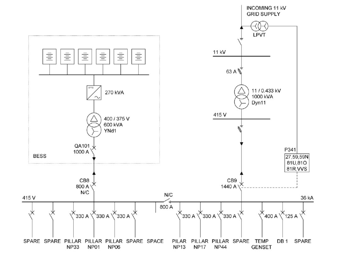
Figure 1 - Simplified single line diagram of the Narara Ecovillage microgrid
5.3. Battery Energy Storage System
A 270 kVA / 437 kWh battery energy storage system (BESS) was installed at the site and commissioned in September 2021. There were three main purposes for installing the BESS:
- reducing the carbon footprint of the village by storing renewable energy generated on-site for overnight use, thus reducing the importation from the grid of electricity generated from non-renewable sources;
- providing power to the site during grid outages;
- producing income through energy arbitrage, frequency control services, etc.
The site has suffered from a low level of reliability of the grid supply and has experienced a number of long power interruptions over the last decade, one power outage being 14 days in duration due to a major weather event. The BESS, in conjunction with the distributed energy resources (PV) and the standby generator, is intended to power essential loads during such grid outages. The BESS forms the basis of the microgrid for the site. It is able to operate in both grid-tied and islanded mode. In grid-tied mode it is configured to minimise the active and reactive power drawn from the grid, charging using the excess power generated by the PV systems during the day and discharging during the evening and night. In the event of an outage of the grid supply to the site, the loss-of-mains (anti-islanding) protection detects the outage and opens the main 400 V circuit breaker (CB9) on the incomer to the LV main switchboard. The BESS then changes modes and becomes the frequency and voltage reference for the site.
When the microgrid is in islanded mode the PV systems still generate power. This extends the length of time the system can operate before fully discharging the battery. Indeed, during an incident in November 2021 when an equipment issue with the distribution substation meant that grid supply could not be used, the combination of the BESS and the rooftop PV was able to maintain supply to the entire site for very nearly a full week, even during overcast and rainy weather. That this was able to be achieved was due to a number of factors, including: the excellent energy efficiency of the residences built at the Ecovillage; the relatively mild temperatures at the time; the fact that village had in place a mature messaging application through which they were able to request community members to reduce power consumption; and that the BESS system was sized to serve a future, larger number of residences than had been constructed to that date.
6. Narara Microgrid Protection Scheme
6.1. Protection Types
The main protection used within the Narara Ecovillage microgrid is standard overcurrent protection, utilising moulded-case circuit breakers (MCCBs), fuses and miniature circuit breakers (MCBs), see Section 7.
Loss-of-mains (LOM) protection is used to determine when to change from grid-tied to islanded mode, see Section 8.
Check synchronisation protection is used to ensure the microgrid is synchronised with the external network when returning to grid-tied operation from islanded mode, refer Section 9.1
Zone selective interlocking (ZSI) is implemented on the LV main switchboard to give faster clearing in the event of an internal switchboard fault, see Section 9.2.
6.2. Fault Levels
The fault current that can be provided by the BESS alone in islanded mode depends somewhat on the loading of the BESS before the fault but is nominally a maximum of twice its normal rated current (for 2 s), or about 0.84 kA. The BESS can supply lower overload currents for longer times, e.g. 140% normal rated current for five minutes.
The three-phase fault level at the LV main switchboard of the Narara microgrid when grid-tied is calculated as 18.7 kA, neglecting any contribution from PV or the BESS. The fault current that can be supplied (at the main switchboard) when grid-tied is thus more than 20 times that which can be supplied when the microgrid is islanded (ignoring any contribution from PV).
It should be noted that the fault current from the grid will decrease with increasing cable length away from the main switchboard. The fault level at the most distant distribution pillar in the village is calculated as 1.5 kA.
6.3. Reverse Fault Current Flow
For the Narara Ecovillage microgrid, the BESS is connected at the same (main) switchboard as the normal supply, see Figure 1. This means that for a fault anywhere within the microgrid, the fault current always flows in the same direction, from the main switchboard to the fault. This greatly simplifies the analysis of the protection scheme.
7. Overcurrent Protection
7.1. Protection Settings
Settings for the various overcurrent protective devices in the microgrid were computed in the normal way, assuming supply from the grid and hence "normal" fault levels. The time-current curves for the various protective devices are shown in Figure 2. There is generally good, but not perfect, grading - with the few instances of malgrading considered acceptable.
There are two main types of infrastructure that are required to be protected when the microgrid is in islanded mode. The first requirement is to clear faults within electrical installations, in this case primarily the houses within the Ecovillage but also including a small number of community facilities. The second is to clear faults on the main LV cabling across the site. In Stage 1 there are six outgoing LV feeders from the main switchboard, which feed 42 LV pillars (NP, "network pillars", on Figure 1). These LV feeders are primarily 0.6/1 kV, 240 mm² aluminium conductor, XLPE insulated, four-core cables.
7.2. BESS Fault Capability
The overload capability of the BESS, as discussed in Section 6.2, is that it is effectively able to supply a maximum of twice normal current for 2 s. This is taken as 844 A.
It is understood that a fault with a sufficiently low impedance that would otherwise result in a fault current of more than 844 A will cause the BESS to shut down. This is different from some inverters, that will try to maintain the maximum fault current but reduce their output voltage. In this case it means that the supply to the entire microgrid would be lost.
The total impedance from the BESS to the fault location is thus a critical factor in determining how the BESS responds to a fault. The total impedance is that of the cables from the BESS to the location of the fault plus the fault impedance. The total impedance will increase the deeper the fault is located within the microgrid, given the greater cable lengths and smaller cable sizes used in circuits within residences. If this total impedance is less than approximately 0.27 Ω (230 V / 844 A) then the BESS will trip out for the fault. It should be noted that this impedance figure is only approximate, as the fault current able to be provided by the BESS will depend on its pre-fault power loading. The BESS overload capability curve is Curve (5) in Figure 2.
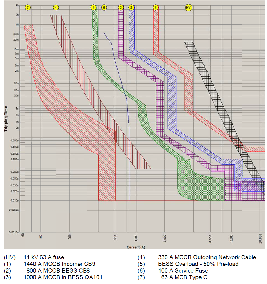
Figure 2 - Protection time-current curves and BESS overload curve
7.3. Faults Within Installations
Electrical installations of residences and community facilities will generally have three layers of protective devices. The first is an 80 A or 100 A service fuse on the supply to the premises. The second is a miniature circuit breaker (MCB) functioning as the main switch for the premises. These are typically 63 A. The third layer is the MCBs used to protect sub-circuits, such as a 20 A MCB for a general power circuit within a house.
It is possible, for a fault at specific locations on the installation's switchboard, that only one or two protective devices "see" the fault. Indeed, for a fault on the incoming terminals of the service fuses, none of these protective devices will see the fault and it will need to be cleared by the MCCB at the main switchboard protecting the network cable. However, the vast majority of electrical faults within residences will be seen by at least one and most probably three protective devices. The 100 A service fuse is shown as Curve (6) on Figure 2 and the 63 A MCB is shown as Curve (7). MCBs for sub-circuits are not shown but would be to the left of Curve (7).
It can be seen from Figure 2 that all three layers of protection will clear a fault of up to 844 A well within the 2 s overload time of the BESS. A 100 A service fuse grades below the over-load characteristic of the BESS for all fault currents up to 844 A. At 844 A, the fuse will operate in a time of 0.2 to 0.9 s (allowable time-current zone in AS 60269.3.1), giving a grading margin of greater than 1 s to the BESS overload characteristic.
Similarly, a 63 A Type C MCB will grade under the BESS overload characteristic for all currents up to 844 A. Indeed, it will trip on magnetic operation (no intentional delay, taken as a nominal tripping time of 10 ms) at a current of 5 to 10 times rated current, i.e. 315 to 630 A. Similarly, the smaller MCBs on individual final circuits will also grade under the BESS overload characteristic and will trip on "magnetic" at fault currents well below 844 A. For example, a 20 A Type C MCB typically used to protect a power circuit would trip "instantaneously" at a current between 100 and 200 A.
7.4. Type of MCB Used Within Installations
Miniature circuit breakers are available with different instantaneous (magnetic) tripping characteristics. Type C MCBs, which are the most common type in Australia for general applications, including domestic installations, have an instantaneous trip characteristic of between 5 and 10 times the MCB rated current. Type B MCBs, which are used for general applications in a number of other countries, have an instantaneous trip characteristic of 3 to 5 times rated current.
The use of Type B MCBs, with their lower instantaneous trip values, may have advantages in LV microgrids where selectivity is an issue. While not a problem in this case study, in some instances the much faster tripping in the 5 to 10 times current range may mean that the tripping curve moves under the BESS overload characteristic and thus selectivity is achieved. This would be achieved with no increased complexity of the protection system. However, Type B MCBs may be more expensive in some markets than Type C, particularly for the lower fault rating MCBs (≤ 6 kA) generally used in domestic premises.
7.5. Faults on LV Distributors
Faults on the LV network cabling or in the network pillars will need to be cleared by the MCCBs in the LV main switchboard. These MCCBs are set with a long-time current pick-up of 330 A and are Curve (4) in Figure 2.
As discussed in Section 6.2, in grid-tied mode the three-phase fault levels on the main LV network cables vary from more than 18 kA at the main switchboard down to about 1.5 kA at the most distant LV distribution pillar. This is well above the fault current capability of the BESS of 0.84 kA and it is thus expected for almost all faults on these cables that the BESS will simply shut down. This can be seen in Figure 2 where the BESS overload capability, Curve (5) dark blue, intersects with the MCCB protecting the LV network cables, Curve (4) green, at a current of about 750 A.
The MCCBs will grade correctly with the BESS in islanded mode for overloads and for (rare) high-impedance faults where the fault impedance restricts the fault current to below 750 A.
7.6. Overcurrent Protection Summary
In islanded mode, it is considered that for faults within installations the protective devices will most likely clear the fault before the BESS shuts down, with selectivity thus being achieved. For faults on the main LV network cabling and in network pillars, it is considered unlikely that the fault will be cleared by the upstream breaker in the main switchboard before the BESS shuts down and hence supply to the entire village would be lost.
8. Loss-of-Mains Protection
8.1. Protection Types Used
Loss-of-mains (LOM) protection is not one particular type of protection but rather a set of protection functions used to detect when grid supply is lost and hence when the microgrid should transition to islanded mode [2]. Another name for loss-of-mains protection is anti-islanding protection but, as the whole point of the microgrid is to (intentionally) form an island, the term "anti-islanding" makes little sense in this application.
The protection functions incorporated in the Narara microgrid for LOM protection are:
- undervoltage (ANSI 27)
- overvoltage (ANSI 59);
- neutral voltage displacement (residual overvoltage, ANSI 59N);
- under-frequency (ANSI 81U);
- over-frequency (ANSI 81O);
- rate of change of frequency (ROCOF, ANSI 81R);
- voltage vector shift.
The LOM protection was implemented using a commercial protection relay that included all the required protection functions. It monitors the voltage on the 11 kV side of the 1000 kVA supply transformer via a low power voltage transformer (LPVT) complying to IEC 60044-7. The relay was connected to the 11 kV supply rather than at 400 V as it was a requirement of the local utility to implement neutral voltage displacement (NVD) protection to detect an earth fault on a disconnected (and hence unearthed) section of their 11 kV network. NVD protection needs to take its voltage input from the 11 kV side of the transformer, as the delta-star (Dy) winding connection of the 1000 kVA supply transformer "decouples" the LV side from the zero-sequence voltages on the 11 kV side that are the basis for NVD protection.
The microgrid is normally configured to automatically return to grid-tied mode when the grid supply is restored after an outage, although it can be set to stay islanded until a manual change-back is initiated. The reason for automatically returning to grid-tied mode is to avoid situations where, for example, operators have to be called out at 3:00 a.m. after a fault because the BESS is about to be fully discharged. The return of mains is detected by the LOM protection relay when all LOM protection elements clear, meaning that voltage and frequency are within their normal ranges. If this is maintained for 60 s the relay issues a signal to the control system to return to grid supply.
8.2. LOM Protection Sensitivity
The experience with the LOM protection in transitioning from grid-tied to islanded mode in the event of an outage of the grid supply is that it operates sufficiently quickly that the interruption is seen by the end users as a "voltage dip" rather than an "outage". This is highly desirable, as it minimises impacts on the end users. Anecdotal evidence is that voltage vector shift is the element that most commonly initiates the transition to islanded mode. This makes sense, as the setting used of 8° is quite sensitive and there is no intentional time delay. It is estimated that by January 2025 the microgrid had experienced 15 grid outages and consequent transitions to islanded operation since it was commissioned. The transitions both to and from islanded mode have proven robust, with effectively no interruption of supply.
In microgrids such as Narara Ecovillage, where it is possible to achieve effective no-break transfer from grid-tied to islanded mode and the end users do not experience an outage, it makes sense to set the LOM protection as sensitive as possible. If there is an actual outage of the grid supply then it gives a fast transfer to islanded mode. If it is a disturbance rather than an outage then nothing is lost, as the end users do not see an interruption (nor on return to gird-tied mode). This is not the case for microgrids where, for whatever reason, it is necessary to have an outage when transferring to islanded mode. In that case it makes sense to set the LOM protection to be slower, so that it does not operate for a disturbance.
9. Other Protection
9.1. Check Synchronisation
When the microgrid is in islanded mode and then grid supply is restored there is a no-break return to grid-tied mode. That is, there is no interruption in supply to the microgrid during the transition. This is done by the BESS control system synchronising the BESS to the grid supply and then closing circuit breaker CB9 to parallel the two systems and return to normal grid supply. The two supplies should only be paralleled if the frequency, phase and voltage of the two networks are the same to within a certain tolerance (synchronisation window).
While the BESS incorporates internal protection against inadvertent unsynchronised paralleling with the grid, an external check synchronisation (ANSI Device No. 25) function was included as an additional safeguard. The LOM protection relay selected has check synchronisation capability, so this could be implemented at no additional cost. The LOM relay already had a three-phase voltage input from the LPVT on the 11 kV side of the supply transformer, so this was used to monitor the grid supply for check synchronisation. The relay has a second, single-phase voltage input that is used to monitor the low voltage (400 V) BESS supply. The relay incorporates settings to compensate for the 30° phase shift between the HV and LV windings (Dy11) of the 1000 kVA supply transformer. However, it was necessary to incorporate an interposing voltage transformer on the LV voltage input to the LOM relay, as the relay model used could not directly connect a voltage as high as 400 V phase-phase.
The check synchronisation settings adopted are given in Table 1. The voltage window is somewhat wider than preferred, to allow for the fact that the 1000 kVA supply transformer is fitted with an on-load tap-changer (OLTC) that has a tapping range of ±5%. As the check synchronisation element was connected to the 11 kV side of transformer, the grid voltage on the LV side (the voltage of interest for synchronisation) was not a fixed ratio of the HV voltage and could differ from it in relative terms by ±5%. A wider voltage setting had to be adopted to account for this.
| Parameter | Value |
|---|---|
Phase angle | ±10° |
Frequency | ±0.1 Hz |
Voltage | ±7.9% |
9.2. Zone-Selective Interlocking
Zone selective interlocking (ZSI), sometimes also known as a blocking scheme, was implemented on the LV main switchboard to give fast clearance of internal switchboard faults when in grid-tied mode. ZSI is discussed in IEC TR 61912-2 with a number of examples [3]. It works by simple signalling between the downstream outgoing circuit breakers and the upstream incoming circuit breaker (CB9). If any downstream breaker detects a fault, meaning that the fault is on an outgoing circuit, it outputs a signal onto a common signalling bus. This restraint signal is received by the upstream circuit breaker and it operates in accordance with its normal protection settings. These setting are chosen to include a delay to allow the downstream breaker to trip and clear the fault. The scheme thus "blocks" (restrains) the fast operation of the upstream breaker if a downstream breaker has sensed a fault current.
If the upstream breaker CB9 detects a fault current but does not receive a restraint signal from a downstream breaker, it means that the fault is within the switchboard itself. In this case CB9 trips with no intentional time delay, thus clearing the fault much more quickly. This minimises the damage to the switchboard and reduces the arc flash hazard to anyone who might be in the switchroom at the time of the fault. Overall it can decrease fault clearing times while maintaining both selectivity between circuit breakers and also backup protection in case of a circuit breaker failure.
One of the great advantages of ZSI is that it can be cheap and easy to implement if all of the circuit breakers on the switchboard are from the one manufacturer, which would typically be the case. A number of manufacturers offer ZSI capability in their product ranges. Signalling wiring between circuit breakers uses twisted pair cable with cross-section typically of 0.4 - 2.5 mm². In this case, all signalling wiring was within the one switchboard and hence was straightforward to install.
While faults within LV switchboards are rare they can have serious consequences. Zone selective interlocking can reduce clearance times for such faults at low cost.
10. Conclusions
A number of conclusions regarding protection in LV microgrids can be drawn from the experience gained with the Narara Ecovillage microgrid.
- Reduced fault currents when operating in islanded mode, resulting in loss of protection selectivity, are often described in the literature as a major problem. However, in many LV microgrids the circumstances giving rise to such issues (a double contingency and the fault within the microgrid being in specific locations) will be very rare and the consequences minor.
- Normal overcurrent protection using standard LV switchgear can give satisfactory protection performance in LV microgrids.
- More sophisticated protection schemes, as described in the literature, are generally prohibitively expensive or not commercially available.
- Designing the LV microgrid so that the largest generator (e.g. a BESS) is connected at the same switchboard as the normal grid supply means fault currents flow in the same direction through the microgrid network in both grid-tied and islanded modes, simplifying protection considerations.
- Understanding how a BESS responds to a fault is important in understanding the protection performance of a microgrid but this information can sometimes be difficult to obtain.
- The use of Type B instead of Type C miniature circuit breakers (MCBs) could improve selectivity in some circumstances, at no increased complexity.
- Standard loss-of-mains protection can operate fast enough to give effective no-break transfer (no interruption perceived by end users) from grid-tied to islanded mode.
- Zone selective interlocking (ZSI) can be a cost-effective method of reducing clearing times for internal faults in LV switchboards, helping to reduce damage to the switchboard and arc flash hazard to personnel.
References
- D. Stephens, R. Brown & S. Elphick, "A Practical Method for Control of PV Generation in Microgrids", CIGRE 2022 Kyoto Symposium
- Ray Brown, "Loss-of-Mains Protection for DER in Australia", CIGRE 2025 Trondheim Symposium
- International Electrotechnical Commission Technical Report IEC/TR 61912-2 "Low-voltage switchgear and controlgear - Over-current protective devices - Part 2: Selectivity under over-current conditions"