Tyrrhenian Link and Adriatic Link – Harmonized Converter Stations for Italian Underwater HVDC Connections
Authors
Marco CORTESE, Francesca PEDE, Mattia DERIU - Terna Rete, Italia
Volker HUSSENNETHER, Markus LEHMANN, Torsten PRIEBE, Christian KRIEGER, Roberto SANDANO - Siemens Energy, Germany

Summary
In Italy, the electricity system is advancing, in accordance with the challenging objectives set in the National Integrated Energy and Climate Plan (“PNIEC”) and the targets in the EU’s Green Deal, which aim to cut at least 55% greenhouse gas emissions by 2030. In addition to facilitating development and integration of renewable sources, the construction of the HVDC lines Tyrrhenian Link East and West connecting Campania, Sicily and Sardinia regions and Adriatic Link connecting Marche and Abruzzo regions will resolve grid congestion, boosting transmission capacity between the various market areas and improving quality of service.
The links are constructed using VSC half-bridge converters, high voltage DC cables and sea electrodes for the neutral return path. On the AC side the converter stations are connected to Italian 400 kV AC system. This paper outlines various aspects of the converter station design, control and protection system features, system planning, commissioning sequence and future network extensions in Italy.
Main topic is the discussion of a harmonized design which is chosen for all six converter stations of the three HVDC links. The technical requirements are analysed with special focus on Italian stringent environmental conditions to elaborate benefits and boundaries of common choice of HVDC equipment. Furthermore, for converter station layouts concepts using fixed building blocks are discussed enabling the adjustment to site specific topographies.
For Control and Protection C&P a country specific implementation of Human Machine Interface HMI is followed. Using identical C&P hardware for the three projects allows common development of software with flexibility towards different commissioning stages which are defined by the stagewise availability of HVDC cables. Based on common requirements of the AC networks to which HVDC schemes will be connected a joint approach to C&P studies is discussed.
As part of the Italian national strategy for energy transition and decarbonization, Tyrrhenian Link and Adriatic Link together with the HyperGrid project, represent a fundamental step toward modernizing and strengthening the transmission network, enabling a more efficient integration of renewable energy sources while ensuring system stability and security.
Keywords
Commissioning, Control and Protection System, Converter Station Design, Environmental Aspects, Expandability, HVDC, System Planning, VSC1. Introduction
The three individual projects are bidirectional point-to-point bipolar HVDC transmissions systems interconnecting HV AC systems. The Tyrrhenian Link East interconnects the main land substation Eboli to the substation in Sicily Termini Imerese. Tyrrhenian Link West is also connected to Termini Imerese heading to substation Selargius in Sardinia [1]. The Adriatic Link Interconnector is connecting the substation of Fano with the substation of Cepagatti.
Each DC system is realized as a bipolar system with sea electrodes. Using the electrodes it is possible to remain in monopolar operation with sea return if one HVDC cable is damaged. For a failure of the electrode or associated electrode line the bipolar topology allows for monopolar operation with metallic return using the HV pole conductor as neutral return path. In addition to the monopolar and bipolar operation which can be obtained by the HVDC system, the topology offers the possibility of STATCOM operation to provide voltage support to the network even for cases when the HVDC cables are not in service. Appropriate DC and AC switchgear enable the change-over between the individual operating modes of the bipolar HVDC system without power interruption.
The high degree of similarity with regard to the electrical requirements makes the three projects presented here very suitable choices for a harmonized design approach. The concept of a harmonized design refers to an approach wherein the components, functionality, and overall design are standardized to meet the most stringent requirements across all stations or links within a given system. This unified design strategy is adopted to ensure maximum compatibility and performance consistency throughout the systems.
Advantages of this approach include a lean methodology with respect to engineering, design, and testing phases. By utilizing a harmonized design, the process becomes more streamlined as the need for customized solutions for each station or link is eliminated. This results in a more efficient engineering cycle, reduced complexity in design, and a simplified testing regime due to the uniformity of the system components.
However, a potential downside to the harmonized design approach is the acceptance of equipment that may be partially overdesigned for certain applications within the system. This ensures that the equipment will meet the demands of the most challenging conditions present in any given link or station.
2. Harmonized Design of Converter Stations
2.1. Overview of Requirements and Characteristics
A simplified single line diagram of one bipolar system is provided in Figure 1. Table 2-1 summarizes the general characteristics of the three projects. Each HVDC scheme comprises:
- AC circuit breakers for fast fault clearing and reconfigurations.
- Each pole of the HVDC has a separate cable feeder to the nearby AC substation. In case of Tyrrhenian Link an AC transfer bus is foreseen in addition to allow monopolar or bipolar operation via one AC feeder when the other is out of service.
- DC switchgear for quick reconfigurations of the HVDC without power interruption comprising the earth return transfer switch (ERTS) and the metallic return transfer switch (MRTS), as well the neutral bus grounding switch (NBGS) and the neutral bus switch (NBS).
- Dedicated cable discharge resistors, which are required to create a defined voltage state of the DC cables during the reconfiguration sequences, are installed at the high voltage terminals of the converter stations. The resistors are used specifically to limit discharge stresses acting on the HVDC cables as compared to direct grounding.
- DC transfer switch to enable monopolar operation of the converters with the HV cable of the other converter pole, i.e. HVDC converter pole 1 with the HV cable of pole 2 and vice versa.
- Converter reactors placed on the DC terminals of each converter arm to limit high di/dt fault currents for faults at the DC terminals of the converter.
- Each converter station is connected to an own dedicated sea electrode. For Tyrrhenian Link the two converter stations of East and West bipole in Sicily Termini Imerese are equipped to use either the own sea electrode or in case of maintenance or outage of the own sea electrode to be connected via a neutral interlink to use the electrode of the other bipole.
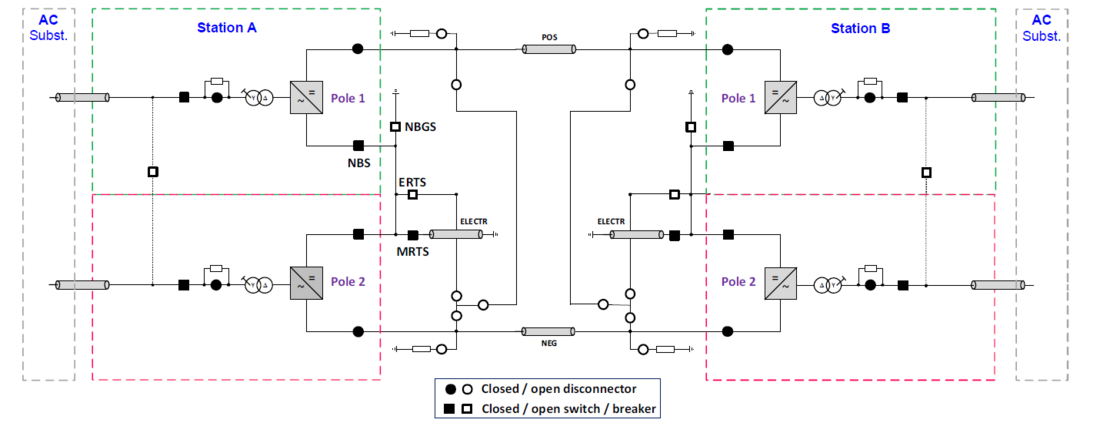
Figure 1 – Simplified Single Line Diagram with switchgear configured for bipolar operation
| Tyrrhenian Link East Link | Tyrrhenian Link West Link | Adriatic Link | |
|---|---|---|---|
| Converter Stations | Eboli, Termini Imerese | Termini Imerese, Selargius | Fano, Cepagatti |
| System topology | Bipole with HVDC cables and sea electrodes | ||
| DC cable length (approx.) DC cable technology | 510 km MIND | 520 km MIND | 250 km Extruded |
| Operating configurations | Bipolar, Monopolar Sea Return, Monopolar HV Return, STATCOM | ||
| Transmission Power | 2 x 500 MW at rectifier DC terminals, bi-directional | ||
| Reactive Power | 2 x ±225 Mvar at converter AC terminals (minimum requirement) | ||
| Nominal DC voltage | ±500 kV | ||
| AC system nominal voltage | 400 kV | ||
| AC connection | AC cable, AIS switchgear | ||
| AC Filter | Not necessary | Not necessary | pending |
| Converter topology | VSC, Multi-Level, Half-Bridge, 4.5 kV IGBTs | ||
| Converter Transformer | 3 phase – 2 winding transformers, YNd, 582MVA | ||
| Control modes | P/Q mode + U/f mode for system restoration | ||
2.2. Harmonized Design Requirements
This section is to outline motivation and implications of harmonized design of HVDC converter stations during design phase. Special considerations are required in case at later stage a subsequent HVDC project is identified to be covered by an already established harmonized design. For the projects covered by this publication the 4 converter stations of Tyrrhenian East and Tyrrhenian West are the initial projects for which the harmonized design was established in 2022. The two stations of Adriatic Link were identified as subsequent project to be covered by the harmonized design in 2023.
As initial step of a design phase for harmonized converter stations the known specific requirements of the different HVDC schemes need to be analysed. Given the identical ratings as shown in section 2.1 high similarities in design of all converter stations are expected. Furthermore, the harmonized design is motivated since all links are supplied for Italian TSO with uniform country specific standards. Thus, key decisions for harmonized design of converter stations are defined by local conditions of the individual converter stations as follows:
- Seismic stresses: the harmonized design is motivated for switchgear, measurement and C&P hardware by a universal safe shut down criteria of 0.5 g required to bring the HVDC link out of service under any seismic events. For remaining equipment within the converter stations the maximum peak-to-ground acceleration of 0.3 g of all stations is followed whereas the minimum requirement of all stations is 0.1 g.
- Site pollution severity: For Mediterranean coastal regions the site pollution is characterized by high salinity content. Following profound analysis in Italy including regional mapping a maximum pollution level of 112 g/l (“heavy” to “very heavy” according to IEC 60815-1) is defined. Minimum requirement of all stations is 80 g/l (“heavy”). One critical item within the harmonized design for equipment is the non-consistent combination of maximum values of seismic stresses and pollution levels. The feasibility of exposing long insulators with high creepage values to seismic stresses was carefully evaluated together with equipment manufacturers during the development of the harmonized design.
- For indoor environment uniform reduced salinity levels are defined following appropriate selection of air filtering class.
- Maximum ambient temperatures: A uniform maximum ambient temperature of 45 °C is selected of all HVDC equipment. Since for Adriatic Link maximum ambient temperature is limited to 40 °C converter cooling system and HVA/C equipment are designed for 40 °C.
- Minimum ambient temperatures: Only converter station Eboli of Tyrrhenian East requires ambient temperature slightly below 0°C of -3.5°C. Thus, for Eboli the converter cooling system, is equipped with an anti-freezing option to cover unlikely scenario of no-flow of cooling water during outage of the HVDC scheme at low temperatures.
- Audible noise: Local implementation of the converter stations need to be considered following the official acoustic zoning as defined in Italy. Within the harmonized design all converter stations follow an identical basic acoustic design derived for Tyrrhenian Link. More stringent audible noise requirements were met Adriatic Link as follows: in Fano noise protection walls secure emission levels at the station boundary. In Cepagatti improving the acoustic design by e.g. selecting lownoise outdoor coolers contributed to meeting noise audible levels at nearby dwelling houses.
- AC harmonic performance: despite choosing a harmonized design of the converter station naturally the AC harmonic performance of each site will depend on local background levels and local harmonic network impedances. To enable possible implementation of passive AC filters during detailed design an adequate headroom is foreseen in the inductive reactive power of the HVDC converter station to assure meeting reactive power limits.
2.3. Harmonized Design of HVDC Main Equipment
A harmonized main component design of the HVDC proves advantageous especially when it comes to type and special testing. By generating a common base of the component design by establishing a harmonized design only one set of type and special test is required. Based on limited availability of special testing facilities (e.g. for salt fog tests of insulators) a harmonized component qualification constitutes a major time conservation aspect for each individual project.
Furthermore, for later operation the harmonized design eases inherently maintenance activities by allowing uniform planning of maintenance activities and lesser training efforts of personal. For Termini Imerese converter stations of Tyrrhenian East and Tyrrhenian West with interchangeable equipment are directly adjacent to each other enabling economic savings by providing common spare parts.
Table 2-2 summarizes the main components and comments the respective design ideas with regards to the harmonized design.
| Component | Harmonized design | Main design criteria related to harmonized design / comment |
|---|---|---|
| Converter | Yes | Most demanding P and Q requirements Highest transient stresses (e.g. most demanding short circuit powers of network) |
| Converter water Cooling system | Partially | Highest heat dissipation of all converters, Local ambient temperature |
| Transformer | Yes | Most demanding P and Q requirements Highest ambient temperature of all stations Most demanding logistic restrictions (mass and dimensions) |
| Converter arm reactors | Yes | Most demanding P and Q requirements Highest transient stresses |
| DC high speed switches | No | Harmonized design would have been possible. Updated manufacturing towards EU F-Gas regulation caused a change in the design between the projects from SF6 to Clean Air solution. |
| AC breaker | Yes | Highest short circuit power of the network |
| Pre-charge resistor | Yes | Highest energy dissipation during start-up |
| DC cable discharge resistor | Yes | Highest energy dissipation during DC cable discharge |
| AC filters (optional) | No | Harmonized design not feasible due to different AC harmonic impedances/ background harmonics |
2.4. Harmonized Layout of HVDC Converter Stations
Figure 2 shows converter station Termini Imerese of Tyrrhenian East Link with common features of the harmonized design as introduced in sections 2.1 to 2.3. In this section two key areas are discussed with respect to their relevance of layouts of the converter stations:
- Building arrangement from the AC terminals of the converter up to the DC cables and control building as shown with green boundary in Figure 2:
To protect especially all HVDC equipment from harsh environment indoor solution is chosen for all high voltage areas. The arrangement comprises converter halls, DC halls as well as control building and outdoor DC neutral area located between the converter poles. For all sites of the harmonized design the entire area is a firm building block within the layout with universal defined interfaces.
- Outdoor AC yard and converter transformer area as shown with yellow boundaries in Figure 2:
As shown in Figure 2 for Termini Imerese the arrangement allows integration of the AC buscoupler between the incoming AC feeders. Furthermore, the parallel orientation of AC feeders towards the converter enables integration of a “ready-to-connect” solution of the converter transformers for which upon a converter transformer outage the spare transformer may be connected via gantries to the affected pole. The connection to the gantries is done manually by flexible droppers and is considered as effective solution shortening outage time since it eliminates need of transformer movement.
However, in case of Selargius and especially Cepagatti the layouts were adapted addressing hilly site topologies. The changed arrangement of the AC feeders and converter transformers for Cepagatti is illustrated by the dashed yellow arrows in Figure 2. The range of this flexible arrangement is illustrated by comparing the change of station footprint from approximately 270 x 210 m² for Termini Imerese to approximately 450 x 120 m² for Cepagatti. Thus, rearranging the AC feeder and converter transformer area allowed to adjust the aspect ratio of the stations from 270/210 = 1.3 to 450/120 = 3.8. Still, it is to be noticed that feature of AC buscoupler and “ready-to-connect” solution of the spare converter transformers are not incorporated for the stretched arrangement in Cepagatti.
The above discussion shows how incoming AC feeders and arrangement of converter transformers are used for fitting the converter station on different converter station sites while maintaining a fixed arrangement of main buildings.
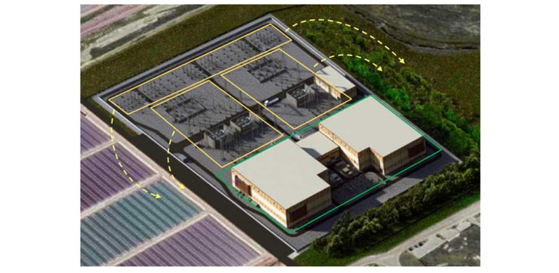
Figure 2 – Converter Station Termini Imerese of Tyrrhenian East Link with layout arrangement for harmonized design approach: firm building block within green envelope. Flexible arrangement of AC feeders and converter transformer area in yellow.
3. C&P Solution and Functionality
Peculiarity of Italian HVDC projects is to demand for high availability of each plant or their different parts, please refer to chapter 2.1 for further details. The combination of high availability with the use of the sea electrodes as return conductors results in a flexible and robust MMC bipoles including design practise from earlier Line Commutated Converter LCC solutions. Many rigid bipolar MMC schemes have been seen in the recent past, hence these bipolar schemes with harmonized design deserve attention from numerous control & protection (C&P) points of views, as we will try to see below.
3.1. Overview of C&P Requirements
The Italian TSO has been used to associate a defined State to each system configuration creating a sort of State Machine on both the local and the remote human machine interface (HMI). These common C&P definitions apply whether an LCC or a VSC scheme is adopted, no matter which supplier is implementing the solution. The harmonized solution for the control structure is then not confined to the under development MMC bipoles but follow an historical developed design. This strategy naturally simplifies the Owner´s operations and maintenance, however, various Contractors need to adopt to re-design established concepts normally requiring supplemental effort.
Nowadays, most of HVDC converter stations are required for unmanned operations and in this context a Remote Terminal Unit (RTU) is placed in the HVDC control building. In this way the remote operation is handled in a similar manner to every other HVDC in the Italian AC network.
Despite Sicily and Sardinia being islands, 400 kV lines are present, guaranteeing quite robust SCL in normal network configurations. This allows grid following controls to be always used, except in restoration scenario or very weak network. Apart the standard active power control, it is worth to mention the AC Line Emulation Control for Tyrrhenian East and Adriatic Link: As the name suggests, the transmitted power is as a function of the difference of the angles as measured at the AC nodes of each converter station [2].In the case of Tyrrhenian Link, the vicinity of the converter stations in Termini Imerese allows direct interfacing of control and protection systems of both bipoles. The optical fibre connection allows fast exchanging signals as required for Dispatching Centre´s needs.
3.2. Harmonized Design of C&P
Tyrrhenian Link combines two bipoles that from the control and protection perspective can be considered nearly identical. As such, the set of cubicles that will be delivered to the 4 sites may be seen as replicas. This gives the opportunity to decouple hardware (HW) and software (SW) preparation and testing. It is often the case, that a very critical milestone for the C&P is to ship the cubicles to either site or platform after a SW Factory Acceptance Test (FAT). Therefore, the SW finalization is normally requested to precede the shipment of the C&P HW. However, a large amount of site/platform activities related to the C&P HW do not require a finalized SW. The last portion of activities in preparing the SW normally deal with dynamic performance evaluation, such as tuning of network frequency regulators. The same is not seen as a pre-requisite to connect a zero-flux CT to the measurement panel. Consequently, using the synergies given by the two bipoles, the C&P HW of Tyrrhenian can be shipped to site as soon as the HW FAT and few other preliminary tests are achieved. This decoupling mechanism was here forced by the combination of the four DC cables availability as discussed in section 4 but effectively represents a pioneer strategy that could be taken by the numerous “convoy” HVDC projects elsewhere.
3.3. Harmonized C&P Studies
Studies to be performed during the execution phase [3] include e.g. dynamic performance study, blackstart study, subsynchronous torsional interaction study, transient stability study, harmonic stability study.
The HVDC converters are embedded in different parts of the Italian AC system. Therefore, it is required to investigate the dynamic and transient behaviour of the HVDC controls considering the different converter stations AC system topologies and conditions. That may also result in individual parameterization of control loops, such as AC frequency or AC voltage control functions.
There are certain aspects fostering a harmonized and common C&P studies approach for the mentioned HVDC projects:
- Common technical definitions of:
- Minimum short-circuit ratio for stable operation and fault-ride through
- Reactive power and AC voltage control functions
- Common EMT and phasor domain simulation tools
- Common C&P software base
- Common methodology in each study
The dynamic performance study covers also the investigation of stable operation and successful fault-ride through in grid following mode for a weak AC system condition. The lowest short-circuit ratio SCR is common for all three projects and can be handled as base parameterization and conservative scenario.
Individual AC system short-circuit level conditions are then considered complementary to further evaluate and adapt the base parameterization. This is also reflected in the different load flow conditions provided for the project, as well as in the combined Tyrrhenian Link East and Tyrrhenian Link West simulations.
Also, the demonstration of the black start capability can be harmonized between the projects. A generic AC system testing environment based on the Sicily network is used. It is considered as conservative approach for the black start capability demonstration. Its methodology and results are also applicable to the other converter stations.
With this approach, the fundamental parameterization of the C&P software for both the normal P/Q mode and the U/f mode for system restoration is achieved.
In addition to that, the individual aspects of the AC systems need to be considered in the subsynchronous torsional interaction study, the transient stability study, and the harmonic stability study.
4. Planning of Commissioning
The availability of the DC cables drives the commissioning activities in Tyrrhenian Link. The First stage of Tyrrhenian Link East is feasible because a single DC cable is laid. Afterwards Tyrrhenian Link West bipole will be commissioned. Only then, the second cable of Tyrrhenian Link East will allow the completion of East bipole. This commissioning structure allows the serialization of site activities optimizing supply chain and manpower. In this context, the Adriatic Link commissioning, placed after finalization of Tyrrhenian Link, can take advantages of all the lessons learnt gained within the previous experiences.
5. HyperGrid project
5.1. Overview of HyperGrid
In accordance with a holistic vision of the Italian National Electricity System, the HyperGrid interventions begin with the objective of creating synergy with the development works already planned in the previous Development Plans and with the existing infrastructure. The new layer in DC integrates in the best possible way with the existing and planned works, in order to achieve the maximum efficiency of the system, making use of the existing grid assets and avoiding construction of new infrastructure, optimising where possible and pursuing maximisation of Net Transfer Capacity (NTC) between market zones [4], [5].
In particular, the significant investments for the electricity transmission grids to benefit the national system will serve to increase the meshing and reliability of the network, to strengthen the backbones between the South (where the production of electricity from renewable sources is greater) and the North (where demand for electricity is more sustained), to enhance connections between the islands and the mainland together with Tyrrhenian Link and the Adriatic Link, to develop infrastructures on the two largest islands, and to improve the resilience, efficiency, sustainability and integration of renewables.
The timeline for the authorisation and implementation of the works in the context of the rapidly evolving energy generation and demand scenarios will be crucial. In this regard, the Italian TSO will adopt a modular approach to develop a flexible investment model that will allow the development of new grid infrastructure that reflects the actual energy scenario.
HyperGrid includes the conversion of existing alternating current (AC) transmission lines into direct current (DC) corridors and the construction of new HVDC links, including subsea connections. These upgrades will support the gradual transition toward a high-renewable penetration system while minimizing environmental impact through the repurposing of decommissioned sites and existing infrastructure.
5.2. Integration with Tyrrhenian Link and Adriatic Link
HyperGrid is conceived as a backbone system that integrates with ongoing strategic HVDC projects, such as the Tyrrhenian Link and Adriatic Link. These projects already play a crucial role in enhancing the interconnectivity between mainland Italy, Sicily, and Sardinia. Integration of these links within HyperGrid will reinforce the transmission network, providing additional capacity and operational resilience.
References
- F. Del Pizzo et al.; Tyrrhenian Link a paramount project to achieve the decarbonization of the Italian power system; Cigre Study Committee B4 Meeting, Paper 10778; 2022.
- P. L. Francos et al.; INELFE Europe's first integrated onshore HVDC interconnection; IEEE Power and Energy Society General Meeting, p. 1-8, ISSN 1932-5517; 2012.
- Guide for electromagnetic transient studies involving VSC converters, CIGRE TB 832 2021.
- Terna s.p.a, Allegato evoluzione rinnovabile e interventi di connessione, 2023. [PianoSviluppo].
- Terna s.p.A, Progetto Hypergrid e necessità di sviluppo, 2023. [ProgettoHypergrid].