Implementation, Field Operation and Standardization Consideration for Use of Mobile Battery Energy Storage in Temporary Power Applications
Authors
Farid Katiraei, Aghil Davari - Innoversa, Canada
Naera Haghnazarian, Ayman Lpizra, Kenneth Rice, Jennifer Hebsch - Eversource Energy, USA
Philip Johnson - Sunbelt Rental, USA
Damir Novosel - Quanta Technology, USA

Summary
Driven by reliability and resiliency use cases and in line with focus on decarbonization and sustainable development, Eversource Energy has embarked on a journey to deploy emerging non-wires alternative (NWA) to gain firsthand experience in operation, and to enhance the standards and procedures associated with use of emerging technologies such as Mobile Battery Energy Storage Systems (MBESS). Over the last 2 years, this unique NWA solution has been field evaluated through several pilot projects as an alternative method to replace and/or reduce the use of emergency/portable diesel genset across their service territory.
This paper presents results and observations from field deployment of multiple MBESS based on real-world evaluation of NWA use cases involving temporary powering of customer facilities for scheduled maintenance, planned extended outages, and seasonal peak load management. The paper outlines the best practice guidelines and standardization related to logistical aspects of owning, maintaining and operating MBESS.
Keywords
Energy Storage, Mobile, Temporary Power, Scheduled Outage, NWA, Seasonal Load1. Introduction
MBESS is normally discussed in contrast to stationary energy storage systems – with a key differentiator that MBESS is not locked into one physical location [1]. Therefore, it can significantly improve the business case for utilizing them as NWA applications that are temporary in nature, due to the specific characteristics of a power system event, or customer needs in a season, or during maintenance. In addition, in contrast to portable diesel/gas generators that may have been used for those temporary load and/or grid support cases, MBESS provides a cleaner, quieter, and much more versatile, and efficient solution.
Equipped with a power electronic converter for the energy conversion and interconnection to the electric grid, MBESS units can support diverse load type and grid conditions – including grid interactive operation or completely off-grid, standalone islanded operation.
The use cases for MBESS supports flexibility, reliability, and electrification efforts across various industry sectors. Its ability to provide rapid deployment, supporting emergencies, and managing seasonal peak load conditions makes the solution an invaluable asset for modern energy systems [2].
The modular design, scalability in the core platform and ongoing standardization efforts further enhance MBESS appeal and practicality [3]. MBESS units are designed to be easily transportable and scalable – by paralleling multiple units, allowing for flexible deployment to achieve several MW power ratings, and many MWH energy capacity. The modular approach also allows for phase-by-phase investments, aligning with load growth and seasonal demands.
2. Use cases
The major MBESS use cases can be categorized in several areas, including:
- Area 1: Resiliency and reliability enhancement by avoiding outage and/or fast recovery and supporting system restoration due to major weather events. Example of applications are:
- Providing backup power supply for critical customers and life-dependent facilities, such as emergency centres, shelters, gas stations and similar, during safety related power shut down for avoiding wildfire or impact of flooding and similar events.
- Performing black start services for grid energization to supply customers while storm recovery is taking place or for scheduled outage as part of routine system maintenance, such as transformers or cable replacement.
- Area 2: Seasonal peak load management to avoid distribution system overloading and potential outage. The key applications are:
- Remote areas of a utility service territory that do not have enough infrastructure to supply seasonal increase in load caused by tourism and growing vocational visitors.
- Frequent exposure to extreme hot/cold weathers influenced by climate change that puts stress on distribution assets and harder to predict the patterns.
- Area 3: Transmission & Distribution (T&D) upgrade deferral driven by introduction of new loads associated with electrification and decarbonization, to manage long lead time, supply chain delays, and project execution time. Examples are:
- Temporary grid support during the system development or upgrades,
- Infrastructure support for expanding electric vehicle (EV) charging stations, while construction of stationary systems are underway.
- Flexible charging in areas with limited EV chargers and/or distribution assets limitations for adding new chargers (e.g., when waiting for a service transformer replacement to support adding more EV chargers).
- Additional EV charging for events and gathering (weekend festivals and/or occasional events), when there is surge of customers.
MBESS is also well suited for applications that involve:
- Load variability with large difference between peak and minimum load conditions, that can severely reduce efficiency of conventional gensets and have adverse impact on operation during low load duration (below 30%).
- Requirements for low noise and emission in urban areas.
The ability to relocate MBESS to target areas downstream of a faulted circuit and/or a congested section of the line is shown in the figure 1 below. Any distributed energy resource (DER) such as solar PV plus energy storage that is connected upstream of the location of troubled segment of the line would not be able to help in this case, whereas the mobile energy storage can be installed at a customer site or connected to a pole-mounted transformer to supply downstream loads.
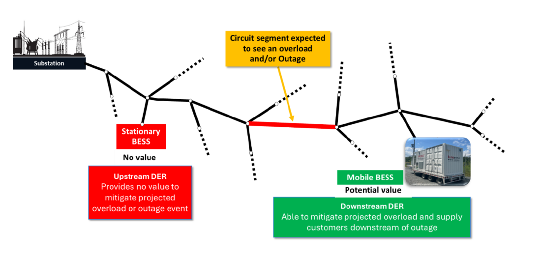
Figure 1 – Value Stream – Mobile Energy Storage
3. Implementation and Operation
The process diagram in Figure 2 illustrates major steps involving the deployment and utilization of MBESS for a pre-specified use case in given location. Aside from initial planning and before
getting to the operation, the heavy burden of the process is logistical aspects of transporting the unit to the pre-specified location, securing the unit at the site – typically with the use of temporary fencing – and safely interconnecting to the utility grid or a genset for power exchange with the grid and supplying customer facilities.
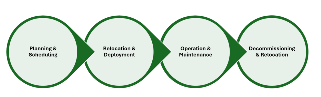
Figure 2 – Value Stream – Mobile Energy Storage
Step 1. Planning
- Determine Location: Identify deployment site considerations based on local access (roads and transportation challenges), demand, grid constraints, or emergency needs.
- Determine Timeframe of Deployment: Establish project timelines, including deployment and operational windows.
- Identify Stakeholders: Engage department within the utility (such as distribution planning, substation engineering, field operation, and standard groups). The deployment may require engagement with local authorities (such as local fire department and municipalities and town centres, and/or community members.
Step 2. Deployment
- Schedule Transportation and Logistics: Plan the movement of mobile units to the designated site.
- Coordinate Deployment: Align resources and personnel for setup. Determine temporary fencing and securing the access to the site.
- Interconnection: Ensure proper integration with the local grid, genset or microgrid resource.
- Inspection and commissioning: Assess the unit health condition and integrity of the system prior to energization. Verify the system settings and/or any configurations for the new site. Perform basic unit testing of safety and readiness.
Step 3. Operation and Maintenance
- Energization: Power up the system safely.
- Verification: Conduct testing and validation to ensure functionality.
- Operation: Begin active use, including monitoring and maintenance.
Step 4. Decommissioning
- System Shutdown and Disconnection: Safely power down the mobile energy storage system and disconnect it from the grid or local infrastructure.
- Site Restoration and Reporting: Restore the deployment site to its original condition and document performance, lessons learned, and any maintenance needs for future redeployments.
- Relocation: transport the MBESS back to the base (service centre) for storing and properly maintaining for the next deployment.
4. Pilot Projects
This section provides an overview of two distinctive pilot projects – among others - that were implemented by the utility in the first year after deployment of mobile units. Pilot 1 was a use case for supporting a planned outage event for a scheduled maintenance that required power supply for an extended period – about 8 weeks. Pilot 2 was a deployment at one of the utility’s service centres for capturing excess solar PV production in the daytime and shifting the energy toward the evening peak time (from 5 pm to 7 pm), since the peak of PV production does not match the utility demand peak. Both use cases are considered temporary (e.g. extended outage) or seasonal (such as excess PV production, which is primarily during summertime).
A key point to emphasize is that several departments within the utility were involved in different aspects of the pilot projects realization. The existing standards and field deployment procedure were documented and primarily followed up to the best of knowledge that would apply to the new technology.
4.1. Pilot 1 – Mobile Energy Storage for Extended Outages
Figure 3 and Figure 4 show pictures of one of the deployment projects in the field to provide 24/7 load supply during about 8 weeks of repair work on the upstream service connection. When a service transformer failure supplying a customer facility was identified by the filed crew, the distribution engineering determined that the best line of action is to completely replace the transformer and, at the same time, convert a part of overhead service line to underground cables for powering up the service station. However, this action would require an extended outage to the customer facility (a business complex) during the busy end-of the year season.
The conventional way to implement such an extended outage is to utilize multiple diesel gensets (e.g. two units for primary and backup units) and operate them 24/7 continuously. Although the approach has been well known, the short comings are: logistics of fuel delivery on a daily basis, noise associated with genset running during business hours, and need for having at least one person always on site to attend the cases of genset tripping, transfer or restart. To the businesses and customers visiting the complex, the key annoying aspects would have been the extensive noise and the smell of smoke in the air.
The implemented solution was pairing a mobile energy storage and genset, properly sized to supply the entire load during the working hours of the business complex. Hence, the genset operation for re-charging of the MBESS was delayed to later hours in the evening – after business hours. In addition, MBESS could better fit the variable load profile of the load – specially as the after-hour loads are drastically lower than the load in business hours. Low loading on reciprocating genset increases the fuel consumption and results in carbon built up in the engine – increasing the frequency of routine maintenance and adversely impacting wear and tear of the genset for a shorter effective life of the assets.
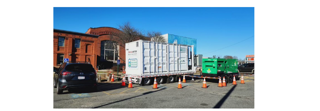
Figure 3 - Scheduled multi-day outage management with use of MBESS and a genset
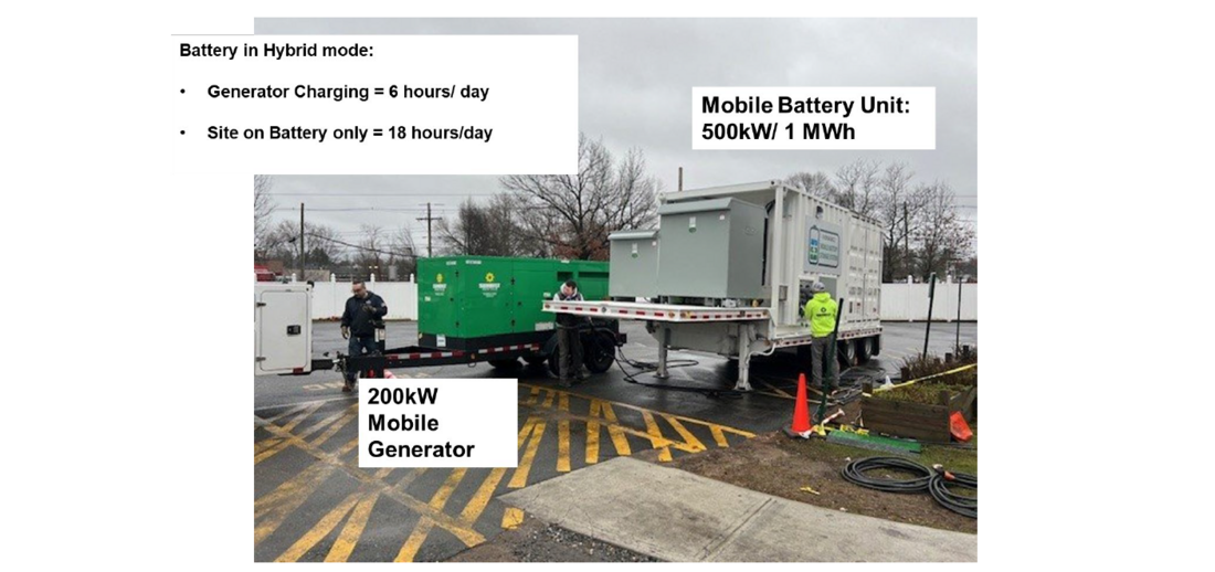
Figure 4 - Pairing of MBESS and a genset for sustained outage – logistics and ratings
A one-line diagram of the installation and pairing of MBESS with a genset unit to supply the business complex (load) is shown in Figure 5. The MBESS is the primary source supplying the load if there is enough energy in the batteries. Once the state of charge (SOC) of the battery units is low (e.g. approaching 10% remaining energy), MBESS automatically starts the genset (using auto start hardwired connection to genset).
The genset is connected to the infeed terminals of the MBESS unit – requiring a synchronization between two sources - the MBESS that is supplying the load and the genset after the start up. Once properly synchronized, MBESS closes the infeed generation circuit breaker (CBG) to initiate a re-charging process. The genset charges the batteries while the MBESS plus genset supplying the load – making the whole process seamless. The sizing and selection of the genset should be in a way that re-charging rate of MBESS would be close to the optimal loading expected on the genset (about 80-85% of the genset rated power) – to ensure best fuel efficiency during the recharge process.
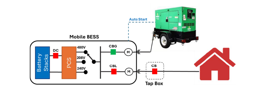
Figure 5 – One Line Diagram of the Pairing for Scheduled Outage
4.1.1. Pilot 1 Outcome
Pilot 1 helped to assess the real value of pairing a MBESS and a genset for an extended operation. Comparison of the originally estimated fuel consumption for a case of diesel-only operation, and the real fuel consumption of hybrid operation showed 20% diesel fuel reduction – translating directly into several tens of thousands of dollars in savings. The soft benefits are even more valuable – providing:
- Quiet operation in the daytime and weekends
- Eliminating fumes during business hours
- Flexible scheduling of the maintenance crew working hours – not requiring 24/7 hr supervision,
- Significantly reducing the operators and support crew engagement with the field – by expanding the remote monitoring and controls.
- Gathering extensive real-world data on the operation helping the understanding of the maintenance processes, scheduling and business case.
In addition, it was also shown that by utilizing these type of hybrid solutions, the field operation team can gain flexibility to more freely schedule the maintenance time in the daytime (regular working shift) rather than night-time which would have required special crew designation and overtime payments. This aspect was a key benefit and an option that was not possible when using diesel gensets, due to the genset noise if used in business hours.
4.2. Pilot 2 – Seasonal Excess Generation and Peak Load Management (Hosting Capacity Enhancement)
In most areas summer months are associated with heat waves, high solar PV production, and temporary high load (in certain hors) due to population increase (tourist attraction and destinations) or extensive use of air-conditioning systems. Example of excess generation is the high solar PV production in the middle of summer sunny days – part of the hosting capacity considerations that could prevent or delay deployment of more resources.
Excessive solar PV production or excessive load demand both have typically major adverse impact on the grid operation, causing congestion and power quality issues. The difference in timing of PV production (middle of day) and high demand (toward late afternoon and evening) could be the issue of turning the adverse impact into a true benefit.
Because it is a seasonal phenomenon, it becomes harder to justify a permanent (stationary) energy storage system. However, the use of MBESS can become the NWA solution for storing excess production and shifting the energy to properly correspond to the load – which is normally a period between 5 pm to 7 pm in northeastern cities.
To prove the viability and gain firsthand experience with this NWA use case, the utility deployed two MBESS in parallel connected to a medium voltage feeder (through a pad mount transformer) to pair the units with an existing 750 kW of PV carport- as shown in Figure 6. The PV system is part of the utility service centre, in which date time loads are much lower than evening loads – when utility crews are out on mission. The difference between the forecasted PV production and estimated facility load were utilized for charging profile of the battery. The daily discharge was scheduled for 5 pm to 7 pm at full power rating.
Two objectives were achieved and demonstrated – first, by storing the excess PV production, the reverse power flow on the feeder was prevented and at the same time, the need for curtailment reduced to almost zero percentage (i.e. production gain). As the second benefit, the stored energy was discharged to the grid in the later hours of the evening – greatly helping to reduce the peak load when energy rates ($/kWh) are super high.
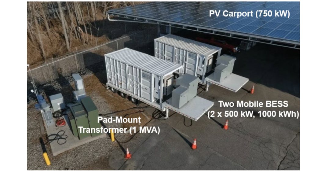
Figure 6 – Pairing of MBESS with Solar PV System (Hosting Capacity Enhancement)
4.2.1. Pilot 2 Outcome
Pilot 2 was an experimental demonstration as a proof of concept and proof of value for utilizing energy storage in an NWA approach for enhancing hosting capacity of a feeder. In addition, the pilot project also provided a means of quantifying value of DER for feeders with seasonal overloading and congestion conditions. The main observation from the pilot demonstration were:
- Avoiding PV curtailment and taking advantage of full PV production benefit – noting that curtailment would drop the revenue, while energy shifting will result in the total production revenue gain.
- Managing the feeder voltage during both high PV production (daytime) and peak loading of the feeder (evening time). The mobile BESS was able to provide an added value of feeder voltage management by absorbing reactive power in the daytime and injecting reactive power at night time.
- Although the evening discharge schedule was fixed between the hours of 5 pm to 7 pm, it was shown that secondary feedback signals, such as the reduction in the feeder voltage or direct signals from control centres could be potentially used to adjust the starting time of the peak shaving process.
Overall, this pilot project required more coordination among multiple departments within the utility stakeholders to properly plan for various aspects of operating mobile BESS in conjunction with a PV site that is under power purchase contract. Although the deployment site in this case was owned by one of the utility departments, in a more general case, the site utilization may also require coordination with a third-party customer for permission to deploy at a site.
5. Standardization
Several aspects of MBESS would benefit from standardization to help both utilities and manufacturers better manage the asset life cycle and to accelerate large scale adoption of the technology.
5.1. Emerging Technology
While stationary battery energy storage systems (BESS) have been widely deployed for over two decades, mobile battery energy storage systems are a newer, more flexible solution gaining traction. MBESS units are typically systems mounted on trailers or skid-mounted containers as a fully mobile units or integrated in a way that make them transportable / relocatable. They offer unique advantages such as:
- Rapid deployment during grid emergencies or peak demand.
- Temporary support for planned outages or construction.
- Grid services in remote or underserved areas.
- Revenue stacking through multi-site utilization.
However, the lack of standardization in MBESS design, interconnection, and operation poses challenges to scalability, safety, and interoperability.
5.2. Benefits of Standardization
The key benefits of standardization for electric and gas utilities specifically, and/or other service providers and private entities in general are:
- Interoperability: Standardized interfaces and communication protocols (for third party interface) allow seamless integration with various grid IT/OT systems, such as utility SCADA, or DMS – optionally utilized for operator monitoring, situational awareness and/or remote start / stop.
- Operational Efficiency: Streamlined deployment, commissioning, and control reduce labor and time costs.
- Grid Reliability: Consistent performance and safety standards enhance grid stability.
- Regulatory Compliance: Easier alignment with evolving energy regulations and codes, including safety compliance.
Some additional benefits of standardization specific to commercial entities and fleet owners are
- Asset Portability: Standardized designs enable use across multiple sites and utility territories.
- Lower Costs: Economies of scale in manufacturing and maintenance.
- Faster ROI: Reduced engineering and permitting time accelerate deployment.
- Third-Party Services: Easier to contract and integrate with energy-as-a-service providers.
5.3. Proposed Approach to Standardization
Over the last several years, some standardization initiatives have started through a specific IEEE industry connection activity focusing on the technology and business case for mobile energy storage [2]. Some other standardization entities have also started including the mobile energy storage in the revision of standards such as NFPA 855, and UL1973. Documenting the approach and outcome from multiple utility pilot projects are the more consistent and valuable information sources for standardization like the work described in this paper or other technical articles and contributions on this topic [4]. The following subsections provide a summary of proposed roadmap and some areas that can be prioritized in focusing on standardization activities.
5.3.1. Topology
- Modular Design: Define standard module sizes (e.g., 500 kWh, 1 MWh) and configurations (AC/DC coupling).
- Safety: This is integral part of the design and selection of technologies that support safety compliance and incorporate redundance to avoid single point of failure.
- Containerization: Use ISO-standard containers for transport and deployment.
- Thermal Management: Standardize cooling/heating systems for consistent performance.
5.3.2. Interconnection
- Plug-and-Play Interfaces: Develop standardized connectors for power and communications.
- Grid Codes Compliance: Align with IEEE 1547, UL 9540, and local interconnection standards.
- Rapid Permitting Templates: Create pre-approved interconnection templates for utilities.
5.3.3. Operation Platform
- Unified Control Systems: Standard APIs and protocols (e.g., DNP3, IEC 61850, and OPC UA).
- Cybersecurity Standards: Implement NERC CIP or equivalent frameworks.
- Remote Monitoring: Standard dashboards and telemetry for fleet management.
5.3.4. Maintenance
- Predictive Maintenance Protocols: Standardize data collection for supporting routine inspection and diagnostics.
- Serviceability Design: Modular components for easy replacement and repair.
- Training & Certification: Develop industry-wide training programs for technicians.
5.4. Implementation Roadmap
To offer a structured standardization roadmap for MBESS, some effort has started that intend to support and grow the standardization activities in the context of industry consortiums and working groups. The focus is to bring together utilities, original equipment manufacturers (OEMs), regulators, and commercial users to collaboratively define guidelines and manage change processes.
MBESS units should then be deployed across diverse pilot projects to validate performance and identify operational challenges. Insights from these deployments can inform the development of formal standards in collaboration with established bodies such as IEEE, UL, and IEC to formalize technical requirements. Simultaneously, policy advocacy efforts should engage regulatory agencies to promote adoption through incentives such as grants or mandates. A continuous feedback loop, driven by real-world field data, will be critical to refining standards and evolving best practices, ensuring the technology remains responsive to emerging needs and scalable across various use cases.
6. Conclusion
While stationary battery energy storage systems (BESS) have been widely utilized for over two decades, mobile battery energy storage systems (MBESS) represent a newer, more adaptable solution that is rapidly gaining momentum. Typically mounted on trailers or skid-based containers, MBESS units offer distinct advantages, including:
- Rapid deployment during grid emergencies or peak demand periods
- Temporary support during planned outages or construction activities
- Provision of grid services in remote or underserved regions
- Revenue optimization through flexible, multi-site utilization
This paper has presented real-world insights from multiple pilot projects that demonstrate the practical value of MBESS in delivering temporary non-wires alternatives (NWA) and outage relief services within utility environments. These pilots highlight both the challenges encountered and the solutions developed across key utility functions such as use case selection, planning, deployment, and operational integration.
To support broader adoption, a standardization roadmap is proposed to address critical challenges in lifecycle management and interoperability. The lessons learned from these pilot deployments, combined with the emphasis on standardization, aim to accelerate the deployment of mobile energy storage solutions and support their growing role in modern grid resilience and flexibility.
References
- "Mobile Energy Storage Systems: A Grid-Edge Technology to Enhance Reliability and Resilience," in IEEE Power and Energy Magazine, vol. 21, no. 2, pp. 97-105, March-April 2023
- "Mobile and Transportable Energy Storage Systems: Business Case and Benchmark Analysis," in Mobile and Transportable Energy Storage Systems: Business Case and Benchmark Analysis, vol., no., pp.1-26, 15 Nov. 2024.
- "IEEE Guide for Design, Operation, and Maintenance of Battery Energy Storage Systems, both Stationary and Mobile, and Applications Integrated with Electric Power Systems," in IEEE Std 2030.2.1-2019, vol., no., pp.1-45, 13 Dec. 2019.
- "Seasonal Overload Mitigation in Rural Distribution Feeders using Mobile Energy Storage System," in CIGRE Grid of Future Symposium, Oct, 2024.