Challenges faced by TSO to specify, test and integrate EMT models of IBRs to support grid stability
Authors
Sébastien DENNETIERE, Yannick VERNAY, Mickael THIBERT, Fabien MORRETTON, Elias MBEROU - RTE, France

Summary
The increasing penetration of Inverter-Based Resources (IBRs), such as solar photovoltaics and wind turbines, into the power grid has introduced new complexities in maintaining grid stability. Transmission System Operators (TSOs) are tasked with the critical responsibility of ensuring the stability and reliability of the electrical grid, which now involves the integration of diverse and intermittent energy sources. A crucial component of this process is the development and implementation of accurate Electromagnetic Transient (EMT) models of IBRs. These models are essential for simulating the dynamic behaviors of IBRs and their interactions with the grid, which are markedly different from those of traditional synchronous generators.
This paper provides an in-depth analysis of the challenges faced by TSOs in specifying, testing, and integrating EMT models of IBRs. The experience of the French TSO RTE (Réseau de Transport d'Electricité) is used to illustrate the paper. Firstly, the specification of EMT models requires a comprehensive understanding of the various IBR technologies and their operational characteristics. The diversity in technology, ranging from different types of inverters to varying control strategies, complicates the standardization of model specifications. Additionally, obtaining high-fidelity data necessary for accurate modeling is often hindered by proprietary constraints and the variability of IBR performance under different operating conditions.
Testing these models presents another significant challenge. EMT models must undergo rigorous validation to ensure their accuracy and reliability. This involves benchmarking against various references and field validation to compare model predictions with actual system behavior. The complexity of the power grid, combined with the dynamic nature of IBRs, necessitates advanced testing protocols that can capture transient phenomena and non-linear characteristics. The paper discusses the techniques applied in France in model validation and highlights the need for improved testing facilities and methodologies.
The integration of validated EMT models into grid stability frameworks is the final step, which is fraught with its own set of difficulties. TSOs must ensure that these models are compatible with existing grid simulation tools. The interoperability of different models and the scalability of integration processes are critical factors that influence the overall effectiveness of grid management. The paper examines current practices in model integration, identifies gaps, and proposes strategies to enhance the integration process. The paper also addresses improvements in existing EMT simulation tools to facilitate integration of these complex models.
Furthermore, the paper explores the regulatory and collaborative aspects that impact the specification, testing, and integration of EMT models. Regulatory frameworks need to evolve to support the widespread adoption of IBRs, providing guidelines for model accuracy and data transparency. Collaboration between TSOs, IBR manufacturers, and research institutions is essential to address the technical challenges and foster innovation in modeling and simulation techniques.
In conclusion, the paper underscores the importance of robust EMT modeling of IBRs for the stability of future power grids. By addressing the challenges in specification, testing, and integration, TSOs can enhance their capability to manage the growing share of renewable energy sources, ensuring a reliable and resilient power system. The insights and recommendations presented in this paper aim to contribute to the ongoing efforts to modernize grid operations and support the transition to a sustainable energy future.
Keywords
EMT simulation, IBR integration, Grid code requirements1. Introduction
The integration of Inverter-Based Resources (IBRs), such as solar photovoltaics and wind turbines, into modern power grids is rapidly transforming the landscape of grid stability. Transmission System Operators (TSOs) face the critical challenge of maintaining the stability and reliability of the grid while accommodating the unique characteristics of diverse and intermittent energy sources. Accurate Electromagnetic Transient (EMT) models of IBRs play a pivotal role in this endeavour, enabling the detailed simulation of their dynamic behaviors and interactions with the grid, which differ significantly from those of conventional synchronous generators.
In recent years, there has been growing interest in these tools, largely driven by the limitations identified in dynamic simulation tools based on the 'phasor' approach. These tools, traditionally employed by grid operators, represent converters and their control systems in a relatively simplified manner. The limitations of such tools in accurately modeling converters and their control systems have been well-documented, particularly in the context of major grid events (e.g., Texas, Australia, and the United Kingdom). These events demonstrated that phasor-type models were not sufficiently representative of on-site installations, unlike EMT models [1]-[2]. As a result, EMT tools are now recognized as essential for studying the dynamic behavior of electrical systems. Their initial scope, which was limited to equipment studies, has been greatly expanded. For many TSOs, the use of EMT tools has become a critical factor in ensuring the stability of the electrical grid.
For a given IBR, multiple types of EMT models may be available, each designed for a specific purpose and with a defined range of applicability. The focus of the EMT models considered in this paper is on dynamic performance studies conducted at the system level. As highlighted in [3], utilities typically perform various integration studies for IBRs to evaluate, anticipate, or analyze potential issues. Depending on the phase of the project and the specific requirements of the utility, different types of EMT models may be employed. These models can generally be classified into three main categories [4]: generic models, manufacturer-specific models, and control and protection (C&P) cubicles used in real-time simulations.
A generic model is defined as one developed based on general principles and concepts. Such models are designed for broad applicability across a wide range of projects, requiring only minor reconfiguration or modification. However, to be effective, a generic model must be sufficiently comprehensive to accurately represent the area or performance under study. For instance, the accurate reproduction of fast front waveform responses in the control system would require the inclusion of realistic measurement elements alongside the relevant control loops. Similarly, conducting multiple fault ride-through analyses would necessitate the model's incorporation of both fast-acting and slow-acting protection mechanisms. While generic models can effectively simulate certain dynamic behaviours and small perturbations, their ability to address a wider range of phenomena may be limited, particularly when nonlinear transients or significant disturbances are involved.
The manufacturer’s black-box model is specifically developed for a particular project. To safeguard intellectual property (IP), these models are typically provided to utilities in a black-boxed format, meaning their internal structure is not fully accessible. Such models contain precise data about the power circuit, the configuration of the actual project, and the C&P systems required for offline EMT simulations. Some simplifications are often applied to the C&P systems; for example, certain functions, such as start-up and shut-down sequences, are simplified or accelerated to reduce simulation time.
In phasor-domain (RMS – Root Mean Square) tools, the manufacturer’s black-box model incorporates only the C&P functions relevant for network stability studies, as not all functions, particularly fast control loops, can be implemented in these tools. Conversely, in EMT tools, the black-box model includes a detailed representation (or a close approximation) of all C&P functions necessary for offline EMT simulations. However, slower control functions, such as run-back functionalities, AC emulation, and power oscillation damping (POD), are generally simplified. The EMT model also incorporates relevant protection functions to ensure accurate representation of the system dynamics.
Unlike the two previously discussed types of IBR models (i.e., generic and black-boxed models), the 3rd approach utilizes a real-time simulator. The Hardware-in-the-Loop (HIL) setup is a methodology employed to test and develop complex physical C&P systems. A HIL setup consists of the following components:
- A real-time simulator to emulate the power system network.
- Physical C&P system cubicles.
- Input/output (I/O) interfaces connecting the plant simulation with the C&P system under test.
Since the physical C&P cubicles are directly represented in this setup, the HIL approach serves as the reference model for validating C&P functions. These cubicles may be the actual units deployed on-site or replicas, as described in subsequent sections. The HIL solution has been employed for several decades in the context of HVDC systems. For IBR applications such as wind farms, photovoltaic (PV) plants, and Battery Energy Storage Systems (BESS), an alternative approach based on the real control code executed on simulation hardware, referred to as Software-in-the-Loop (SIL), can also be considered as described in [5].
This paper focuses on the use of manufacturer-provided black-box models by System Operators (SOs) for analyzing the dynamic behavior of electrical systems in offline and real-time simulations. The experience of the French TSO RTE is used to illustrate this paper. Even if the main focus is the EMT model of IBRs, the approach presented in the paper is similar for all converter-based equipment connected to the French transmission grid including BESS and Inverter-Based Load (IBL). The first section outlines the specifications for EMT models in France, along with their evolution and underlying justifications. The second section describes the step-by-step process for validating these models. Finally, the integration of EMT models into grid stability frameworks is examined.
2. EMT model specifications
The EMT models discussed in this paper are specifically designed for dynamic performance studies conducted at the system level by SOs. These models are initially developed by the Original Equipment Manufacturers (OEMs) of IBRs with the primary objective of tuning the C&P systems to meet the dynamic performance requirements stipulated in the applicable grid codes. Moreover, the provision of EMT models has become an integral component of grid code compliance, ensuring that the delivered models accurately reflect the system's dynamic behaviour and support the detailed analyses required for secure and reliable grid operation. The EMT model requirements applicable in France for offline and real-time simulation are described in the following sections.
2.1. Grid code requirement in France for EMT offline models
The grid code requirements for EMT models in the context of IBR connection are described in [6] and are summarized in the present section. They apply to Power Park Modules (PPM) generating active power equal or above 18MW or connected to a grid voltage level equal or above 110kV as described in Figure 1.

Figure 1 – EMT model requirements applied for C & D type PPM in France
The requirements concern data and models for conducting dynamic studies aimed at simulating the behaviour of generation unit, particularly in relation to EMT phenomena. These models must accurately represent the transient behaviour (including rapid dynamics for frequencies ranging from 0.2 Hz to 10 kHz) in direct, inverse, and zero-sequence component of the generation unit. The models must, at a minimum, enable the following analyses:
- Studies of subsynchronous phenomena (torsional interactions with the transmission network at subsynchronous frequencies),
- Analyses of the generation unit's behavior during faults and rapid electromagnetic transients,
- Harmonic stability studies,
- Control system interaction analyses.
To facilitate pre-connection studies for the generation unit, data are provided in two stages: preliminary data 18 months prior to the first power injection and final data 8 months prior to the first power injection. Three types of data must be provided by the producer to RTE:
- Detailed electrical characteristics of the equipment used.
- A numerical model of the control, protection, and automation systems.
- An EMT model, or a model compatible with the EMT-type software used for the design and tuning studies of the installation.
The complete set of characteristics for the high-voltage components (transformers, cables, compensation and/or filtering systems, rotating machines, power-electronics-based converters, surge arresters, etc.) must be provided in a document to enable EMT-type modeling. These characteristics should be accompanied by a single-line diagram of the installation. The data provided must not involve any aggregation. For example, in the case of a wind generation unit, the individual characteristics of each turbine, the characteristics of the cables and transformers connecting each turbine, and the characteristics of the converters used at each turbine must be supplied. It shall be possible to use multiple instances of the model on the same circuit without using parallel computing.
The representation of the C&P systems must be included in the model and derived from the actual code implemented on-site. The C&P model must be delivered in DLL format and adhere to the IEEE/CIGRE interface specifications as defined by CIGRE Working Group B4.82 [7]. This requirement is critical to ensure the delivery of tool-independent C&P models. These models must be compatible with any version of an EMT simulation tool and remain functional even if the TSO decides to adopt a different EMT simulation tool. The primary motivation for this requirement is to guarantee the usability of the models throughout the entire operational lifetime of the on-site system. Additionally, as electrical equipment model data must remain accessible, it is more straightforward for these models to adapt to the evolution of simulation tools.
To ensure compatibility for interaction studies involving models from multiple vendors, the model results must remain valid for simulation time steps of 10 μs and multiples thereof, up to a maximum of 50 μs.
The French grid code does not mandate the use of a specific EMT simulation tool. The choice of format of the delivered EMT model depends on the software employed by the supplier or developer for tuning the C&P. If the model is initially provided in an EMT tool that is not used by RTE, it will be converted to the format used by RTE. Since the C&P model is provided as a tool-independent DLL, its integration into the EMT simulation tool used by RTE is straightforward. Once converted, this model will be the sole model utilized by RTE for conducting integration studies. An updated model must be delivered to RTE as soon as a modification of the installation on site (including change of equipment and/or change of C&P setting) is implemented.
2.2. Grid code requirements for EMT real-time simulation
EMT real-time simulation is employed when physical controllers are integrated into the simulation, typically in a HIL setup. This approach enables interaction studies between IBRs and HVDC or FACTS equipment. For such studies, it is essential to include an appropriate representation of the IBR in the simulation setup. This representation can be a tuned generic model or a vendor-specific black-box model capable of running in real time. The present section focuses on this type of modeling approach.
A typical application scenario involves an HVDC link connecting an offshore wind farm (OWF) to the onshore transmission grid, as illustrated in Figure 2. In this configuration, the HVDC link is interfaced with a physical C&P system replica, while the OWF is represented within the real-time simulation environment. All relevant OWF C&P functionalities run on a generic hardware platform, creating a hybrid HIL/SIL setup. As required for EMT offline simulations, the C&P model executed in the SIL setup must be generated directly from the real control code.
The requirements for delivering such EMT real-time simulation models are outlined in [8], and their inclusion in the French grid code requirements is currently under consideration.
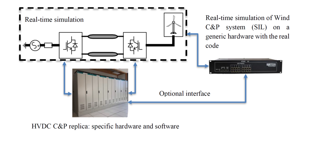
Figure 2 – HIL/SIL mixed solution to analyse dynamic behavior of OWF connected with HVDC
3. EMT models testing
The present section concerns the testing methodology of offline EMT models applied by the French TSO RTE. Testing of the EMT models includes 2 steps. The first step is verification to identify defects, inconsistencies, and deviations from the intended design of the model. The second step is validation to ensure that the model satisfy the intended purpose. This second step involves comparison of the model against real-world measurement.
The EMT model requirements apply to different types of IBR such as wind farms, PV power plants and BESS. A schematic diagram illustrating the connection of an IBR is presented in Figure 3. While the diagram is designed to be as generic as possible, certain adaptations may be made to accommodate specific project requirements.
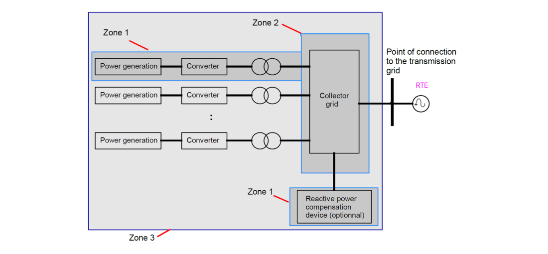
Figure 3 – Generic representation of IBR connection used for the EMT testing
3.1. EMT models verification steps
The objective of this step is to verify that the IBR model developed in the EMT simulation tool used by RTE provides consistent results with the models used by the IBR OEM and the IBR owner/operator for their design and performance studies. The dynamic performance of the IBR itself is not verified in this process. The verification process follows a three-step approach based on the representation of the IBR system shown in Figure 3:
-
Zone 1 (Single Unit): A benchmark is conducted between the IBR EMT model used by RTE and the EMT model originally used for dynamic performance studies of the IBR. This first step is not required when the IBR owner/operator provides a single unit model directly implemented in EMT tool used by RTE.
-
Zone 2 (Internal Grid): A benchmark is performed at various grid nodes to compare the harmonic impedance calculated in the EMT environment used by RTE with the harmonic impedance estimated by the IBR owner/operator using the harmonic simulation tool employed during the planning phase. If this zone includes a power-electronic-based reactive power support device, the verification process for this equipment will follow the same approach as Zone 1. This second step is not required when the IBR owner/operator provides an entire plant model in EMT simulation tool used by RTE.
-
Zone 3 (Entire Plant): A benchmark is carried out to compare the results of plant-level dynamic performance studies performed by the IBR owner/operator, often using an RMS simulation tool, with the corresponding results obtained from EMT model used by RTE.
For each verification step, the relevant conditions, and events to be simulated are specified. Additionally, the required signals and acceptance criteria are detailed in the grid code requirements. This verification step corresponds to "Fiche I11" in [6].
3.2. EMT model validation step
The validation step involves comparing the EMT model against real-world measurements to ensure it accurately represents the actual on-site installation. No specific site tests are required solely for EMT model validation. Instead, pre-defined on-site tests, such as set-point step tests, energization tests, and frequency performance tests—outlined in the grid code [6]—are used. The results recorded on-site are compared with those obtained from the EMT plant model. The selection of on-site tests and the recorded signals used for validation is a collaborative effort between RTE and the IBR owner/operator. A minimum set of requirements (location of measured signals and sampling rates) are described in the grid code. This validation process corresponds to "Fiche F15" as defined in [6].
3.3. Illustrations and learnings from real projects
The verification steps for EMT models were incorporated into the grid code requirements in 2020. In 2023 and 2024, RTE received approximately 10 EMT models annually. Given the recent introduction of these requirements, an adaptation phase was necessary, during which discrepancies were identified between the expected model specifications and those submitted by customers. Through collaborative efforts with all stakeholders, the grid code requirements have been clarified and updated, leading to improved understanding and alignment.
When models are not provided in the EMT tool used by RTE, RTE imports these models using a dedicated import tool. The C&P black-box components, provided as compiled code, are imported automatically without modifications to ensure complete consistency between the simulation tools. The IEEE/CIGRE DLL interface requirement [7] has simplified this process, making it easier to maintain EMT models even as new versions of EMT simulation tools are released.
The first verification step focuses on Zone 1, as shown in Figure 3. RTE assembles the EMT model using data provided by the customer, and verification tests are conducted by benchmarking the results provided by both EMT models. In most cases, a very close match was achieved between the two models. However, perfect alignment is not expected due to differences in modeling techniques between the simulation tools, such as the representation of nonlinear devices like transformer saturation and surge arresters. Figure 4 and Figure 5 illustrate an example of benchmarking a wind turbine (WT) model (single unit) when a 1-phase to ground fault is initiated at WT 66kV terminals. In these figures, V1_grid and I1_grid represent the positive-sequence voltage and current at the WT 66kV terminals, while Vgrid and Igrid denote the instantaneous voltage and current at the same location.
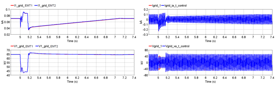
Figure 4 – EMT model verification step 1 – benchmark delivered EMT (EMT1) model vs EMT model developed by RTE (EMT2)
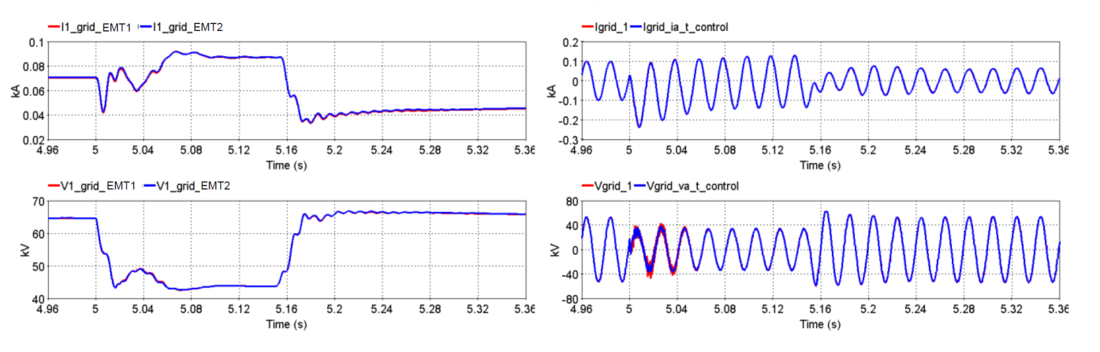
Figure 5 - EMT model verification step 1 – benchmark delivered EMT model (EMT1) vs EMT model developed by RTE (EMT2) - Zoom
The second verification step focuses on the harmonic impedance data of the collector grid (Zone 2). The comparison process can be somewhat challenging when RTE does not receive the raw harmonic impedance data assessed by the customer. However, in most cases, this comparison does not result in significant issues.
The final verification step involves comparing the results obtained from the EMT model (executed by RTE) with those obtained by the customer for dynamic performance studies (mainly executed with RMS models). The main challenges to perform this step are the fundamental differences between EMT and RMS modeling techniques, and as the RMS studies are conducted by the customer, the inherent difficulty in fully understanding all the modeling assumptions and selected parameters. This process requires discussions with the customers. An example of a comparison conducted during this stage of the verification process is presented in Figure 6. This example pertains to an onshore wind farm (WF), where a three-phase solid fault is initiated at t=0s within the WF. Positive sequence voltage and current simulated by the WF developer in an RMS tool are superimposed with the positive sequence voltage and current simulated by RTE with the EMT model (see Figure 6). The entire WF has been modeled in detail in both simulation tools without any aggregation. Measurements are done at the WF point of interface with the transmission grid.
Differences between RMS and EMT results can be observed. These discrepancies primarily arise from the calculation of positive sequence values in EMT simulations, which are derived from instantaneous values and require one period to stabilize. Additionally, a deviation of approximately 2% in the remaining voltage during a fault can be noted. However, these differences remain within the expected tolerance specified by the Grid Code requirements. The main objective of this step is to verify that the dynamic behavior and the current contribution during fault is similar in the 2 types of simulation tools.
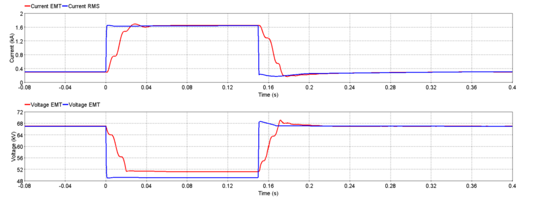
Figure 6 - EMT model verification step 3– benchmark RMS model vs EMT model
The EMT model validation step is a complex process that requires the active involvement of multiple stakeholders to ensure on-site tests are conducted as intended. Several challenges have been identified, including:
- Recording Location: Ensuring that measurements are taken at the most relevant points in the system for meaningful analysis.
- Measuring Devices: Implementing appropriate measurement devices with sufficient frequency bandwidth and recording systems with adequate sampling rates.
- Test Conditions: Accurately recording the test conditions to enable precise replication in the EMT simulation tool.
- Data Format: Providing recordings in a format compatible with EMT simulation tools for effective comparison.
- Collaboration: Engaging in constructive dialogue with the IBR owner/operator to identify and understand differences between on-site measurements and simulation results.
A successful validation example is described in [9], involving a BESS connected to the French transmission grid. Figure 7 illustrates the comparison for a frequency perturbation injected during on-site testing.
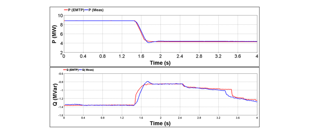
Figure 7 – EMT model validation - Active and reactive power for a frequency step of 1.45 Hz
However, RTE has encountered significant difficulties in completing the validation step for a substantial number of IBR projects. Many developers do not recognize EMT model validation as a critical requirement for connecting their systems to the transmission grid. This oversight arises from various factors, including a lack of awareness of its importance and the challenges involved in executing the process effectively. This situation must change due to the critical impact of IBRs on transmission grid stability and performance. Without thorough validation, there is a risk of incomplete or inaccurate EMT models, which can lead to misrepresentation of the dynamic behavior of IBRs. This, in turn, poses serious risks to grid planning, operation, and reliability. Developers must prioritize the EMT model validation step to ensure their projects meet the necessary standards for grid integration and to contribute to the overall stability and robustness of the transmission system.
4. EMT model integration challenges
Once EMT models of IBRs have been verified and tested as outlined in Section 3, they can be applied to a variety of studies. One application is post-event analysis, where the model is used to investigate unexpected behavior observed on-site. However, a primary application is the study of interactions between the IBR and the surrounding grid, either during the planning stage or during operation. This type of analysis is becoming increasingly critical for assessing grid stability. To support this growing need, several key factors have been identified to ensure the effective integration of IBR EMT models into a simulation framework for network stability assessment at RTE. These factors include:
- Model Performance: Ensuring the models are computationally efficient and capable of accurately representing dynamic behavior.
- Grid Data Portability: Facilitating seamless integration of grid data into the simulation environment.
- Model Accessibility: Guaranteeing that models are readily accessible to stakeholders while maintaining confidentiality and compliance with data-sharing protocols.
4.1. Model performance
The first factor addresses the performance of EMT models from the perspective of the simulation tool. Optimizing the computation time of IBR models is crucial to enable simulations involving multiple IBRs efficiently. Additionally, ensuring the interoperability of these models is vital to confirm that they function correctly when integrated with other IBR models within the same simulation framework.
These performance aspects are governed by the EMT model requirements outlined in Section 2.1, which include considerations such as time-step optimization, tool-independent DLL implementation, and other key criteria.
4.2. Grid data
The second factor emphasizes the importance of ensuring consistency between the transmission grid data used for EMT studies and the data utilized for other types of studies, such as load-flow analysis, short-circuit calculations, dynamic studies in the phasor domain, and harmonic analysis. This consistency is particularly critical for large-scale studies, where discrepancies can compromise the reliability of the results.
Employing a standardized format for data portability greatly facilitates the exchange of power system network information between different simulation tools. The Common Information Model (CIM) has proven to be the leading standard for power system data exchange and is now widely recognized as an international reference for simulation tools with portable data formats.
At RTE, a CIM-based interface has been developed and maintained for over 10 years to automate the import of grid data from SCADA platforms into an EMT simulation tool. This interface, detailed in [10], plays a pivotal role in RTE’s simulation framework by ensuring grid data consistency and simplifying the management of grid models, even for engineers who may not be familiar with large-scale EMT models. An example of a large EMT grid model imported using this interface and employed in an integration study is presented in [11].
4.3. Model accessibility
Dynamic performance requirements are typically assessed using a simplified Thevenin equivalent of the transmission system or other reduced representations. While these equivalents enable a limited set of tests, the responsibility often falls to the TSO to perform more comprehensive simulations using a detailed and precise model of the transmission grid. This approach is time-intensive and frequently involves multiple iterations between stakeholders, particularly in complex grids with numerous interacting IBRs. Sharing the complete TSO grid model with IBR owners or operators is often not feasible due to security concerns or the inclusion of proprietary or confidential models governed by non-disclosure agreements. To address these challenges, several initiatives in recent years have focused on developing a "connection tool" for EMT simulations.
This concept involves creating an EMT grid model that integrates numerous black-box representations of IBRs, which the TSO cannot disclose to external parties. For a new IBR connection project, the TSO can provide the IBR developer with access to this grid model through a secure EMT simulation platform. In this setup, the grid model is protected, and the developer is only provided with an electrical interface at the point of connection. The IBR developer can then test various versions or configurations of their equipment connected to the grid model without gaining visibility into the grid’s internal details.
While several technical solutions for implementing this approach have been developed [12]-[13], further optimization is needed to enhance its efficiency and usability. These advancements aim to streamline the connection process and support the effective integration of IBRs into the transmission grid. RTE is involved in a project to develop such a tool [13].
5. Conclusion
The integration of large volumes of IBRs into transmission grids poses significant challenges to the stability of the electrical system. This issue is increasingly becoming a major concern for the industry and impacts the ability of TSOs to accommodate high levels of renewable energy sources. One solution to facilitate the integration of IBRs and mitigate the risk of stability issues is to conduct studies using accurate and efficient EMT models of these resources. The paper underscores the importance of robust EMT modeling of IBRs for the stability of future power grids. The challenges experienced by RTE in specification, testing, and integration have been described.
EMT model requirements for IBRs are relatively new in France and have been progressively refined through a collaborative approach involving all stakeholders. Cooperation between TSOs and IBR manufacturers is crucial to addressing technical challenges, particularly the delivery of validated models. RTE has faced significant challenges in obtaining validated models for a substantial number of IBR projects. Many developers fail to recognize EMT model validation as a critical requirement for connecting their systems to the transmission grid. This mindset must change, given the critical impact of IBRs on the stability and performance of the transmission grid. Developers must prioritize EMT model validation to ensure their projects comply with the necessary standards for grid integration and to support the overall stability and resilience of the transmission system.
The current validation and testing process at RTE requires significant EMT expertise. In 2023 and 2024, this process demanded the equivalent of one to two full-time engineers. With the expected increase in the number of IBRs connecting to the grid in the coming years, several measures have been implemented to optimize resource allocation. Dedicated automation tools have been developed to streamline the process, and the tool-independent interface for C&P models, as described in [7], has been incorporated into the grid code requirements to simplify validation and accelerate grid connection agreements.
References
- " Odessa Disturbance", Texas Events: May 9, 2021 and June 26, 2021 Joint NERC and Texas RE Staff Report, September 2021, available online
- "Dynamic characteristics of inverter-based resources in bulk power systems" – Part 2: Sub- and super-synchronous control interactions, IEC Technical Report TR 63401-2, June 2022
- "Composite testing of HVDC-connected offshore wind farms", RTE international technical report, available online
- "Interaction between nearby VSC-HVDC converters, FACTs devices, HV power electronic devices and conventional AC equipment", CIGRE Technical Brochure 934, July 2024.
- Gomes Guerreiro, G. M., Negi, L., Medina, D., Kkuni, K. V., Sharma, R., Szczesny, I., Ghimire, S., Vilerá, K. V., Dreyer, T., & Yang, G. “Real-Time Software-in-the-Loop EMT Models of Wind Turbine and Power Plant Controller: Applicability and Experiences”. Paper presented at 23rd Wind & Solar Integration Workshop, Helsinki, Finland.
- French Grid code for PPM - "Cahier des charges des capacités constructives – Conditions générales – Parc non synchrones de générateurs" Section 3.11.2 available online
- "Guidelines for use of real-code in EMT models for HVDC, FACTS and inverter based generators in power systems analysis ", CIGRE TB 958, published in February 2025, CIGRE WG B4-82
- "Requirements for AC/DC converter stations, DC switching stations, Power Park Modules and DC Grid controller offline models, SIL models and C&P cubicles", Deliverable D1.1, InterOPERA project, June 2024, available online
- O. Saad, H. Honvo, A. Ajaja, S. Dennetière and Y. Vernay, "Battery energy storage system integration to the RTE network: from EMT studies to site validation," 22nd Wind and Solar Integration Workshop (WIW 2023), Copenhagen, Denmark, 2023, pp. 198-204, doi: 10.1049/icp.2023.2738.
- C. Martin, Y. Fillion, "Automation of model exchange between planning and EMT tools", Proceedings of the International Conference on Power Systems Transients (IPST) 2017, Seoul, Republic of Korea.
- B. Bruned, M. Ouafi, A. Petit, V. Costan, Y. Vernay, " Parallel simulation of a wide-area EMT model with high penetration of power electronic converters using co-simulation: a real case study", CIGRE Paris session, Ref. C4-10291-2024, C4 PS1, August 2024.
- AEMO Connection tool, information available online
- EMTP connection tool, available online