Inspections of composite insulators in service as an input in preventive maintenance
Authors
P. SIDENVALL, I. GUTMAN – I2G, Sweden
A. DECKWERTH - 50Hertz, Germany
L. DIAZ - RTE, France
K. HALSAN - Statnett, Norway
M. JALONEN - Fingrid, Finland
F. LEHRETZ - TenneT, Germany
M. LEONHARDSBERGER - APG, Austria
J. LÓPEZ OSUNA - Red Eléctrica, Spain
L. RASMUSSEN – Energinet, Denmark
T. SCHIML - Bayernwerk, Germany
K. VARLI - Amprion, Germany
D. WINDMAR - SVK, Sweden

Summary
Service inspections are a critical part of maintenance strategies for all types of overhead line components. Proper collection and evaluation of inspection data are essential for planning effective maintenance measures. Composite insulators have become a standard choice for modern overhead lines. Several quality issues with composite insulators have been identified, prompting the development of appropriate countermeasures. Some of these have already been incorporated into the latest revisions of composite insulator standards.
However, many installed composite insulators do not meet these updated standards. Some may even be of substandard quality, underscoring the need to verify the performance of existing installations. There is also a growing emphasis on improving inspection methods and diagnostic technologies for composite insulators. In this project, approximately 600 composite insulators were inspected, yielding valuable practical insights. The inspections identified several insulators that required replacement and revealed design errors in insulator strings, contributing to more informed future maintenance and design practices.
Keywords
Composite insulator, diagnostic methods, service inspections1. Introduction
At present composite insulators are an integral part of the transmission lines for many utilities. Dominant reasons for their application in comparison to ceramic insulators were revealed as cost-effectiveness, superior pollution performance and easier handling [1]. The combination of high mechanical strength and low weight also enables more aesthetically pleasing tower designs for new power lines, which appears to be a current trend. The global service experience of composite insulators has generally been positive and is considered comparable to that of glass insulators [1]. However, a review of recent service data has revealed several prevailing issues, primarily related to quality control during the manufacturing process. They were defined and thoroughly investigated: poor quality of fibreglass rods [2]-[4], low adhesion rod/housing [3]-[9] and excessive electric fields due to improper dimensioning and installation of grading rings [10]-[12]. These types of issues have in some cases led to deterioration and failures (typically referred as “flashunders”) causing line outages and in the worst-case line drops.
Composite insulators have undergone several generations of development and are now regarded as a mature and reliable product. This is particularly true when technical (purchase) specifications are kept up to date, and utilities actively participate in quality assurance and control during installation [13]. To further enhance the quality and reliability of composite insulators, a group of European utilities, in collaboration with the Independent Insulation Group, established an R&D consortium. This consortium has made significant efforts to improve composite insulators performance:
- First, a new test method was developed to reveal poor adhesion [3], [5], [9]. During its development, low-quality rods were also identified. As a result, recommendations were made to implement acceptance criteria that are ten times stricter than the then in force IEC standards for both the rod/housing interface and the rods themselves [3].
- In the next step, efforts were focused on verifying the electric field criteria for already-installed insulators [12]. The criteria for maximum electric field along insulators, as previously proposed by EPRI and STRI [10], [11] were slightly modified. These modifications were accepted by both industry and market stakeholders. Subsequently, even a new laboratory test was developed to validate the revised calculations [12].
- The newly introduced test methods were implemented at the design test level, with electric field criteria to be verified at the type test level. Many utilities have already adopted these methods into their technical requirements. The International Electrotechnical Commission (IEC) has fully integrated these updated tests into the latest revision of IEC 61109 [14], and IEC 62217 [15]. The new IEC standards are supported by comprehensive data presented in CIGRE Technical Brochure 919 [16], further validating these updates. These revised requirements are expected to significantly improve the quality and reliability of modern insulators. As a result, regular service inspections of this generation of insulators will no longer be necessary.
Many utilities still operate with an older fleet of composite insulators that have not been tested using the latest industry knowledge and standards. In such cases, service inspections become a vital tool for assessing the condition of these insulators and determining whether corrective maintenance is necessary. This paper focuses on practical experiences with the service inspection of composite insulators across various environments, sharing lessons learned from these inspections to improve maintenance strategies and enhance reliability.
1.1. Maintenance strategies
In managing the integrity of composite insulators, there are two primary maintenance strategies: preventive maintenance and reactive maintenance. Each approach has its distinct focus and implications for system reliability, cost, and operational efficiency.
Reactive maintenance is a failure-based approach that focuses on replacing or repairing insulators only after they have failed. This is typically a result of events like flashunder, which is the dominant type of failure for composite insulators [1]. Flashunder can lead to electrical short-circuiting or mechanical issues such as conductor drops, both of which can result in extended outages and system disruptions.
Preventive maintenance focuses on identifying and addressing issues before they lead to failures, based on the idea of anticipating problems and acting before the insulator reaches the end of its operational life. The core of this strategy involves establishing a health index or set of criteria to assess the condition of insulators and determine the optimal time for replacement or repair. Service inspections supported by after-service tests of removed from lines insulators is a common strategy for inspection-based preventive maintenance. After-service tests data not only enhances the understanding of insulator behaviour but also refines predictive models, making future maintenance efforts more precise.
Information about possible test matrixes for after service tests is presented in [17]. Currently, insulators chosen for testing after being in service are selected based on expert judgment and data from past service experiences. Ideally, after-service tests would be used to confirm the findings of service inspections, giving a more objective and thorough understanding of the insulator's condition.
Accordingly, service inspections serve as a critical source of input for corrective maintenance activities. A detailed discussion of the insights gained from these inspections follows.
2. Inspections
Utilities perform several types of inspections on composite insulators throughout their service life, at various stages and using different methods. Initially, some utilities are involved during the manufacturing process by participating in Factory Acceptance Tests (FAT). Subsequent inspections may also take place before the overhead line is commissioned and energized. However, these early-stage inspections are limited in scope and may fail to detect hidden defects and quality issues not covered by the existing standards.
To ensure ongoing reliability, utilities conduct periodic inspections while the insulators are in service. The frequency and extent of these inspections can vary significantly depending on the specific types of flaws being targeted. The most common method is visual inspection, which can be carried out from the ground, by climbing towers, or using aerial platforms such as drones or helicopters. These inspections are relatively accessible but are primarily capable of identifying surface defects, which may in some cases indicate underlying internal damage. To gain a more comprehensive understanding of the insulator's condition, especially to detect internal or developing issues, additional diagnostic technologies are often required.
The inspections described in this paper were conducted in three countries with diverse geographical and environmental conditions, aiming to provide relevant data across a wide range of installations. The inspected insulators had been in service for periods ranging from 1 to 29 years, with about 600 insulators examined. All inspections were performed from the ground using various diagnostic techniques.
2.1. Instruments/technologies: compressed review
A variety of inspection technologies have been employed to detect and understand different types of defects arising from design flaws, manufacturing quality issues, improper installation, and age-related deterioration. Many of the technologies in use today were already documented in CIGRE Technical Brochure 545 [18], published in 2013. However, since then, significant advancements have been made; existing technologies have improved, and new inspection methods have emerged, offering enhanced capabilities in identifying and analysing asset degradation.
2.1.1. Visual inspection
Visual Inspection is the most common method for assessing insulators and their protective devices. It is primarily effective for detecting visible surface deterioration and basic installation errors, such as missing or incorrectly placed grading rings. Utilities often rely solely on this technique, performing inspections at several years intervals using tools like binoculars, photo cameras, or video cameras. While cost-effective and easy to implement, visual inspection is limited to identifying only surface-located or easily observable issues.
Several documents are available for the visual classification of different types of deterioration and damages published by CIGRE [19], STRI [20] and EPRI [21]. Using different documents might lead to slightly different classifications of deterioration and damages, but there is no principal difference in the decisions made for corrective maintenance, as shown in [17].
2.1.2. IR inspection
Infrared (IR) radiation lies beyond the visible spectrum of the human eye, making it invisible without specialized equipment. According to Planck’s radiation law, objects begin to visibly emit light when their temperature exceeds approximately 525°C, at which point they start to glow red. Since such elevated temperatures will not occur on the surface of composite insulators, we will have to investigate the infrared spectrum. For outdoor inspections of overhead power lines, air-cooled infrared sensors operating in the long-wave infrared (LWIR) range (8–14 µm) are most used.
Infrared thermography is a widely adopted technology for inspecting electrical systems and identifying potential issues such as faulty electrical contacts, as illustrated in Figure 1.
The technique detects surface temperature variations, revealing heat signatures regardless of their source. While it provides valuable insights, pinpointing the exact location of a heat source can be challenging, particularly when multiple heat sources are present. Environmental factors, including heat radiation from surrounding structures, reflections from the sun, and wind-induced cooling, can also affect the accuracy of the readings, potentially masking internal heat sources.
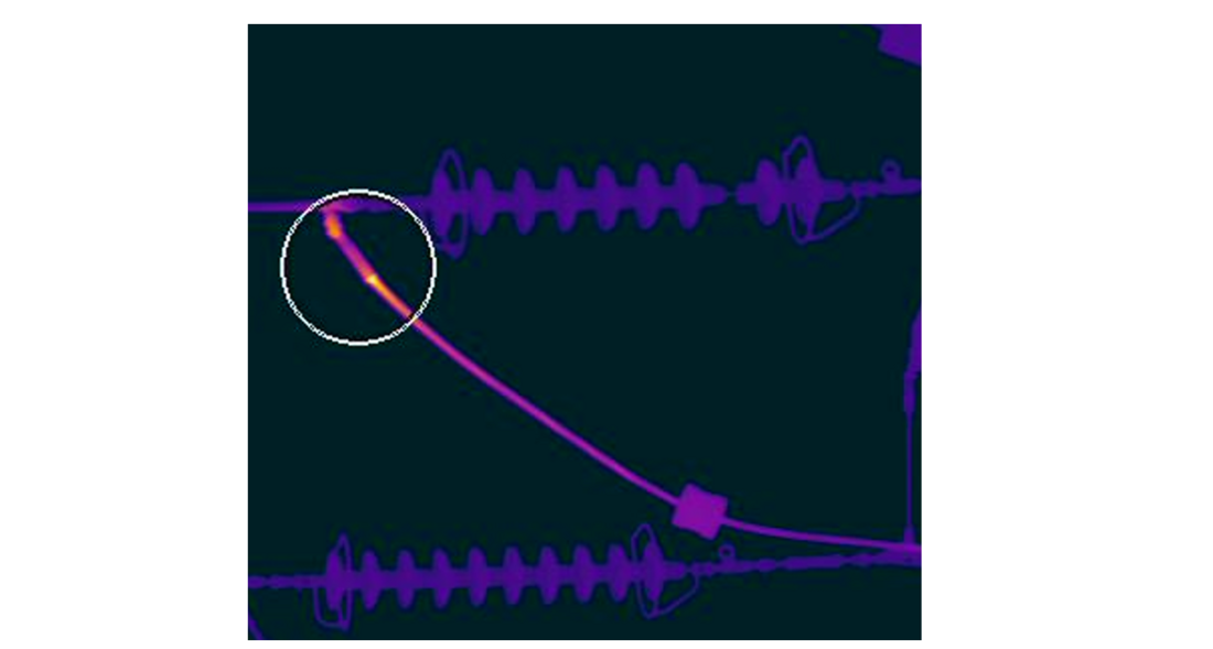
Figure 1 - Example of heating on a conductor clamp within a colour scale: -10 – 40 °C. Missing insulator glass disc is also kept in the image.
There are several different recommendations regarding the temperature criteria which can be acceptable for an insulator. Most commonly known is probably EPRI Violet book [22] and EPRI Yellow book [23]. According to these sources, a temperature difference (ΔT) of 1–3 °C between a hotspot and a reference temperature is initially indicative of potential internal damage to the insulator. It is considered that this threshold is applicable during the early stages of damage development (internal defects can be detected at lower temperature differences than that). As defect progress, the heat will be significantly higher, as shown in [24]. If the discharges erode epoxy materials in the core, the localized temperature rise can become significantly higher, potentially reaching several hundred degrees Celsius. However, the rate of heat transfer is slow, and the observed surface temperature is influenced by the location of the heat source within the insulator. Thus, even small hotspots, with a temperature difference as low as 0,5 °C, can signal critical internal damage, while more advanced damage is likely to produce surface temperature differences of several tens of degrees Celsius.
In all cases, key to accurately identifying internal defects is the comprehensive analysis of both the temperature difference and the position of the hotspot.
2.1.3. UV inspection
A UV-camera operates in the ultraviolet spectrum and will reveal corona discharges. It can reveal mostly external, but also internal issues with the insulator. Corona discharges are visible to the human eye, if severe. However, the sunlight will mask them during the day, and corona is only visible in dark laboratories or during the night. Modern daylight UV-cameras will overlay the discharges with a visual sensor pinpointing the source of discharges with good accuracy. It is a valuable tool for identifying flaws in the design of protective devices. It can also be used to find internal damages in insulators, but with lower hit rate than IR. This is due to following:
- If an internal defect causes localized degradation or carbonization of the dielectric, making it (semi-)conductive, it can distort the local electric field. This distortion may elevate the electric field at the surface of the housing material beyond the breakdown strength of air, potentially resulting in visible corona or surface discharges near the defect.
- Corona discharges are generally visible only when there is a clear line of sight, i.e. if a puncture is on the opposite side of the insulator from the operator the photons will not reach the camera sensor and visualise the discharges.
- Discharges originating from metal surfaces are significantly more intense than surface discharges on insulators. As a result, improperly positioned protective devices can obscure corona discharges caused by internal defects.
Moreover, the presence of poor electric field grading on an insulator does not guarantee the visibility of discharges in dry air. This is especially relevant when comparing observations made by UV cameras under different environmental conditions. For instance, Figure 2 illustrates how discharge visibility can vary between humid (no precipitation) and dry weather.
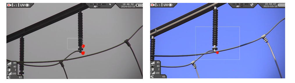
Figure 2 - Indication of poor electric field grading along insulator housing in humid weather (left), but no indication in dry weather (right). Indication of excessive electric field on conductor end in both types of weather.
2.1.4. Other technologies
In addition to well-established methods, several other technologies can be applied for the diagnostics of composite insulators, such as ultrasonic cameras and electric field measurements.
In theory an ultrasonic camera offers similar capabilities to daylight UV cameras, with the added benefit of greater flexibility since they do not require a clear line of sight to detect discharges. However, a significant limitation of current ultrasonic cameras is their typically wide field of view. This broad focus reduces their effectiveness in pinpointing discharge sources located several tens of meters away, making them more suitable for applications in low and medium voltage systems or for gas leak detection rather than for insulator diagnostics.
Electric field probes have also seen limited use in the diagnostics of composite insulators. This is rather heavy equipment to carry, particularly when climbing towers for on-site inspections. Moreover, their structural design makes it difficult to accurately evaluate electric field disturbances near HV fittings, especially when protective devices are in place. This limitation is critical, as many internal defects, often driven by electric field stress, originate close to HV fittings. Additionally, electric field diagnostics are significantly more time-consuming than other available technologies, which further limits their practical use in the field.
2.2. Application of different technologies
The diagnostic technologies discussed above can be applied from the ground, either on foot or using a ground vehicle, as well as from towers, helicopters, and drones. Ground- and helicopter-based applications are well covered in the literature [25]. More unconventional methods, such as using robots that travel along the conductors, also exist but will not be discussed further.
2.2.1. Ground
Ground inspections are often the most time-consuming type of inspection, particularly in difficult terrain. They can be conducted either on foot or using a vehicle. Since the operator can only view the object of interest from below, the likelihood of detecting deterioration or damage is slightly reduced. As a result, ground inspections may not be the preferred method for inspecting all insulators along the whole overhead line, especially in challenging terrain. However, for assessing insulators at a sample level, ground inspection remains a strong option. Due to the considerable distance, often tens of meters between the operator and the object, all sensors used must have a long focal length.
2.2.2. Helicopter
Helicopter inspection is the fastest and most versatile method for inspecting insulators along a power line. The helicopter slows down and hovers near each tower, allowing for close examination. If signs of deterioration or damage are detected, it can quickly reposition to view the tower from another angle. The helicopter's speed and range between towers far surpass those of other inspection methods. However, this efficiency comes at a high cost. The approach requires the same sensors used in ground inspections, including long focal length lenses for detailed imaging since the helicopter will be positioned tens of meters from the object of interest.
2.2.3. Drone
The use of drones has grown exponentially over the past five years, driven by advancements in battery capacity and sophisticated sensor technologies. However, national legislation still poses significant obstacles, restricting their full potential. Drones can serve as a primary inspection tool for entire overhead lines or as a complementary method when ground inspections are insufficient. Their versatility is especially notable in high-voltage environments, as they can safely operate within one meter of energized components. This proximity eliminates the need for long focal length lenses, reducing equipment complexity. While autonomous beyond-visual-line-of-sight (BVLOS) flights remain prohibited in many countries, regulatory bodies are actively exploring ways to ease restrictions and enable broader adoption of this transformative technology.
2.3. Inspection conditions
Inspections can be performed in nearly any type of weather, but certain conditions can complicate or even make analysis impossible. While no weather is ideal for inspections, it's crucial to understand the challenges different conditions present. Precipitation poses significant difficulties. It can lead to discharge activity from metal surfaces, pollution-driven discharges, water-induced corona effects, and the cooling of internal heat sources. Additionally, it reduces sensor visibility, especially for visual, UV, and most notably, infrared (IR) sensors.
2.4. Summary of inspection methods and technology
Within the established R&D Consortium a group of several European utilities and Independent Insulation Group first analysed findings obtained from literature search for modern diagnostic test methods and sensors applicable to the condition assessment of composite insulators. This is keeping in mind the dominating type of failure (flashunder) caused by weak adhesion of core/housing, and/or low quality of the core (rod), i.e. internal type of defect. Another aspect is that this type of defect will be accelerated in the presence of an electric field if it is too high; thus, it is also important to reveal this issue. The following types of diagnostic technologies were originally considered:
- IR cameras.
- UV cameras.
- Standard cameras.
- E-field probe.
- High-frequency (HF) tool.
- Acoustic methods.
One diagnostic method does not cover all types of defects that may be found in service, leading to the creation of a ranking system for various methods based on their effectiveness in detecting different flaws. This ranking evaluates three major categories: excessive electric fields along the housing (due to poor electric field grading), excessive electric fields on protective devices, and internal defects within the rod or interphase rod/housing.
The results of consideration of R&D consortium based on literature search are presented in Table 1. The traffic light rating is applied. GREEN colour illustrates that the specific application or criteria is fully applicable, suitable, or meets the desired standards with no issues. YELLOW colour illustrates that the application is somewhat acceptable, but there may be some limitations or concerns. RED colour illustrates that the application is not suitable, fails to meet essential criteria, or poses significant issues.
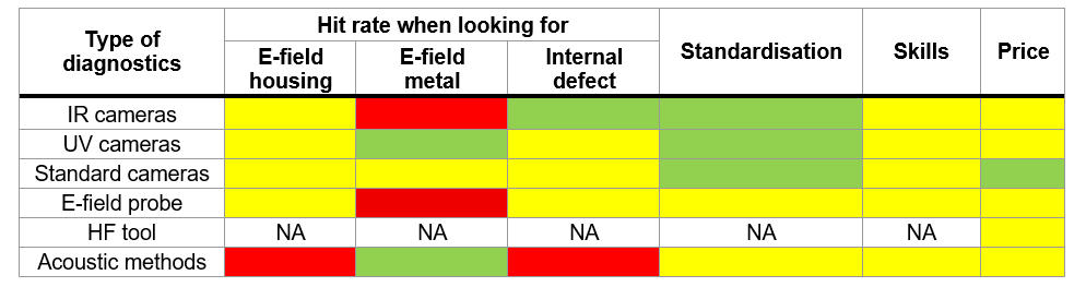
Table 1 - Diagnostics methods rated to find excessive electric field on insulator housing (E-field housing), excessive electric field on protective devices (E-field metal) and internal defects where GREEN illustrates full applicability, YELLOW acceptable applicability, and RED colour illustrates non-acceptance for specific application.
The main conclusion is that, fundamentally, diagnostic methods have not significantly changed since the first CIGRE reviews nearly 30 years ago. The most effective diagnostic approach remains a combination of infrared (IR) and ultraviolet (UV) inspections, complemented by visual assessments. This methodology was consistently applied during inspections across three different countries performed and presented in this paper. The use of an electric field (E-field) probe is not a remote process and requires physical force. Additionally, there is no practical information available regarding the use of high-frequency (HF) tools. Acoustic methods, meanwhile, are still unreliable for objective evaluations of insulators at overhead lines.
2.5. Geographical and environmental conditions
The selected inspection sites were chosen to provide a diverse range of environments, offering a comprehensive spectrum of geographical and service conditions. The insulators were examined across various pollution environments, ranging from very clean to moderately polluted areas. The sites included locations near the coast (within 1 km of the sea) and those situated far inland (up to 60 km from the coast). Inspections covered different types of seas, including the Mediterranean, Baltic Sea, and North Sea, each characterized by varying levels of water salinity. Pollution conditions varied from relatively clean and flat agricultural land to forested areas, small hills (<600 m), and industrial zones such as petrochemical factories. Site Pollution Severity (SPS) classifications according to IEC 60815 [26] were not properly evaluated but were estimated from earlier measurements in similar regions to be between SPS class 1 and 4. Some examples are shown in Figure 3 and Figure 4.
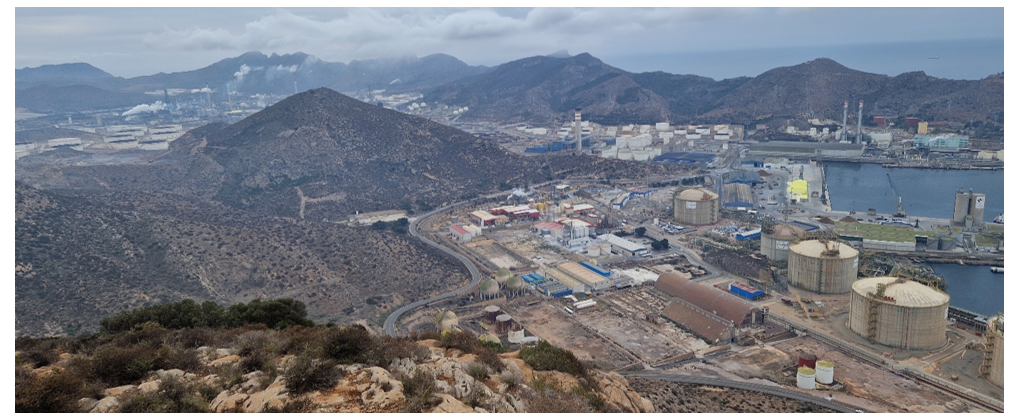
Figure 3 - Petrochemical factory close to hills and Mediterranean Sea. Transmission line goes into substation within the plant
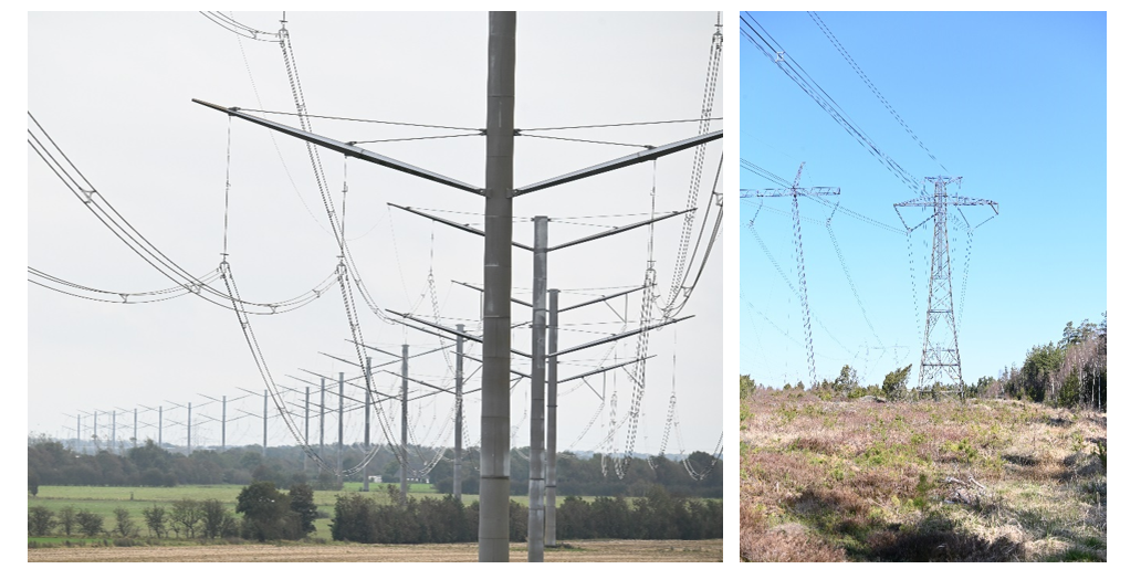
Figure 4 - Left: 420 kV double circuit transmission line in agricultural area. Right: 500 kV DC line in forest area
2.6. Insulators inspected
A wide array of insulator designs (manufacturers) and string configurations representing different voltages and mechanical classes were selected for the inspections. The chosen insulator strings for the inspections covered almost all types of configurations and both AC and DC insulators were inspected.
Based on an analysis of local service experiences, both lines with suspected poor-quality insulators and with high-quality insulators were selected.
The inspected array of insulators covered a broad variation of composite insulators for AC:
- Different voltage classes – Um 123 kV, 245 kV and 420 kV.
- Different mechanical classes – SML between 120 kN and 500 kN.
- Different time in service – between 1 and 29 years.
- Insulators from six different manufacturers.
- Different housing materials – High Temperature Vulcanized (HTV) silicone rubber, Liquid Silicone Rubber (LSR), and EPDM alloy.
- Different string configurations, including single and double suspension, double tension, V-string and insulated cross-arms.
- A total of 291 different insulator strings with a total of 563 insulators.
The inspected DC line included the following parameters of the composite insulators:
- System voltage 500 kV DC.
- SML 120 kN.
- 13 years in service.
- HTV housing material
- One design (manufacturer).
- Different string configurations, including single suspension, double tension and V-string.
- A total of 13 insulator strings and 19 insulators in total.
3. Findings
During the inspections for this project, weather conditions varied from sunny, clear skies to cloudy periods with light precipitation. Throughout all inspections, temperatures ranged from 8 to 18 degrees Celsius.
Most of the deteriorations found for almost 600 inspected insulators were of superficial character, these types typically included:
- Pollution including bird’s excrements.
- Signs of surface leakage current activity.
- Chalking (whitening of the surface).
- Biological growth.
- Minor shed bending.
- Loss of hydrophobicity to different degree.
- Traces of insects.
- Minor handling issues from installation.
- Minor corrosion of end fittings.
Biological growth was observed across several regions. The observed pattern aligns with the findings reported in [27], which indicate that biological growth is more likely to occur in cleaner environments and less likely in polluted areas. Examples of biological growth found are shown in Figure 5 and Figure 6.
Figure 5 - Biological growth on insulator housing.
Minor handling issues were also discovered, with marks on the insulators originating from the protective devices during installation, as shown in Figure 6.
A more thorough discussion of other types of deterioration will follow.
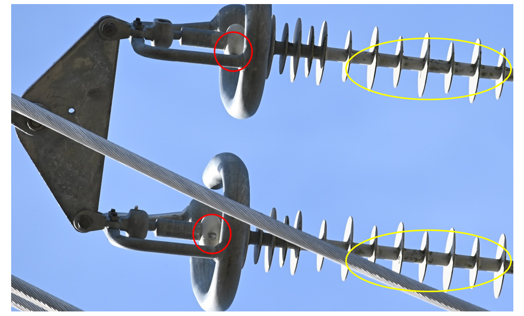
Figure 6 - Markings from handling and installation marked with red ovals. Biological growth marked with yellow ovals
3.1. Poor electrical grading
Poor electric field grading of insulators has been identified in several designs and regions, indicating a frequent lack of knowledge regarding the correct selection and installation of protective devices. In many cases, the installed grading ring failed to sufficiently shield the end fitting, resulting in an elevated electric field along the insulator housing near the HV end. Evidence of discharge activity near the HV end fittings was visible on several insulators, corroborating these findings. This activity suggests local electric field enhancement due to improper electric field grading. Two illustrative cases are shown in Figure 7. However, despite the visible signs of discharge, the electric field intensity remains below the threshold required to sustain continuous discharges in dry conditions. Consequently, no activity was detected using ultraviolet (UV) imaging techniques.
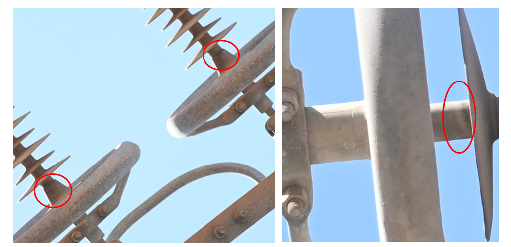
Figure 7 - Traces from discharge activity on the housing marked with red ovals
Improper installation practices or inadequate installation guidelines became evident when numerous identical insulators along the same transmission line were found to have grading rings positioned inconsistently. In several cases, the deviation in grading ring placement for identical insulators exceeded 50 mm. Such variation significantly impacts the electric field distribution along the insulator, potentially resulting in a difference of approximately 20% in electric field stress. An example illustrating the variation in grading ring positioning on identical insulators along the same line is shown in Figure 8.
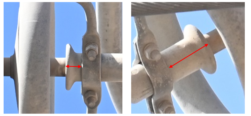
Figure 8 - Difference in grading ring positioning for identical insulators at the same transmission line causing very different electric field grading along insulators (approximately 20% difference in electric field stress). Red lines illustrate the different positions
During an inspection, it was found that the transposition tension strings operating at 123 kV lacked proper electric field grading at one end. In such configurations, the insulators are equally stressed by high voltage from both ends, making equal electric field grading essential. This is illustrated in Figure 9. This leads to an excessively high electric field along the insulators on one side. A similar issue was observed with the 420 kV transposition tension strings, where continuous discharge activity occurred at one end. This was due to inadequately dimensioned protective devices at that end, which were designed for ground potential rather than the actual potential at that location, see Figure 10 and Figure 11.
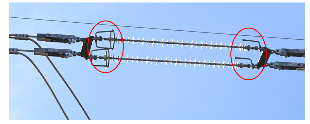
Figure 9 - Difference of protective devices at 123 kV transposition tension string marked with red ovals
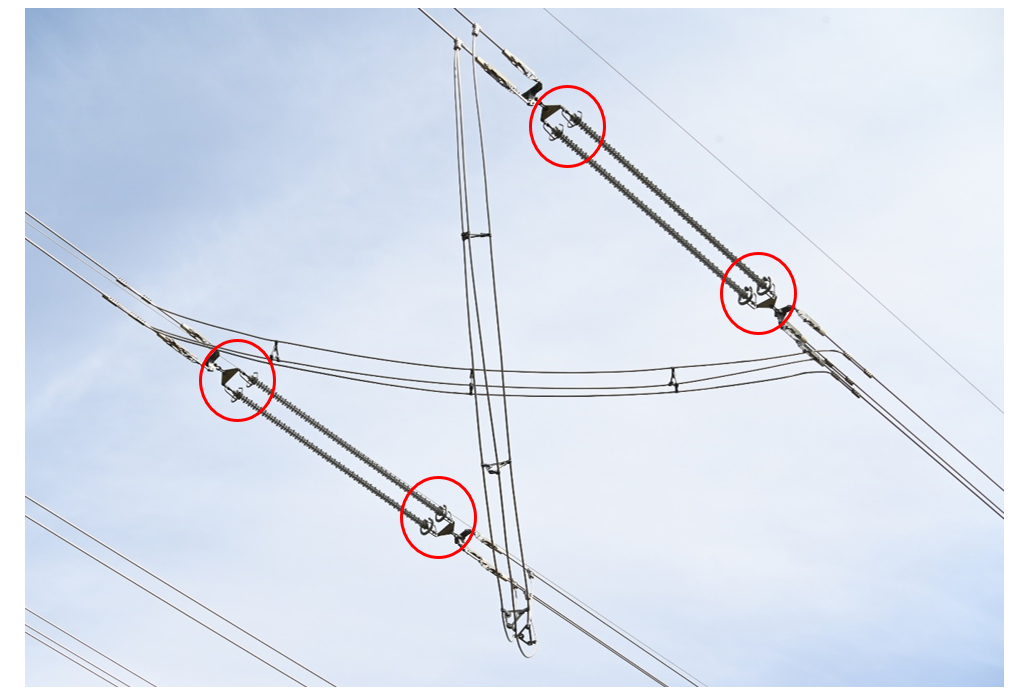
Figure 10 - Difference of protective devices at 420 kV transposition tension string marked with red ovals
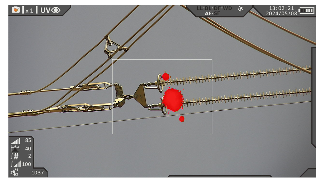
Figure 11 - Continuous discharge activity due to improper dimensioned protective devices (intended for ground potential in a 420 kV string) at 420 kV transposition tension string
Two nearly identical designs of protective devices, installed in different regions and string configurations, yielded different performance outcomes. In one case, excessive electric field stress led to continuous discharge activity, resulting in turn in material loss and roughened lower end radius, which is shown in Figure 12. This observation confirms a need for correct dimensioning of protective devices and electric field grading for each specific string configuration.
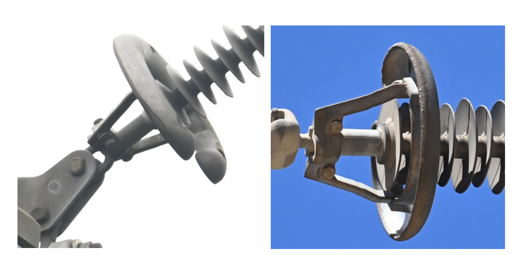
Figure 12 - Difference in ageing and appearance at the lower radius of the same type of protective device due to different positionings of the insulators resulting in lower electric fields on the lower part of the protective device in V-string (left) compared to tension string (right)
3.2. Heating
In many cases, slight heating of the AC insulators was observed, but most of the temperature gradients were attributed to solar heating (as per expert evaluation) and were considered negligible. Additionally, temperature gradients near the end fittings were observed, which were caused by radiation and reflections from nearby equipment (as per expert evaluation). Furthermore, temperature gradients near the end fittings, resulting from dielectric losses (as per expert evaluation), were also noted in several instances.
A thorough analysis of infrared (IR) results is often necessary, and it requires cross-checking with other diagnostic techniques. At one specific tower, minor heating (ΔT < 1°C) was observed near the end fitting on several insulators. This could be due to dielectric losses in the high electric field region, but it may also indicate the early onset of internal activity. Dielectric losses tend to increase in areas with high electric fields, which suggests poor electric field grading. In this case, however, the heating was spread across several sheds along the insulator, which is not typical. Normally, dielectric losses are spread to the smaller portion of the trunk of an insulator near the HV fitting, rather than extending along its entire length. Example of this is shown in Figure 13.
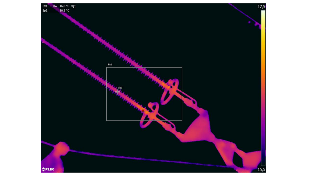
Figure 13 - Heating close to high voltage end fitting that could indicate the beginning of internal activity, colour scale: 15,5 – 17,5 °C (DT is 0,5oC)
Heating most probably related to internal activity was revealed for another insulator set. This specific inspection was performed during cloudy and humid weather with a light drizzle. The results revealed minor heating (DT 1,5 °C) which was mostly pronounced close to the high voltage end fitting and was spread up to about 10 sheds. Insulators are installed in a double circuit tower and an IR image of the insulator set compared with one of the neighbouring phases (without visible heating) is shown in Figure 14.
The analysis of UV data revealed sporadic discharge activity on a heated insulator, when compared to a neighbouring phase, see Figure 15. A second insulator from the same line was tested and failed the standard dye penetration test (according to IEC 62217) [15]. Additionally, even the insulator passed the water diffusion test (according to IEC 62217) [15] with acceptable current, even though it was remarkably high. This showed poor rod quality, suggesting that, although the insulators remain functional, the rod quality will potentially affect long-term reliability. The batch of these insulators should be IR-monitored and the insulators with observed heating should be replaced.
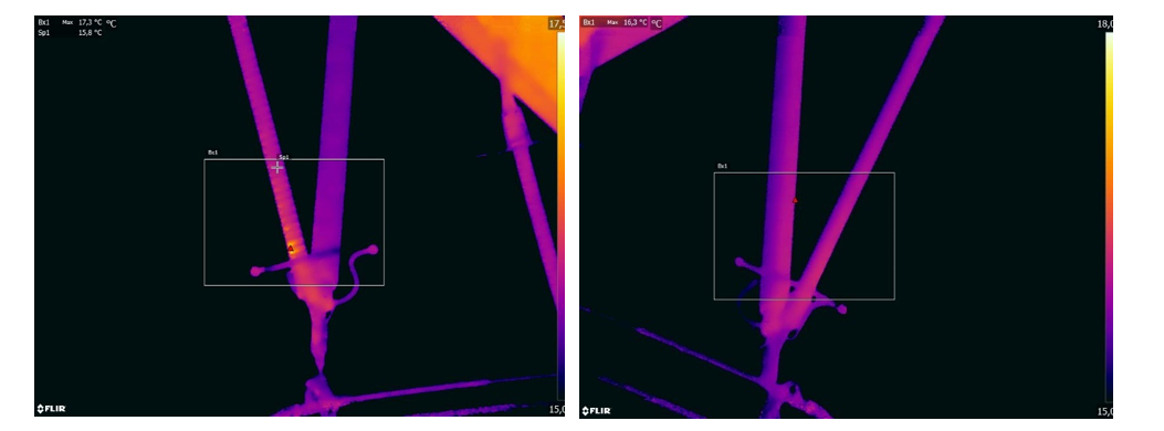
Figure 14 - Heating close to high voltage end fitting that indicate internal activity (left) compared to neighbouring insulator set (right), colour scale: 15,5 – 17,5 °C
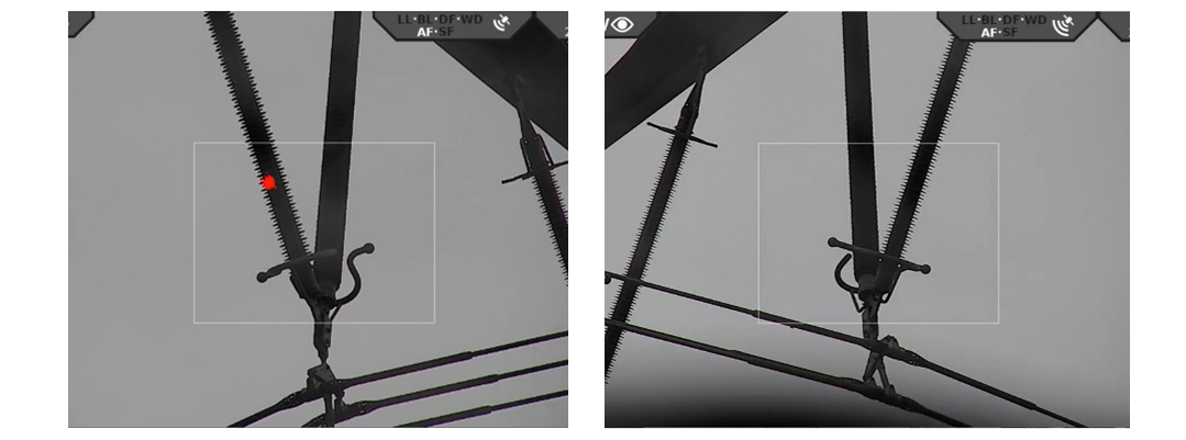
Figure 15 - Discharge activity on the housing indicating internal defect (left) compared to neighbouring insulator set (right)
Known service experience from one of the overhead lines, where several insulator failures occurred, triggered the inspection of insulators from the same batch installed on another line. These were approximately 30-year-old insulators. The previously removed insulators (from the other line) had been tested and were found to exhibit poor quality in both the rod material and the interface between the rod and the housing. These samples failed both the water diffusion test and the dye penetration test, as standardized in IEC 62217 [15]. On the inspected line, the insulators were installed as V-string sets to support the jumper loop at tension towers. For all 44 inspected insulators, the temperature difference (ΔT) exceeded 1 °C. The ΔT values ranged between 1 °C and 7 °C, indicating internal damage affecting between 8% and 23% of the insulating length. One IR image is shown as an example in Figure 16.
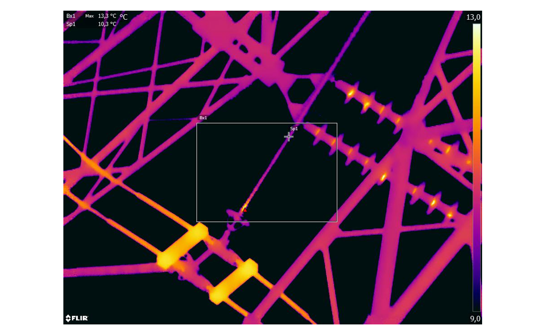
Figure 16 - Heating close to high voltage end fitting that indicate internal activity, colour scale: 9 – 13 °C (ΔT 3 oC)
All inspected DC insulators seemed to be in good condition. No visual deterioration or indications with either UV- or IR-camera were revealed.
4. Lessons learned
The dominant type of more recent failures of composite insulators is a flashunder, i.e. internal breakdown either in the interface core/housing or in the rod itself. This failure is caused by manufacturing defects (poor quality control of the interface or the rod), which would be accelerated excessively if exposed to a high electric field (due to design weakness in the form of improper design of grading rings).
The literature search performed by the R&D consortium for mostly internal type of deterioration resulted in the consideration that the most optimal diagnostic methods are a combination of IR and UV combined with visual inspections. This approach was followed during the inspections in three different countries. These inspections covered about 600 AC and DC composite insulators ranging from 123 kV up to 500 kV operated up to 30 years in light to medium pollution environments. Most of the inspected insulators were in good condition and their deterioration was of superficial character, characterized by signs of discharge activity, biological growth, chalking, few installation issues, etc.
At the same time, the performed inspections revealed a lack of knowledge regarding the optimal design of grading rings. This was revealed by a combination of visual and UV techniques. The same grading rings were installed on identical insulators differently, which would result in 20% difference in electric field strength along the housing. Transposition insulator strings were properly protected only from one end. This results in both too high electric field on the protective devices causing continuous discharge activity, deterioration of the hardware and audible noise. This also results in excessively high electric field stresses along the composite insulator housing causing deterioration and premature ageing. Too high electric field stresses were common even for insulators installed relatively recently. This will lead to water induced corona, which is not a severe deterioration, but will contribute to ageing in lightly polluted areas. The electric field issues require proper calculations considering the specific insulator string configuration and modern requirements for the limitation of electrical stress recently published in the revised version of IEC 61109 [14].
The inspections revealed internal issues in an entire batch of insulators, which was anticipated. Additionally, they identified internal defects in a specific insulator where such issues were not expected. Subsequent investigations after removal of insulators from service confirmed that the rod in this specific insulator was of poor quality.
In some instances, the UV camera also detected inadequate corona protection of the hardware. Furthermore, it revealed poorly designed protective devices that were contributing to audible noise and continuous discharge activity.
For the utilities involved in this project, these inspections provided valuable insights for future requirements on installations, future assessments, the interpretation of inspection data, and maintenance planning.
References
- I. Gutman, A. Deckwerth, K. Halsan, M. Leonhardsberger, P. Meyer, L. Diaz, M. Radosavljevic, P. Trenz, K. Varli, K. Välimaa: “Application of Composite Insulators: Perceptions vs. Service Experience”, 2022 INMR World Congress, Berlin, Germany, 16-19 October 2022.
- Xidong Liang, Weining Bao, Yanfeng Gao, Shaohua Li, I. Gutman, C. Ahlholm, M. Radosavljevic, W. Vosloo, “A new type of failure of composite insulators: service experience, degradation characteristics, root cause, experimental simulation and countermeasures”, CIGRE-2020, D1-207.
- I. Gutman, C. Ahlrot, P. Aparicio, A. Berlin, T. Condon, A. Dernfalk, J.-F. Goffinet, K. Halsan, K. Kleinekorte, J. Lundengård, M. Radosavljevic, P. Sidenvall, S. Steevens, K. Varli, K. Välimaa: “Development of Innovative Test Procedure for Evaluation of Adhesion of Core-Housing of Composite Insulators: from Root Cause of Failures in Service to Reproducible Test Procedure”, CIGRE Science & Engineering, N. 20, February 2021, p.p. 171-182
- I. Gutman, A. Dernfalk, J. Lundengård, P. Sidenvall, A. Deckwerth, L. Diaz, K. Halsan, M. Leonhardsberger, M. Radosavljevic, P. Trenz, K. Varli, K. Välimaa: “Test methods and criteria for validation of functional properties of composite insulators related to materials and interfaces”, CIGRE 2022, Ref. D1-10828_2022.
- I. Gutman, A. Dernfalk, P. Sidenvall, J. Lundengård, C. Ahlrot, P. Aparicio, A. Berlin, T. Condon, J.-F. Goffinet, K. Halsan, R. Radosavljevic, K. Varli, K. Välimaa, “Rod to Housing Adhesion in Composite Insulators: Practical Evaluation in Collaboration with Utilities", 2019 INMR World Congress, Tucson, USA, 20-23 October 2019.
- I. Gutman, P. Sidenvall, T. Condon, P. Flynn, P. Shiel, “Evaluation of composite insulators with internal deterioration: lessons learned from service and after-service testing”, CIGRE Winnipeg 2017 International Colloquium & Exhibition, Winnipeg, Canada, September 30 - October 6, 2017, paper 142. - ref. COLL_WIN_2017
- I. Gutman, A. Dernfalk, P. Sidenvall, J. Lundengård, “New Test to Reveal Level of Rod/Housing Adhesion for Composite Insulators”, 21st ISH-2019, Budapest, Hungary, August 26-30, 2019, paper 749.
- A. Dernfalk, P. Sidenvall, I. Gutman, “Development of the test capable to reveal level of adhesion between fibreglass rod and housing of composite insulators”, CIGRE-IEC 2019 Conference on EHV and UHV, April 23-26, 2019, Hakodate, Hokkaido, Japan, P1-10, Ref. COLL_HAK_2019.
- C. Ahlrot, P. Aparicio, A. Berlin, T. Condon, J.-F. Goffinet, I. Gutman, K. Halsan, M. Radosavljevic, K. Varli, K. Välimaa, “New test procedure intended to evaluate adhesion of core/housing interface of composite insulators”, CIGRE-2020, D1-303_2020.
- A.J. Philips, A.J. Maxwell, C.S. Engelbrecht, I. Gutman: “Electric Field Limits for the Design of Grading Rings for Composite Line Insulators”, IEEE Transactions on Power Delivery, Vol. 30, No. 3, June 2015, p.p. 1110-1118.
- I. Gutman, P. Sidenvall: “Optimal Dimensioning of Corona/Grading Rings for Composite Insulators: Calculations & Verification by Testing”, World Congress & Exhibition on Insulators, Arresters & Bushings, Munich, Germany, 18-21 October 2015.
- P. Sidenvall, I. Gutman, A. Deckwerth, L. Diaz, P. Meyer, J.F. Goffinet, K. Halsan, M. Leonhardsberger, M. Radosavljevic, P. Trenz, K. Varli, K. Välimaa: “Limits of electrical field for composite insulators: state-of-the art and recent investigations of insulators purchased by power utilities”, CIGRE Science & Engineering, N. 24, February 2022, p.p. 1-14.
- M. Jalonen, K. Välimaa, I. Gutman, A. Deckwerth, K. Halsan, M. Leonhardsberger, L. Diaz, P. Trenz, K. Varli: “Benchmarking Composite Insulators: Utility Perspective & European Initiative”, 2023 INMR World Congress, Bangkok, Thailand, 12-15 November 2023
- IEC Standard: “Insulators for overhead lines – Composite suspension and tension insulators for a.c. systems with a nominal voltage greater than 1 000 V – Definitions, test methods and acceptance criteria”, IEC 61109 Edition 3.0, 2025.
- IEC Standard: “Polymeric HV insulators for indoor and outdoor use – General definitions, test methods and acceptance criteria”, IEC 62217 Edition 3.0.
- CIGRE WG B2.57: “Experience with and application guide for composite line insulators”, CIGRE TB 919, November 2023.
- I. Gutman, J. Lundengård, P. Sidenvall, A. Deckwerth, L. Diaz, J.F. Goffinet, K. Halsan, M. Leonhardsberger, M. Radosavljevic, P. Trenz, K. Varli, K. Välimaa, M. Heath, R Davey, W. Vosloo: “Condition assessment of line composite insulators: after-service test programs and their practical application”, CIGRE Science & Engineering, N. 28, March 2023, p.p. 1-37.
- CIGRE WG B2.21: “Assessment of in-service Composite Insulators by using Diagnostics Tools”, CIGRE TB 545, August 2013.
- CIGRE WG B2.21: “Guide for the assessment of Composite Insulators in the Laboratory after their Removal from Service”, CIGRE TB 481, December 2011.
- STRI Guide: “Guide for Visual Identification of Deterioration & Damages on Suspension Composite Insulators”, STRI Guide 5, 2005.
- EPRI field guide: “Visual inspections of polymer insulators”, ID 3002005627, 2015.
- EPRI Violet book: “Insulator Reference Book”, ID 3002010140, December 2017.
- EPRI Yellow book: “Overhead Transmission Inspection and Assessment Guidelines – 2006”, ID 1012310, 4th edition, November 2006.
- P. Sidenvall, A. Sandoval, A. Taheri, J. Remelin: ”New competencies and diagnostic methods needed for the application of composite insulators in substations,” CIGRE Session, Paris, France 2024, Ref. B3-10795-2024
- I. Gutman: "Helicopter & Ground-Based Methodologies to Detect Damaged Insulators", World Congress & Exhibition on Insulators, Arresters & Bushings, Seoul, Korea, 17-20 April 2011
- IEC Technical Specification: “Selection and dimensioning of high-voltage insulators intended for use in polluted conditions – Part 1: Definitions, information and general principles”, IEC TS 60815-1 Edition 1.0, 2008-10.
- I. Gutman, A. Dernfalk, V. Malinen, M. Radosavljevic, K. Varli: “Critical review on biological growth on composite insulators in northern and central European environments: evaluation of risk for pollution flashover and ageing”, CIGRE Science & Engineering, N. 22, October 2021, p.p. 1-28.