Power utility perspective on composite insulator condition and end-of-life assessment – Part 1
Authors
F. JOOSTE, R. DAVEY, D. MVAYO - Research Testing and Development, Eskom Holdings SOC Ltd, Cape Town, South Africa
W. VOSLOO - Retired

Summary
Composite insulators may be subjected to various harmful environmental conditions, such as high levels of pollution (marine, industrial and sugar cane), recurrent wetting cycles and ultraviolet exposure, to name a few. Early detection of damage or material degradation on composite insulators is critical, as it could ultimately lead to failure, including outages or even loss of life. Utilities face the challenge of finding a proactive and objective approach to determine the condition and life expectancy of in-service composite insulators. Composite insulator condition and end-of-life assessment is a complex task that requires a multi-faceted approach and cannot be achieved through general observations of these insulators.
This two-part paper explores two in-service composite insulator end-of-life assessment approaches. A comprehensive approach and a practical approach, both of which have been defined based on the end-of-life criteria, namely mechanical, electrical, and loss of pollution performance.
In Part 1 of this two-part paper, the condition assessment, operational lifespan, service experience and selection approaches of high-voltage outdoor composite insulators are reviewed.
Part 2 utilises the above to define two in-service composite insulator end-of-life assessment approaches, a comprehensive and a practical approach, which have both been defined based on the end-of-life criteria, namely mechanical, electrical and loss of pollution performance.
Keywords
Composite insulator, condition assessment, end-of-life, lifespan, pollution1. Introduction
The reliability of a power system can be significantly influenced by the selection and performance of high-voltage insulators. Both the selection process and performance are affected by the prevailing electrical, mechanical, environmental, and climatic conditions. If insulators are incorrectly selected during the line or substation design phase, environmental and climatic conditions may negatively affect their pollution performance when they are critically polluted and wetted. Effects of ageing can result in significant changes to the surface properties of composite insulators, which may be permanent in some cases and can ultimately lead to electrical and/or mechanical failure.
During the selection and dimensioning process, whether for new build or refurbishment projects where composite insulators will be used, it is important to understand the initial requirements as dictated by the site itself (IEC/TS 60815-1 [1]), the technical application thereof (IEC/TS 60815-3 [2]) and for a broader view of technical aspects, CIGRE TB 158 [3], CIGRE TB 361 [4] and the newly published CIGRE TB 919 [5].
Utilities face the challenge of finding a proactive and objective approach to determine the condition and life expectancy of in-service composite insulators. Traditionally, insulator field failures are investigated retroactively, and only then can appropriate actions, such as replacement, be taken. Various internationally recognised practices, such as visual inspections and ultraviolet/infrared (UV/IR) scanning, are widely used to determine the condition of insulators. However, these processes are somewhat subjective, as they depend on the time of assessment and the operator's experience.
This two-part paper aims to provide different methods for conducting condition and end-of-life assessment of composite insulators by outlining common modes of insulator failures and highlighting the areas that should be closely monitored. Two condition and end-of-life assessment approaches will be defined, namely a comprehensive and a more practical method.
In order to compile this multi-faceted proactive approach to composite insulator condition assessment, various topics must be considered, including maintenance and condition assessment best practices, known failure modes, as well as insulator selection and dimensioning for specific applications.
2. Composite Insulator Lifespan
This section investigates the factors that determine and influence the lifespan of composite insulators. It then examines a method for selecting insulators with a required lifespan in mind.
It is believed that by understanding the factors which influence the lifespan of composite insulators, line designers can select and apply composite insulators more effectively, and together with a multi-faceted proactive approach to in-service condition assessment, will result in reduced lifecycle and maintenance costs.
2.1. Overview of composite insulator lifespan
The term ‘composite’ refers to insulators which possess a glass fibre reinforced plastic/epoxy resin rod (FRP) (provides mechanical strength) covered by a housing material, generally silicone-based, to protect the core from the environment and to provide the required electrical characteristics [6]. While composite insulators have certain advantages over traditional ceramic insulator materials, such as improved pollution performance, these insulators are, however, susceptible to material ageing effects.
The lifespan of composite insulators is not limited to insulation failures due to pollution build-up or degradation caused by tracking and erosion. Its long-term in-service performance is dependent on the exposure of the overall and local electrical stress, whose value, duration and position depend on the pollution level, wetting (cycles), hydrophobicity loss and recovery, including the insulator profile [2]. Once the electrical stress reaches a critical level, it can lead to either flashover due to insufficient creepage distance or local erosion or tracking, which can lead to other failure mechanisms.
In order to define composite insulator end-of-life, it is necessary to understand terms such as “lifespan” and “residual lifespan” of these insulators. Various literature sources demonstrate that operationally, the practical expected lifespan of composite insulators varies considerably:
- Existing operating experience shows that the lifespan of composite insulators is between 15 and 20 years [7].
- Composite insulators have a general average lifetime in the range of 10-15 years [8].
- Through a combination of accelerated ageing tests and ageing data from field insulators, EPRI predicted that the composite insulators evaluated are expected to perform satisfactorily for 30 years [9].
- An earlier report from EPRI stated that, even though composite insulators had been in operation for just over 20 years at the time, the expected service life of composite insulators was still unknown [10].
- In [5] useful lifetime was determined to be approximately 20 years for 230 kV and lower voltage applications and 10 to 15 years for 380 kV and above.
- With regards to composite overhead line insulators, in a survey linked to the operation of about 9 million insulators, the average time in service was found to be 24 years, with a maximum of 40 years [11], [12].
- South African experience and field failure investigations have shown that composite insulators are expected to have a minimum service life of between 20 and 25 years for sub-transmission voltages.
It is evident that an expected fixed lifespan is not easily definable by the number of years in service, but is determined by a combination of factors, as stated in [2]. However, useful lifetime is defined as a safe and trouble-free operational life in [5] and the effective residual lifespan (ERL) is defined as the duration from the present to the time of failure in accordance with current operating conditions [13].
Literature indicates that visual inspections are key to the successful evaluation of insulators [14] and for reasons of simplicity, the following criteria are typically considered to constitute the “end-of-life” of an insulator:
- Any traces and stages of brittle fracture [15] or its initiation (early stage) [16].
- Heavily corroded metal end-fittings, weak zinc coating thickness (lower than specified in [17]), heavy traces of local zinc loss and metal end fittings with extended power arc roots resulting in total loss of galvanising coating.
- Deep erosion on the housing that has already reached the FRP core.
- Defective sealing system(s).
- Housing damage due to transportation and handling, which results in exposure of the FRP core material.
- Damaged sheds in high temperature and humidity regions, as it leads to loss of creepage distance and an increased risk of pollution flashover [13].
- The insulator cannot withstand the operational mechanical load or the electrical stress [14].
It is important to have a procedure or plan in place on how to identify composite insulators for end-of-life assessment. Routine line inspections consisting of visuals, by means of binoculars, long lens cameras, remotely piloted aircraft system (RPAS) or helicopters, can identify damaged or failed insulators. UV and IR scans are also useful to identify signs of internal degradation, punctures or possible signs of moisture ingress, which could trigger the removal of insulators for further inspection.
Keeping track of power system performance, such as line faults and failure rates of various types and brands of insulators, also assists in determining failure modes specific to design and manufacturing processes. It is important to note that historical failure statistics are only useful when comprehensive maintenance and service records are kept.
From a removal and transportation perspective, it is essential that composite insulators are removed as carefully as practically possible. This is to ensure that the pollution layer on the insulator is preserved. It is also important not to disturb or cause further damage to the insulation material, for example, causing rope burning marks when lowering these insulators to ground level. Longer insulators can be cut in half to make transportation easier, while making sure to mark and tag pieces carefully. Furthermore, care must be taken not to cut in areas where damage has occurred, such as areas with tracking, erosion and punctures.
2.2. Factors influencing composite insulator lifespan
The main advantage of composite insulators is their superior performance in polluted environments compared to ceramic or glass insulators of equal creepage length. It is worth noting that some composite materials used may collect more pollution than their ceramic or glass counterparts due to their surface characteristics. Their in-service lifespan is greatly influenced by how the housing material can withstand electrical and environmental stresses, especially in heavily polluted environments, as well as the long-term integrity of the seal at the housing/rod/end-fitting interface.
Current best practices compel the use of housing materials made from polymers such as silicone rubbers based on dimethyl siloxane, cross-linked polyolefins such as EPDM rubber, or semi-crystalline ethylene copolymers, such as ethylene-vinyl acetate (EVA), or rigid highly cross-linked epoxy resins based on cycloaliphatic components [2]. However, these materials are susceptible to material degradation due to interaction with the applied electrical and environmental stresses, which are addressed by using additive packages, which include anti-tracking agents, UV screens and stabilisers, to name a few [2].
Their improved pollution performance stems from the following properties [2]:
- Smaller average diameter, notably in the case of suspension insulators.
- Reduced material thickness, which results in improved, more open profiles.
- Reduced thermal lag, which translates into less wetting due to dew/mist and altered pollution accumulation and arc propagation.
- Decreased surface conductance and leakage current activity due to the material’s hydrophobic properties.
Due to their improved pollution performance, it may be tempting to use composite insulators at a reduced creepage distance, which provides a similar pollution performance to longer creepage distance ceramic/glass insulators [2]. However, this practice reduces the long-term pollution performance and expected in-service lifespan.
In general:
- Reduced creepage distance may, in certain site conditions, result in increased discharge activity and negate any advantage in pollution performance if hydrophobicity is completely lost, and in some instances, may lead to flashover or material degradation [2]. Therefore, it is advisable to use the same creepage distance as recommended for porcelain and glass insulators in similar applications.
- The pollution performance of composite insulators made from hydrophobic transfer materials (HTM) is less influenced by diameter and air density changes. However, this influence may increase if the surface becomes hydrophilic [2].
- Excessively long creepage distance profiles, with the aim of countering extreme pollution conditions, follow the law of diminishing returns. As the complexity of the profile increases, more pollution accumulates, and less pollution is washed off. As neighbouring sheds get closer together, the local electrical field increases, resulting in dry-band arcing and shed-to-shed breakdown, hence reducing the withstand performance [2].
- The use of grading rings is necessary for voltages of 132 kV and above [18].
2.3. Composite insulator selection for required lifespan
IEC/TS 60815-1 [1] recommends three approaches for selecting and dimensioning insulators based on system requirements and environmental conditions. An overview of the data and decisions required for these approaches is shown in Table 1.
The choice of which approach to follow depends on the available data, time and budget. The three approaches also have varying degrees of confidence with regard to the performance of the type and size of the insulator that was selected.
| Approach 1 (Past Experience) | Approach 2 (Measure and Test) | Approach 3 (Measure and Design) | |
Representation of the dynamic interaction between the environment and the insulator |
|
|
|
Methodology |
|
|
|
Selection process |
|
|
|
Advantages |
|
|
|
Limitations |
|
|
|
Approach 1 (Past Experience) depends on data available from an operational line, substation or test station in the vicinity or located in a similar environment. If long-term historical insulator performance data is available from a nearby overhead line or substation, insulators can be selected that will provide a similar in-service performance.
Approach 2 (Measure and Test) follows a process of obtaining the site pollution severity, selecting candidate insulators that can possibly meet the requirements, and performing laboratory testing on the selected candidate insulators to obtain their pollution performance for the measured site pollution severity levels. With Approach 2, the statistical approach can be used to obtain a mean time between flashover (MTBF) value of the candidate insulators.
The statistical approach requires accurate measurements of the site pollution severity (at least 12 months of measurement data [1]), as well as the insulators’ flashover performance. For HTM composite or polymeric insulators, MTBF should preferably be determined for the insulator when it is hydrophobic and hydrophilic. Software is available to perform the statistical selection and dimensioning of insulators. This software can be used to determine the creepage distance of the selected insulators for a specific pollution environment and a required MTBF or lifespan.
Approach 3 (Measure and Design) also requires that the site pollution severity levels be measured or estimated. From there, the recommendations in IEC/TS 60815-3 [2] are used to determine the unified specific creepage distance (USCD) for the obtained pollution level. Further recommendations, together with correction factors, are applied depending on the material and size of the insulator to obtain the final USCD [2].
The following summarised high-level approach can be used to appropriately select insulation of substations and overhead lines:
- Follow Approaches 1 and 2 as per IEC/TS 60815-1.
- Conduct on-site pollution measurements to determine site pollution severity (SPS) class as per IEC/TS 60815-1 (minimum 12-month cycle).
- Use insulator pollution test station experience for the selection of material and creepage distance.
- Follow IEC/TS 60815-3 for composite insulators to determine the reference unified specific creepage distance (RUSCD) (see Figure 1).
- Apply relevant correction factors as per IEC/TS 60815-2 / IEC/TS 60815-3 to the RUSCD to obtain appropriate USCD for confirmation testing to be done in a laboratory.
- Alternatively, software can be used to optimally select insulator creepage distance for a site pollution severity level and performance requirement.
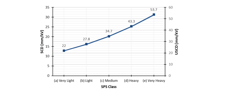
Figure 1 - RUSCD as a function of SPS class [2]
3. Composite insulators - Service experience
This section reviews both international and South African composite insulator in-service experience.
3.1. Review of composite insulator in-service experience
As with any other power system component, composite insulator performance is based on design parameters which dictate its failure rate. Composite insulators not only need to withstand normal operating voltage, but also the effects of SPS, which may lead to premature ageing and degradation of the insulator material. The failure rate varies over its life cycle, which can be defined as follows:
- Early failure period: A small percentage of equipment fails very early in its life and can usually be attributed to incorrect specifications and application, poor manufacturing quality control measures, incorrect installation practices and improper usage/handling.
- Useful life period: It is expected that equipment failure rates are constant over its useful life and are affected by both maintenance and operations practices, which must maintain performance and maximise useful life at an acceptable performance level. Incorrect or inadequate specifications, poor manufacturing quality control measures, and incorrect selection and application practices are all factors that influence the ability to achieve and maintain acceptable failure rates over the course of its useful service life.
- End-of-life: Equipment performance and condition have deteriorated beyond the maintenance regime’s capability. Mitigation strategies include refurbishment and replacement, which must be completed before its performance deteriorates unacceptably.
Experience has shown that insulator failure rates correlate well with the fluctuation of environmental and climatic conditions, with good service experience achieved when the design parameters exceed the operating condition requirements [19].
Statistics from large polymer insulator markets have shown relatively high failure rates regardless of the design [20], [21], [22]. The reports show that key parameters that affect longevity include seals, interface areas and the chemistry of the housing material itself. The limitation of these statistics, however, is that they focus primarily on designs implemented from the 1980s and 1990s (i.e. 15 to 20 years of service up to 2010) when polymer insulator design and specifications were not as well developed and standardised. The statistics indicate that for the earlier generation composite insulators, many of the failures occurred relatively early in operational life.
These statistics also show a marked decrease in failure rates from 2007 onwards, which correlates with work done at the Koeberg insulator pollution test station (KIPTS) located in the Western Cape, South Africa, as shown in Figure 2 [18]. The large increase in failures during the 2010/2011 test cycle can be attributed to products tested from various new manufacturers who wanted to enter the South African insulator market and new prototype designs and materials from established manufacturers.
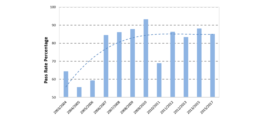
Figure 2 - KIPTS insulator test pass rate from 2004 to 2017 [18]
CIGRE [4] summarises operational experience and failure modes for composite insulators as follows:
- The performance of polymeric insulators is excellent if they have been properly dimensioned and when the correct materials are used.
- Failure of polymeric insulators using silicone rubber for the sheath and shed material is usually mechanical because of damage to the reinforced glass fibre core. It is important, therefore, to design the insulator so that the integrity of the material covering the core is maintained under all operating conditions.
- The pollution flashover performance of some polymeric materials – especially silicone rubber – is generally superior to that of glass or porcelain. In contrast, epoxy resin rapidly degrades from its new – hydrophobic – condition such that its flashover strength can be somewhat inferior to that of ceramic materials.
- Some types of discharge activity (e.g. corona or sparking) at or near the surface may cause severe degradation of the material, thereby exposing the core to mechanical degradation and also reducing the flashover performance. Such discharges may be minimised or prevented by having the correct design of stress release ring [18].
The above findings correlate with those of a more recent European survey [5], [23], which primarily focused on overhead line composite insulators, collected service experience from both in storage and removed from service insulators, with the intention to benchmark the performance of said units. This survey considered approximately 8.6 million composite insulators of which 22% were rated for use over 100 kV.
A breakdown of the leading failure modes for the insulators used in voltage applications over 100 kV is shown in Figure 3. The two failure modes highlighted in red are often confused with each other because they can occur independently or as a combination of both.
It is evident that most of the identified failure modes can be identified by means of visual inspection through an experienced operator. The extent of surface degradation, punctures and root cause of flashunder may however require specialist knowledge. The survey results infer that flashover and surface degradation mechanisms must be considered during the selection and design process of composite insulators, including their protection devices to minimise corona inception and arc root deviation for power frequency faults.
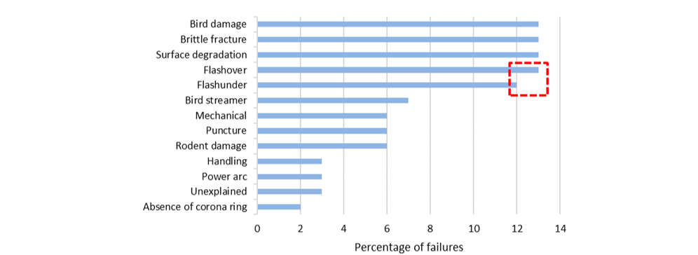
Figure 3 - Failure modes in percentage for overhead line applications over 100 kV [6]
A Chinese study sampled 371 composite insulators from lines located in high temperature and humidity regions which have been in operation for between 3 and 22 years [13]. Qualitative and quantitative analysis methods were used to assess factors contributing to ageing and ERL.
With a rise in operational life, a correlation analysis showed an increase in the following:
- Colour difference between the upper surface and deep layer a of silicone rubber.
- Material porosity (the molecular chain inside silicone rubber would rupture under prolonged UV radiation or electrical field exposure).
- Material hardness.
In turn, the following decreased with an increase in operational life:
- Artificial pollution flashover voltage due to cracks on insulator surface and sheds which decrease the effective creepage distance.
- Tensile strength and elongation of silicone rubber (high temperature and oxygen would cause oxidation and thermolysis and the CH3 side chain in the silicone rubber might be damaged).
- Mechanical failing load of the core.
- Non-polar molecule content (HCH3) of silicone rubber through FTIR analysis.
In summary, the study indicated that shed damage leading to a decreased creepage distance and heightened risk of pollution flashover was the main reason to retire composite insulators. It further noted that for insulators used in high temperature and humidity areas, when operational life exceeded 14.6 years, silicone rubber was likely to show cracks and degradation, and when operational life exceeded 18.6 years, pollution flashover would occur on these insulators during some extreme conditions, and they should be replaced gradually.
A second Chinese study examined the ageing of composite insulators that have been in service between 0 and 30 years in a coastal multi-haze environment by means of Fourier transform infrared (FTIR) spectroscopy and water diffusion tests [24].
FTIR spectroscopy analysis of the samples revealed a decrease in absorption peak areas of Si-O-Si and CH3 (similar finding to the first study [13]) with a varying increase in service life:
- From 6 to 9 years, the ageing process of composite insulators is slow.
- From 9 to 18 years, the ageing process of composite insulators is very rapid. It can be concluded that in the multi-haze environment in coastal areas, the molecular structure of silicone rubber insulators will change rapidly during this period.
- From 18 to 25 years, the ageing trend curve tends to be slow and stable.
Water diffusion tests highlighted the negative impact of prolonged service life on the integrity and performance of insulator interfaces, such as between the housing and the core and end-fitting seals.
A Peruvian case study [25] documenting composite insulator performance in coastal, mountainous and forest environments recommended the following to successfully apply these insulators:
- Select creepage distance suitable for areas with extra high site pollution severity (e.g. coastal areas).
- Polymeric material must be UV stable for high levels of radiation and withstand high currents from atmospheric discharges.
- Fibreglass cores and seals must withstand high electromechanical demands.
Based on service experience with composite insulators in Peru, the lifespan of the insulators installed on transmission lines across its different geo-climatic conditions can be estimated as:
- Coastal zones: 4-12 years.
- Jungle and mountain areas: 15-20 years.
4. Composite insulators - Condition assessment and failure modes
Composite insulator condition assessment, whether done on in-service or after-service insulators is a key aspect in determining whether an insulator has potentially reached the end of its service life. This section examines which composite insulator failure modes constitutes end-of-life from an operational perspective whereafter a high-level composite insulator condition assessment approach is described.
4.1. Purpose of composite insulator condition assessment
Some common reasons to evaluate the condition of in-service composite insulators include [14]:
- To provide an indication of life expectancy, and therefore to determine whether to leave the insulators in service or to take any countermeasures such as removal from the power system, i.e. identification of high-risk units.
- To determine the required inspection frequency.
- To identify whether modifications are required after installation, i.e. a new pollution map becomes available, electric field grading rings are required or a need for power arc protection arises.
The overall condition and ageing mode play a significant role when determining the residual service-life for in-service composite insulators. Visual guides, e.g. [6], [26], [27], are internationally used to identify various insulator damage and failure mechanisms. Insulators may be subjected to various damaging environmental conditions which may include elevated levels of pollution (marine, industrial and sugar cane), recurrent wetting cycles and UV exposure to name a few.
Other failure causing mechanisms include:
- Inferior material formulations and insulator designs.
- Inadequate manufacturing processes or quality control.
- Abnormal operating electrical or mechanical stresses.
- Improper maintenance practices.
- Mishandling of insulators during transportation and installation.
Extensive field experience and knowledge gained through numerous insulator field failure investigations and natural insulator ageing test stations within South Africa have resulted in a good understanding of the performance and failure modes of high voltage insulators in various environments and has highlighted that certain defects and ageing modes of composite insulators will result in either electrical or mechanical failure.
4.2. Composite insulator defects and failure modes
It is important to acknowledge that the in-service reliability of composite insulators has been improved through generational changes in the technologies used. Early designs depicted as 1st and 2nd generation of composite insulators have shown poor in-service performance. Newer generation three composite insulators (also referred to as “current” designs) have been successfully designed and type-tested in accordance with IEC 61109 [28] (now superseded by Edition 3, published in 2025) and have shown significantly improved in-service performance, which has been verified by tests performed at KIPTS (see Figure 2) where a step change in performance is visible for designs from 2007 onwards.
CIGRE published a guide to assess the condition and performance of an insulator in a particular environment by categorising the defects/ageing mode into a severity classification, as shown in Table 2 below [14]. Table 3 categorises the specific defects/failure modes for the various severity classifications [14].
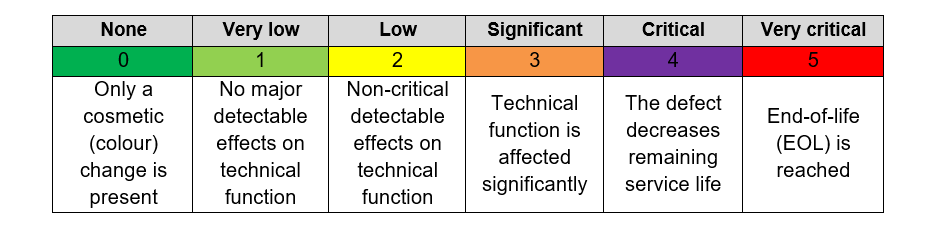
Table 2 - Condition severity classification [14]
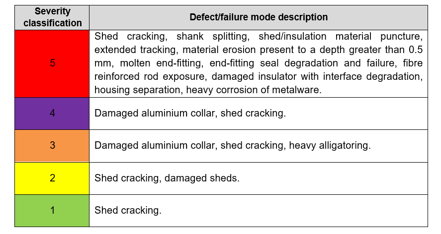
Table 3 - Categorisation of various defect/failure modes [14]
The disadvantage of the above categorisation practise is that certain defects, i.e. shed cracking, are present in more than one condition severity classification category – namely 1 to 5. This implies that the assessor must have specialist knowledge on what constitutes the differences in severity of said defects.
Experience gained through composite insulator tests at KIPTS has shown that without exception, once an insulator experienced material degradation that affected its profile, such an insulator would suffer accelerated material degradation leading to failure. A shed crack, puncture or tear results in a reduction of the insulator’s original and intended applied creepage distance. Hence, a reduction of creepage length reclassifies the insulator for a less polluted environment than originally intended, which in some cases might even be lower than what is necessary for the expected operating voltage level.
For this reason, the South African utility defined its own composite insulator severity classification for practical reasons [29]. To assess the condition and performance of an insulator in a specific environment, and to provide adequate solutions if problems persist, the various faults or defects that could occur are categorised according to one of three categories.
An insulator body that displays the defects or damage below is classified as Category 1 and should be immediately corrected or removed from the system and replaced with an insulator of suitable design. It is important to note that certain defects that would fall under Category 1 can only be discovered after dissecting the insulator.
Category 1 defects include:
- Grease leakage has occurred from the sealed end-fittings or shed interfaces with the rod.
- The insulating material is punctured.
- The fibre reinforced rod core is exposed.
- The insulator housing is split.
- The fibre reinforced rod is fractured (in some cases, not visible without detailed visual inspection and dissection).
- Burning has occurred on the insulator body (e.g. due to veld fires, power arcs, severe tracking, flashover and flash-under), this excludes burn/flash marks on end-fitting metalware which didn’t result in end-fitting seal damage.
- There is evidence of tracking.
- Material erosion is present to a depth greater than 0.5mm.
Defects that would require further investigation as to why they occurred are classified as Category 2.
Category 2 defects include:
- Flash marks on the insulator surface (especially close to end-fitting seal area).
- Evidence of damage due to handling.
- Moulding defects in the polymer material.
- Bird damage resulting in profile change.
- Potential defects identified by means of UV and IR scans.
Category 3 defects require that the condition and performance of the insulators be monitored annually while in service.
Category 3 defects are classified as follows:
- Chalking has occurred on the insulator surface.
- Discolouration of the insulating material has taken place due to the same mechanisms as chalking.
- There is crocodile skin effect/crazing on insulator surface.
- Fungal growth.

4.3. South African approach to in-service inspection methods and condition assessment
Insulator field failures can be partially mitigated by using experienced observers to inspect the overhead line insulators in detail by means of binoculars from ground level. Helicopter patrols can be used to view the insulators from a few metres with either binoculars or a video camera. However, apart from being very expensive, it is challenging to keep the helicopter adequately stable for a sufficiently long duration to detect subtle defects, such as missing split-pins or end-fitting sealing failure. A recent development is the implementation of RPAS systems that could potentially replace expensive helicopter patrols to an extent.
Visible insulator defects that must be identified during routine or emergency line inspections include:
- Evidence of flashover marks.
- Housing/shed damage.
- Housing erosion and metalware corrosion.
- Incorrect installation (i.e. insulator impaired movement, upside down corona rings and missing split pins).
- Trapped foreign objects such as wires hanging over insulators.
In addition to the above, UV and IR scans can be highly effective tools [30] to identify insulators which show signs of early or imminent internal electrical failure, which could also result in mechanical failure and conductor drop. This inspection can therefore serve as a proactive approach to determine the condition and life expectancy of in-service composite insulators (Figure 4).
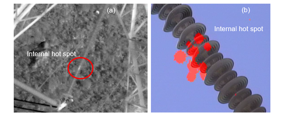
Figure 4 - IR (a) and UV scan (b) showing internal hotspots
Photos taken by E. Scholtz, Western Cape South Africa, 2019 (a) and 2025 (b)
Analysis of 221 Southern African Distribution lines inspected (ranging between 33 kV and 132 kV) over a period of 16 years has shown the prevalence of faults/defects on composite long rod and post type insulators in Table 4 [31].
Fault/Defect | Percentage of all defects | |
Long-rod insulators | Post-type insulators | |
Flashovers | 65% | 31% |
Housing/Shed damage | 20% | 62% |
Corrosion and housing erosion | 7% | 3% |
Incorrect installation | 6% | 4% |
Trapped foreign objects | 2% | 0% |
It is evident that flashover and housing/shed damage are the leading defects identified for both long-rod and post-type composite insulators.
The above practice may still result in field failures, as it is challenging to visually identify composite insulators that suffer from internal degradation, which is in the initial stages of development.
Condition analysis of in-service insulators and from retroactive inspection of field failures is based on the following steps [14], [32]:
- Comprehensive visual inspection.
- Review of the SPS if available, for the insulator service area.
- Localised Equivalent Salt Deposit Density (LESDD) measurements.
- Hydrophobicity assessment.
- Insulator profile assessment.
- Sample dissection.
- Material analysis.
- Data analysis and recommendations.
South African sub-transmission maintenance practices include the computation of a Health Index for substation electrical components [33], [34] and [35] which assign a condition rating to assets and serves to develop end-of-life criteria for the various asset types, which include insulators.
For insulators, the condition assessment and rating process includes:
- Visual inspections, which includes checking pollution build up, signs of tracking and erosion and bird droppings on insulator surface.
- Detailed reviews of maintenance records.
- Diagnostic test reports extracted from asset management system databases.
South African experience gained through research performed at a number of natural insulator ageing testing stations, and from insulator field failure investigations, has shown that the accuracy of any condition assessment process is highly dependent on the assessor’s skill and knowledge, available assessment equipment and that several details to be examined are in many cases impossible to determine from the ground level.
Furthermore, in cases where site pollution severity is the suspected contributor to poor insulator performance, field personnel use the following guidelines to diagnose insulator pollution related problems [36]:
- Line insulator flashovers that cannot be attributed to other causes such as lightning and fires.
- Insulator flashover history.
- Documented insulator flashover history during periods of rain, fog, mist or high humidity.
- Time of day that flashovers occur, i.e. the early morning is a good indication of pollution related problems [6].
4.4. Composite insulator condition assessment after removal from service
CIGRE guide TB 481 [14] presents commonly applied test philosophies for the assessment of in-service or failed composite insulators in the laboratory after their removal from service. The condition and ageing mode play a major role in the final determination of residual service-life for removed in-service composite insulators. Based on these recommendations, the South Africa utility perform insulator condition assessment by means of:
- Visual inspections
- LESDD measurements
- Hydrophobicity assessment
- Insulator profile assessment
- Sample dissection
- Material analysis
4.4.1. Visual inspections
Visual inspections start by identifying the insulator specimen’s features, such as:
- Manufacturer
- Production date
- Design generation (vintage)
- Materials used: housing (i.e. silicone rubber or EPDM), FRP rod and end fittings
- Installation data: name of distribution/transmission line installed, site pollution severity, in-service voltage, string configuration, number of years in service and failure history on similar units
Various forms of visible material damage to the insulators, especially room temperature vulcanised (RTV) silicone rubber (SR), may occur due to environmental and climatic conditions that increase electrical stresses on the insulation. A visual inspection documents and photographs all visible material degradation present on the housing material, as well as the interface between sheath and core.
Detailed photos are taken of the damaged areas and are then included in a structured assessment.
Four distinctive composite insulator damage visual identification categories are available [14]:
- Housing (e.g. shed cracking, shank splitting, shed puncture, shank tracking, bulk erosion, alligatoring, material loss).
- Rod (e.g. transportation/rough handling, thermal degradation, torsional damage, housing separation).
- End-fittings (seals and interface degradation, molten end-fittings after power arc, corrosion, moisture ingress).
- Hardware (e.g. aluminium collar, corona rings).
4.4.2. LESDD measurement
LESDD measurements are performed with a calibrated conductivity meter and special tool (see Figure 5) to obtain an estimate of the pollution level present on the surface of the insulator material. The LESDD measurement however only gives an indication of the pollution present on the surface of the insulator material, at the time the measurement was taken, and not of the site’s pollution severity levels. The LESDD test is performed in accordance with [37].
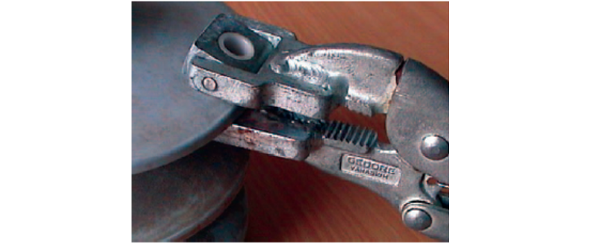
Figure 5 - LESDD sampling tool [37]
The LESDD is calculated using the same equations as those for the equivalent salt deposit density (ESDD), with the only differences being the surface area tested and the volume of distilled water used. However, care must be exercised in the interpretation of the results. It must be appreciated that the ESDD values relate to the contaminant averaged over the entire surface of the insulator, and not a single small area as per LESDD measurement [6].
In addition to the LESDD measurement, it is advantageous if the area specific ESDD, Non-Soluble Deposit Density (NSDD) and surface conductivity measurements are available to determine the pollution stress for the applicable service environment.
4.4.3. Hydrophobicity assessment
Examination of the hydrophobicity of composite insulators is an important part of the inspection process. A severe loss of hydrophobicity means that the insulation material is no longer performing as expected, especially from a pollution performance perspective.
The level of hydrophobicity may, however, change with time owing to, for example, environmental effects, partial discharge activity or corona. The water repellency can be defined in terms of the contact angle made between a water droplet and the surface. Such an angle, however, is difficult to measure in the field and a simplified method of classifying hydrophobicity was proposed by STRI and subsequently included in IEC/TS 62073 [38], “Guidance on the Measurement of Hydrophobicity of Insulator Surfaces”.
The assessment technique involves comparison of the appearance of the wetted insulator surface with that of a set of seven sample surfaces ranging from completely hydrophobic (HC 1) to completely hydrophilic (HC 7) [38], [39]. Examples of the different classes (1 to 6) are illustrated for reference in Table 5.
Hydrophobicity class (HC) | Description | Example |
1 (Hydrophobic) | Only discrete droplets are formed which are essentially circular in appearance when viewed from directly above. |
|
2 | Only discrete droplets are formed over a major part of the surface with droplets deviating from a mainly circular shape in appearance when viewed from directly above. |
|
3 | Only discrete droplets are formed. A major part of the surface is covered by droplets with an irregular shape. |
|
4 | Both discrete droplets and wetted traces from the water channels or water film are observed. Less than 10% of the observed area is covered by water channels or film. |
|
5 | Both discrete droplets and wetted traces from the water channels or water film are observed. More than 10% but less than 90 % of the observed area is covered by water channels or film. |
|
6 (Hydrophilic) | More than 90% but less than 100% of the observed area is covered by water channels or film (i.e. small non-wetted areas, spots or traces are still observed). |
|
7 Fully hydrophilic | Continuous water film is formed over the whole surface area. |
|


The hydrophobicity of insulator surfaces, particularly those of silicone rubber material, plays an important role in limiting the flow of leakage current and preventing pollution flashover [6]. Hydrophobicity in silicones results from the weak electrostatic bonds between the silicon and oxygen molecules, contributing to a low value of surface free energy determining the strength of adhesion between the surface and water. The surface resistance (electrical) of hydrophobic insulators is much higher than for hydrophilic insulator surfaces, as these surfaces tend to create islands of unconnected condensation and contamination (refer to HC 1 in Table 5). Hydrophilic surfaces, typically glass, porcelain and damaged hydrophobic surfaces, allow the condensate and contaminate to form a continuous layer on the insulator surface, resulting in high surface conductivity and resultant leakage current flow (refer to HC 6 in Table 5).
4.4.4. Insulator profile assessment
Insulator profile assessment determines whether the insulator was dimensioned in accordance with applicable international standards for area-specific site pollution severity and application [6]. The insulator’s dimensions are measured after the visual observations and LESDD and hydrophobicity tests are completed. This is to prevent disturbing any pollution and/or damage that might be found on the insulator.
A list of the key parameters that are measured can be found in Table 6.
Parameter | Value/Description |
Substation/Line |
|
Bay/Tower number |
|
Equipment/Insulator type |
|
Coating/Shed extender manufacturer |
|
Coating/Shed extender product code |
|
Alternating shed profile |
|
Shed design (under-ribbed/plain) |
|
Core diameter (mm) |
|
Large shed circumference (mm) |
|
Small shed circumference (mm) |
|
Shed projection (P), large (mm) |
|
Large shed spacing (S) (mm) |
|
Shed spacing/projection ratio |
|
Minimum distance between sheds (mm) |
|
No. of sheds, large |
|
No. of sheds, small |
|
Creepage from top to first shed (mm) |
|
Creepage per shed/shed pairs (mm) |
|
Creepage from bottom to last shed (mm) |
|
No. of shed extenders |
|
Diameter of shed extenders |
|
Creepage of shed extenders |
|
Total creepage distance (mm) |
|
System nominal voltage (kV) |
|
System maximum voltage (Um) in kV |
|
Specific creepage (mm/kV Um) |
|
Length of insulator (L) in mm |
|
Arcing distance (La) in mm |
|
4.4.5. Sample dissection
This step focusses on the dissection of insulator samples to determine or perform the following:
- Condition of the rod-to-sheath bonding, which is the adhesion between the glass fibre rod/core and the polymeric housing.
- Signs of moisture ingress through polymeric housing.
- End fitting seal condition and subsequent signs of moisture ingress.
- Examination of glass fibre rod condition.
- Detect the presence of structural changes to the chemical bonds of the insulation material that can lead to embrittlement.
4.4.6. Material analysis
A sample of the material may be sent for analysis to obtain a material fingerprint. Material analysis is used to determine the material condition for future reference in relation to the natural ageing process. The material analysis is performed in accordance with procedures pertaining to the accelerated laboratory ageing of insulators and fingerprinting of composite insulator materials [40], [41], [42].
The following fingerprinting test methods are recommended for removed field-aged composite insulators [41]:
- Hydrophobicity by static contact angle measurement.
- Surface compositional analysis by Fourier Transform Infrared (FTIR) spectroscopy measurement.
- Filler compositional analysis by Thermogravimetric Analysis (TGA) measurement.
- Compressive modulus analysis by Dynamic Mechanical Analysis (DMA) measurement.
- Microscopy of pollutants by Light Microscope (LM) and Energy Dispersive X-ray (EDAX) spectroscopy.
- Microscopy of surface with Scanning Electron Microscope (SEM) and EDAX after cleaning.
- Surface roughness by Atomic Force Microscopy (AFM).
5. Conclusions
The long-term performance of a composite insulator is affected by multiple factors, such as electrical stress, pollution levels and material ageing, which can result in a practical expected lifespan that ranges between 15 to 25 years. Therefore, composite insulator condition and end-of-life assessment is a complex task and cannot solely be achieved by external observations of an insulator sample, as some failure modes in various stages of progression is not apparent on the outside of the insulator.
South African experience gained through composite insulator research at KIPTS has shown that, without exception, once an insulator experienced material degradation that affected its profile, such an insulator would suffer an accelerated degradation, leading to failure. This correlates well with international surveys conducted over the years, which indicated that shed damage leading to decreased creepage distance and heightened risk of pollution flashover was the main reason to retire composite insulators.
Utilities are faced with the challenge of finding a proactive and objective approach to determine the condition and life expectancy of in-service composite insulators. Traditionally, insulator field failures are investigated in a retroactive manner, and only then can appropriate actions, such as replacement, be taken.
In this Part 1 of the two-part paper, composite insulator condition assessment and expected service life, including selection approaches have been reviewed, which Part 2 will utilise to define a holistic and a practical approach to composite insulator condition and end-of-life assessment according to the following conditions:
- Mechanical failure.
- Electrical failure.
- Loss in pollution performance requirements.
References
- SANS 60815-1:2009 (IEC/TS 60815-1:2008), “Selection and dimensioning of high-voltage insulators Part 1: Definitions, information and general principles”, Edition 1, 2008.
- SANS 60815-3:2009 (IEC/TS 60815-3:2008), “Selection and dimensioning of high-voltage insulators intended for use in polluted conditions Part 3: Polymer insulators for a.c. systems”, Edition 1, 2009.
- CIGRE Task Force 33.01.01, “TB 158: Polluted insulators: A review of current knowledge”, 2000.
- CIGRE WG C4.303, “TB 361: Outdoor insulation in polluted conditions: Guidelines for selection and dimensioning. Part 1: General principles and the AC case”, 2008.
- CIGRE WG B2.57, “TB 919: Experience with and Application Guide for Composite Line Insulators”, 2023.
- W. Vosloo, R. Macey and C. d. Tourreil, “The Practical Guide to Outdoor High Voltage Insulators”, Eskom Power Series,” Crown Publishers, 2006.
- L. Cheng, L. Wang and F. Zhang, “Aging characterization and lifespan prediction of silicone rubber material utilized for composite insulators in areas of atypical warmth and humidity”, IEEE Transactions on Dielectrics and Electrical Insulation, vol. 23, no. 6, pp. 3547-3555, 2016.
- K. Ning, J. Lu and Z. Jiang, “Aging characteristics and lifespan prediction for composite insulator silicone rubber in mountainous region environment”, Polymer Testing, no. 122, p. 10, 2023.
- EPRI and Southern Company 1001329, “Performance Prediction of Polymer Insulators for Distribution”, 2001.
- EPRI TR-111566, “Application Guide for Transmission Line Non-Ceramic Insulators”, 1998.
- I. Gutman, J. Lundegård and P. Sidenvall, “Condition assessment of line composite insulators: after-service test programs and their practical application”, Cigré Science & Engineering, no. 028, 2023.
- I. Gutman, “Service Experience with Composite Insulators”, Zimmar Holdings Ltd, 9 August 2024. [Online]. Available: https://www.inmr.com/service-experience-with-application-of-composite-insulators/. [Accessed 19 November 2024].
- L. Cheng, H. Mei, L. Wang, Z. Guan and F. Zhang, “Research on Aging Evaluation and Remaining Lifespan Prediction of Composite Insulators in High Temperature and Humidity Regions”, IEEE Transactions on Dielectrics and Electrical Insulation, vol. 23, no. 5, pp. 2850-2857, 2016.
- CIGRE WG B2.21, “TB 481: Guide for the assessment of composite insulators in the laboratory after their removal from service”, 2011.
- CIGRE SC 22 WG 22.03, “Guide for the identification of brittle fracture of composite Insulators FRP rod”, ELECTRA, vol. 143, 1992.
- IEC/TR 62662, “Guidance for production, testing and diagnostics of polymer insulators with respect to brittle fracture of core materials”, 2010.
- IEC 60383-1, “Insulators for overhead lines with a nominal voltage above 1000 V - Part 1: Ceramic or glass insulator units for a.c. systems - Definitions, test methods and acceptance criteria”, 2023.
- R. Davey and W. Vosloo, “Power Utility Perspective on Natural Ageing and Pollution Performance of Outdoor Insulators”, in IEEE Electrical Insulation Magazine 36(4), 2020, p. pp. 56-66.
- Eskom Research Report RES/RR/12/34595, “KIPTS research report 2012”, 2012.
- EPRI 1007769, “Polymer insulator survey”, 2003.
- EPRI 1007464, “Failure Analysis of Composite High Voltage Insulators”, 2002.
- EPRI 1024148, “Analysis of the EPRI Transmission Line Polymer Insulator and Fiberglass Component Failure Databases: 2012”, 2012
- I. Gutman, A. Deckwerth, K. Halsan, M. Leonhardsberger, P. Meyer, L. Diaz and M. Radosavljevic, “Application of Composite Insulators: Perceptions vs. Service Experience”, Proceedings of the INMR Congress, Berlin, 2022.
- Y. Xin and et al, “Aging characteristics and lifespan prediction of composite insulator SIR under multi-haze environment in coastal area”, Proceedings of the IEEE 5th International Conference on Dielectrics (ICD), pp. 1-4, Toulouse, 2024.
- S. Soto, D. Da Silva and R. Juliani, “Case histories of composite insulator performance in distinct service environments: Coastal, Mountain & Forest”, INMR, January 2024.
- CIGRE WG B2.03, “TB 333: Guide for the establishment of naturally polluted insulator testing stations”, 2007.
- Electric Power Research Institute, “EPRI Field Guide - Visual Inspection of Polymer Insulators", 2009.
- IEC 61109, “Composite insulators for a.c. overhead lines with nominal voltage greater than 1000V - Definitions, test methods and acceptance criteria”, First edition, 1992.
- Eskom Distribution guideline DIS SCABB2 revision B, "Inspection guid for high voltage insulators”, December 2004.
- J. Wang, I. Liang and Y. Gao, “Failure analysis of decay-like fracture of composite insulator”, IEEE Transactions on Dielectrics and Electrical Insulation, vol. 21, no. 6, pp. 2503-2511, 2014.
- R. E. Macey, “Eskom distribution overhead line inspections: Analysis of defects detected for period 1997 - 2013,” Mace Electrical Technologies, June 2013.
- EPRI Insulator Reference Book 3002010140 , Technical Update, December 2017.
- Eskom Standard 240-61182655, "Maintenance standard for substation electrical components rev 3”, 2020.
- Eskom Standard 240-86768812, "Maintenance standard for medium voltage overhead lines”, 2021.
- Technical Instruction 240-106383551, "Maintenance requirements for high voltage overhead networks”, 2016.
- Eskom Distribution Standard - Part 11, DST 34-504, "Standard for maintenance of insulators”, 2010.
- G. Besztercey, G.G. Karady, D.L. Ruff, “A novel method to measure the contamination level of insulators – spot contamination measurement”, Proceedings of the IEEE International symposium on electrical insulation, Arlington, June 1998.
- IEC/TS 62073:2016, “Guidance on the Measurement of Hydrophobicity of Insulator Surfaces,” Edition 2, 2016.
- CIGRE WG B2.69, “TB 837: Coating for improvement of electrical performance of outdoor insulators under pollution conditions”, June 2021.
- Eskom research report RES/RR/03/22239, “Procedure for accelerated laboratory ageing of insulators”.
- Eskom research report RES/RR/03/22240, “Procedure for fingerprinting composite insulator materials”.
- CIGRE WG D1.27, “TB 595: Finger printing of polymeric insulating materials for outdoor use”, October 2014.