Transformers and Reactors for Floating-Offshore- Substations. Technical requirements, solutions, experiences and outlook
Authors
Ewald TASCHLER, Martin STOESSL - Siemens-Energy, Austria
Joerg FINDEISEN - Siemens-Energy, Germany

Summary
The high demand for sustainable wind energy results in offshore wind farms at challenging locations like fare away from shore in deep water. For floating offshore wind farms expected in the next few years, floating offshore substations for different water depths will be required as well. New requirements and technology are necessary for these installations. The floating design of such substations requires that all components of the substation, in addition to being suitable for once-in-a-century waves and extreme weather events, also have the ability to withstand the long-term vibration loads caused by the sea over the entire service lifetime of the platform respectively a floating offshore substation.
The paper presents the analyses and evaluation of all new requirements, as well as the development of new technical solutions for mastering these requirements, particularly for the transformers and reactors of such floating offshore substations.
In preparation for the implementation of projects, extensive investigations and risk assessments with well-known quality tools like FMEA, cause and effect diagram, etc. were carried out for the components of the transformers and reactors of such new offshore floating substations.
The development work and results based on those assessments are presented in this paper and contains the following:
- The strength calculations and fatigue analyses carried out for the components of the transformers and reactors for the special floating requirements of such substations.
- The floating substation is exposed to changing angles of inclination during operation due to the sea state; the effects on the transformer components and the methods for managing these requirements are presented in the paper. Solutions for the oil conservator, the control of the level of the insulating liquid and the monitoring devices for the transformers and reactors are also presented.
- In order to also upgrade the components of the suppliers to meet the new requirements, extensive cooperation with them were required. Examples of this cooperation are presented in the paper.
- The paper also provides insights into an extensive test program for corrosion protection of offshore transformer components.
- A key message of the paper is that the requirements for floating applications need special measures on all components but can be managed with a high level of technical knowledge and sustainable solutions.
Keywords
Power transformer, Shunt reactor, Fatigue analysis, Floating-Substation, Structural analysis, Tap-changer1. Introduction
At present, a large number of floating wind turbines are already in use. Until now, these have mostly been situated near the coast and do not require an offshore substation. Individual projects form wind farms have floating substations, but these have so far only had low nominal outputs (appr. 25 ... 40 MW).
We have also supplied transformers for several floating platforms in the oil and gas industry. So far, these had outputs of up to 50 MW and rated voltages below 72.5 kV.
The corresponding development work is therefore required for the grid connection of future large floating offshore wind farms.
Together with our partners for the construction of the platform, we are currently investigating concepts for floating substations with capacities between 50 and 2000 MW. A variety of design types of the platform and the floater are considered.
The optimal design of the platform for the substation depends on the application, the nominal power and whether it is an AC substation or an AC/DC converter station. Sea conditions also have a significant influence on the design of the platform, depending on the installation area (Atlantic Ocean vs Mediterranean Sea), the water depth, the cable connection and the possible anchoring solutions for the substation.
Examples of such designs are shown in Figure 1.
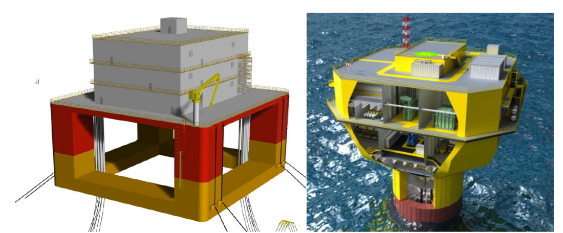
Figure 1 – Examples for different concepts for floating offshore substations
(Reproduced with permission from SAIPEM / Siemens-Energy)
The placement of the components on the platform, i.e. the distance from the centre of gravity in horizontal and vertical directions, has a significant influence on the balance of the platform and its actual movements and accelerations to which the individual components of the floating substation are exposed.
Therefore, precise position-dependent acceleration values must be specified for the required fatigue studies of the main components.
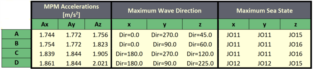
Table 1 - Extreme accelerations under cyclone with 100-year return period for different locations on the platform (A, B, C, D) 0
Components that are particularly sensitive to movement should therefore be accommodated close to the centre of gravity. For an optimal design of the substation that can withstand all environmental influences, close cooperation and coordination between the transformer designers and the platform designers is required. Since the transformers and reactors are the heaviest components of the substation, they are arranged as centrally as possible on the platform.
2. Mechanical strength
One of the biggest topics, when it comes to transformers for floating substations is the mechanical strength of the steel-parts, like tank and cover, radiator support structure, support structure of the conservator and many more. The size and weight of the most parts makes it impossible to put them on a shaker table to check their fatigue capabilities as we did for Windpower transformers. Our GIS/switching colleagues also verified their simulations, material models and analyses by tests. So, with the support from our experienced colleagues, we developed our fatigue assessment including FEM simulations to get the hotspots to verify.
2.1. Structural mechanics FEM simulation to identify stress hot spots
2.1.1 Geometry
To start with the simulation process, we need a 3-D Model of a tank from the tank design department. This 3-D model will be simplified and a Shell or a Solid-Shell model generated.
We also need an active part and its support structure (e.g. resin pots) for the simulation.
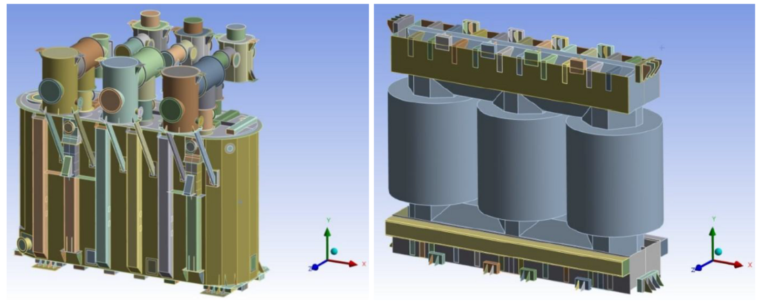
Figure 2 – Shell model from the transformer tank and the active part (partly shell)
2.1.2 Boundary conditions and loading
Six linear static analyses are to be performed, one with an acceleration load in each spatial positive and negative direction, and all six analyses with the inertia force of the oil on the tank according to the applied acceleration load.
Since a fulfilled static strength assessment under loading with self-weight and inner pressure is a precondition for the fatigue analysis and since regarding to [7] DNV-RP-C203, the mean stress won’t be considered in the fatigue investigation, as well as the hydrostatic pressure and the standard earth gravity won’t be applied.
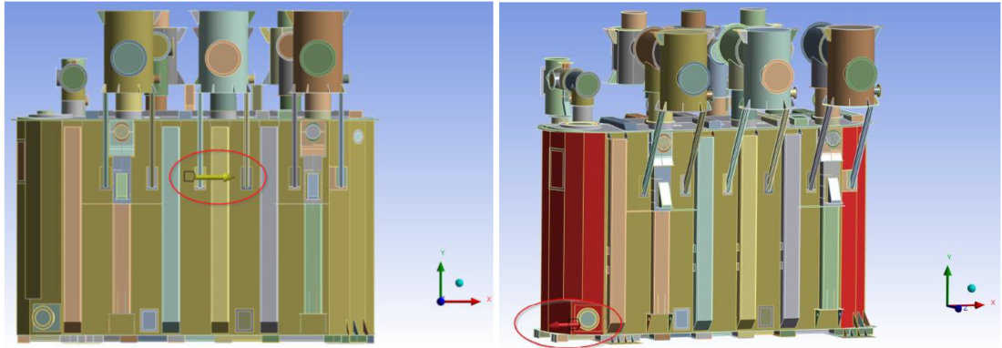
Figure 3 – Applied acceleration load in x-direction and inertia force of the oil applied to the transformer tank
Also, a fixed support for the tank bottom is applied and a frictional contact between active part and tank bottom.
2.1.3 Stress evaluation
In the simulation, the stresses are calculated with the maximal load in one direction. This means that the resulting stress will be the peak stress. For the evaluation stress the peak-to-peak stress is needed. The peak-to-peak stresses at critical locations required for the fatigue
assessment can be obtained directly from the peak stress results in Ansys:
(1)
2.2. Fatigue assessment approach
The calculated stresses can be compared with allowable stresses based on three different criteria:
- Criteria when a detailed fatigue analysis can be omitted
- Calculation of hot spot stress
- Simplified fatigue analysis (Weibull distribution)
2.2.1. Criteria when a detailed fatigue analysis can be omitted
According to DNV-RP-C203 detailed fatigue analysis can be omitted if the largest stress range is less than the fatigue limit at 107 cycles.
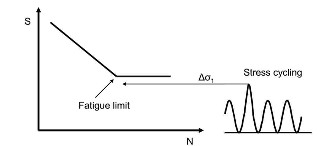
Figure 4 – Stress cycling without further fatigue assessment
Design fatigue factors (DFF) are to be applied to reduce the probability of fatigue failures. The calculated fatigue lifetime shall be longer than the design fatigue lifetime multiplied by the DFF. According to [1] DNV-OS-C101 the range of this factor is between 1 and 3. For components inside the tank or components containing oil, the highest value 3 shall be applied. For all other components the factor of 2 shall be used, as they are accessible for inspection and repair can be done under dry and clean conditions.
| S-N curve | DFF | DFF-0,33 | Δσallow_D (MPa) | Δσallow_B2 (MPa) |
|---|---|---|---|---|
| Components submerged by oil | 3 | 0,7 | 37 | 65 |
| Components accessible for inspection | 2 | 0,8 | 42 | 74 |
2.2.2. Calculation of hot spot stresses
Calculation of the hot spot stress shall be performed in accordance to [7] DNV-RP-C203 or [2] IIW Fatigue Recommendations with methodology A or B. For welded areas S-N curve type D and for not welded areas the S-N curve type B2 shall be used.
| S-N curve | D (MPa) | B2 (MPa) |
|---|---|---|
| FAtigue limit at 107 cycles | 52,63 | 93,59 |
| Probability of survival | 97,7% | |
2.2.3. Simplified fatigue analysis (Weibull distribution)
The calculated results from hot spot stress calculation shall be used for the simplified fatigue analysis (Weibull distribution).
The long-term damage accumulation shell be calculated for all wave directions separately as if they were acting for 20 years (transformer/reactor lifetime assumption). The assumed Weibull shape parameter is 1.1. Generally, DFF shall be taken from Table 2.
The long-term stress range distribution is permitted to represent by means of the two-parameter Weibull distribution where the Weibull scale parameter q is defined from the largest stress range level Δσ0 out of n0 cycles as:
(2)
where h is the Weibull shape parameter. The scale and shape parameters q and h, respectively, determine the probability of exceedance of a prescribed stress range Δσ:
(3)
Using this, it is possible to calculate the fatigue damage of a detail conservatively using a one-slope S-N curve using the following formulation:
(4)
| Td | s | Design life in seconds |
| v0 | 1/s | Average zero up-crossing frequency |
| ā | - | Intercept of the design S-N curve |
| q | - | Weibull stress range scale distribution parameter |
| m | - | Negative inverse slope of the S-N curve |
| h | - | Weibull stress range shape distribution parameter |
| T | - | Gamma function |
| - | Utilization factor |
The utilization factor is a function of the selected Design Fatigue Factor in accordance with [7] DNV-RP-C203, “Utilization factors η as function of design life and design fatigue factor’’ as shown in the table below.
| DFF | Design life in years | ||||||
|---|---|---|---|---|---|---|---|
| 5 | 10 | 15 | 20 | 25 | 30 | 50 | |
| 1 | 4 | 2 | 1,33 | 1 | 0,8 | 0,67 | 0,4 |
| 2 | 2 | 1 | 0,67 | 0,5 | 0,4 | 0,33 | 0,2 |
| 3 | 1,33 | 0,67 | 0,44 | 0,33 | 0,27 | 0,22 | 0,13 |
| 5 | 0,8 | 0,4 | 0,27 | 0,2 | 0,16 | 0,13 | 0,08 |
| 10 | 0,4 | 0,2 | 0,13 | 0,1 | 0,08 | 0,07 | 0,04 |
The damage calculation has been automated by a fatigue tool.
2.2.4. Example for the fatigue analysis on the cover
Fatigue assessment with S-N curve D because the highest stress is in a welded region.
Figure 5 shows, the hot spot is fatigue resistant.
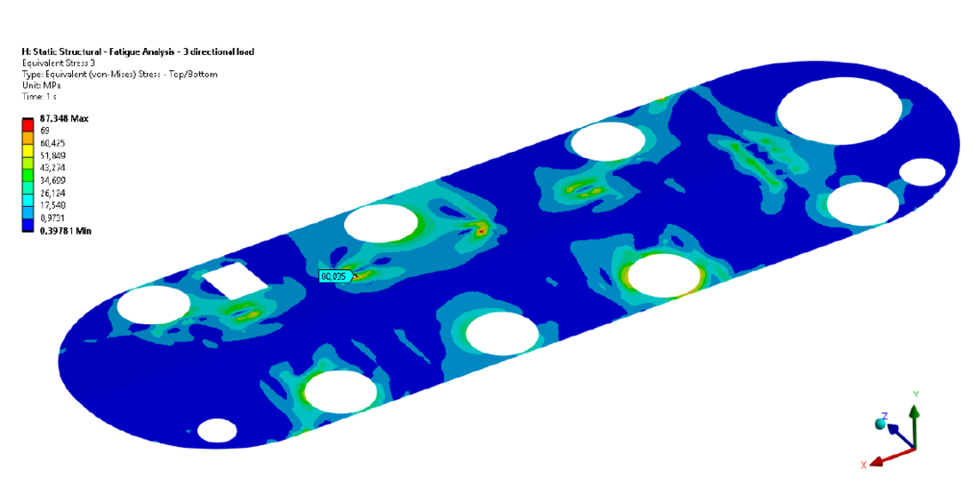
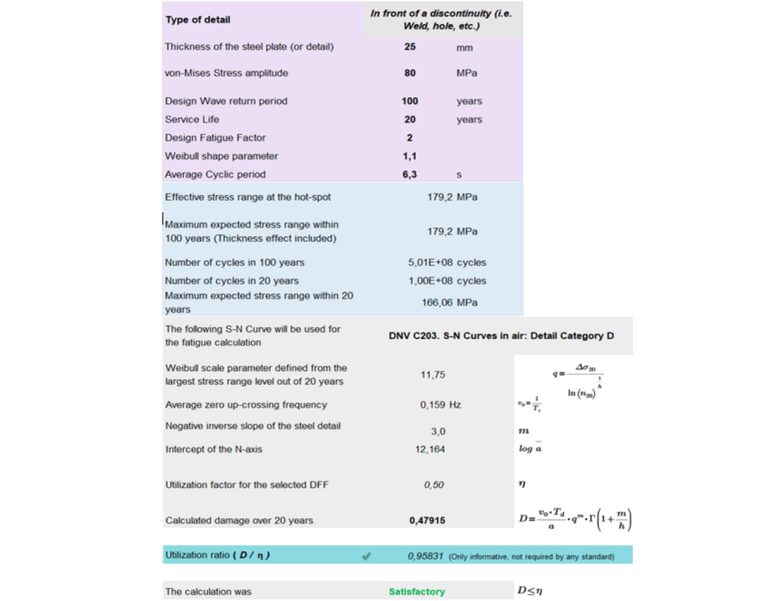
Figure 6 – Fatigue assessment – Tank cover
3. Active part
The active part is the heaviest component of a transformer. Since it is held together largely by friction, special measures are required to ensure its proper function.
To keep the stacks and the single sheets of the core in place, we use the option to bolt the core and paint the yokes. The limbs are also painted and bandaged, especially the return limb. Those measures are common practice for high transportation and seismic loads.
3.1. Fixation of the active part inside of the transformer tank
Due to the state of the sea, the occurring angles of inclination and the high mass of the active part, it is of great importance to fix the active part securely inside of the tank.
Various processes were investigated and fixation by using pots filled with cast resin was selected as the best solution (see figure 7).
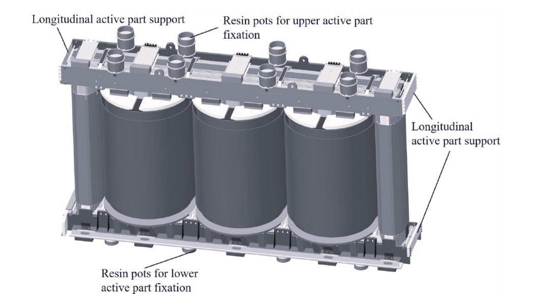
Figure 7 – Active part for floating applications
The active part is connected to the bottom of the tank and the cover of the transformer by these pots filled with cast resin. The fixation with cast resin is carried out during the assembly of the transformer. Once the resin is cured, there is no movement between the vessel and the active part possible and a secure fixation for inclinations and vibrations is guaranteed.

4. Investigations of important components
4.1. Tap-Changer
In accordance with our specifications, our partner and main supplier for tap changers carried out extensive investigations to upgrade the tap changers for floating conditions.
Special investigations for the tap-changer were required, as the mounting of the tap changer head on the cover of the tank and the resulting lever arm, due to the tap changer’s considerable length, result in a high load on the structure. For this purpose, the tap changer manufacturer conducted extensive simulations.
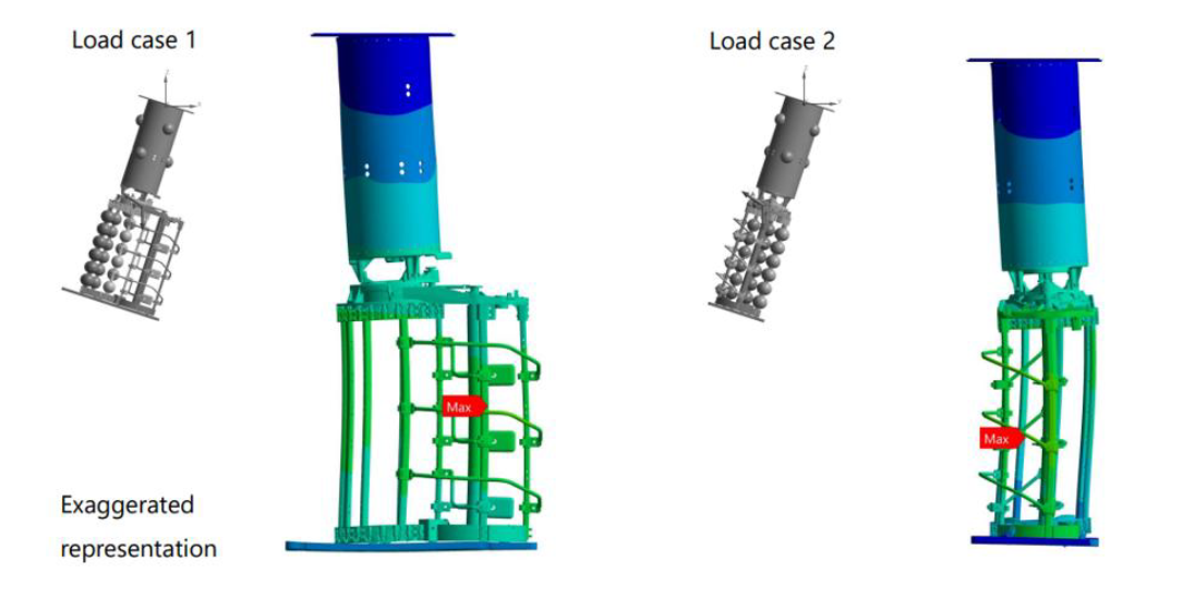
Figure 8 – Stress simulation for fatigue analysis
(Reproduced with permission from Maschinenfabrik Reinhausen)
Furthermore, the changeover between different switching stages is carried out by a rotary movement of the inner switching contact. It has been proven, that the gearshift process runs without restrictions even at the angle of inclination. For this purpose, practical switching tests were also carried out and the shifting capability at inclination was proven (Figure 5). These tests were conducted up to an angle of 20°. All tests passed, but according to the current status 15° is permitted for use.
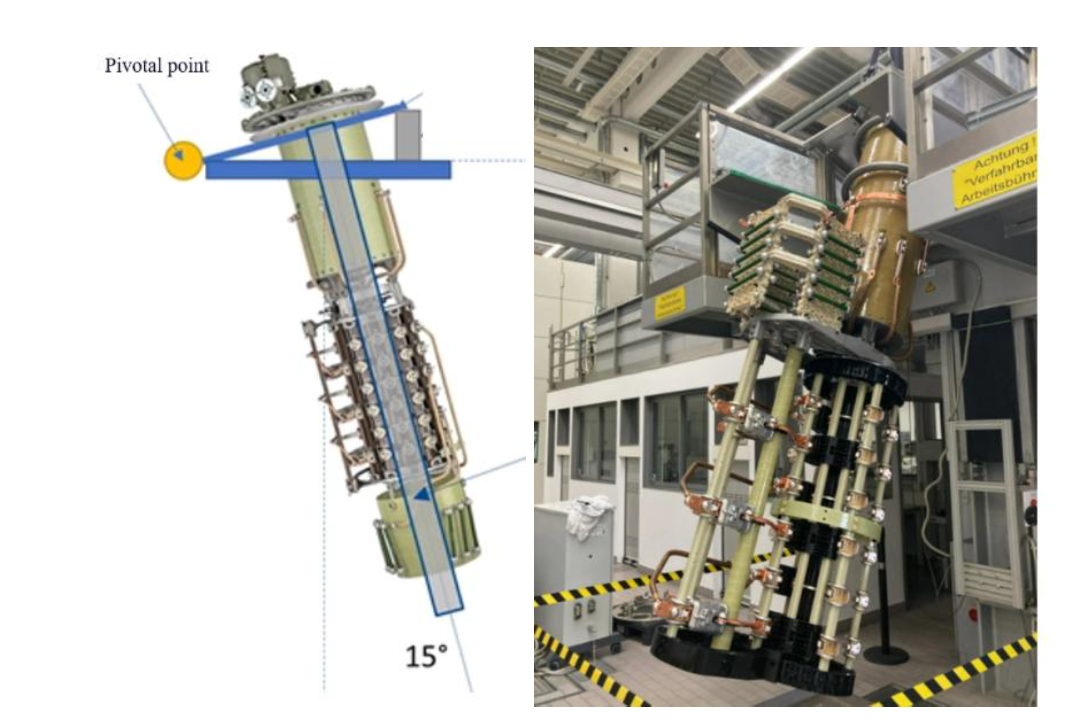
Figure 9 – Inclination test for tap-changer
(Reproduced with permission from Maschinenfabrik Reinhausen)
4.1.1. Measures for installing the tap-changer in the transformer
Further investigations have shown that in floating applications, support of the leads at the tap changer contacts results in high forces on the selector of the tap changer, when the inclination changes. Therefore, the distance between the consoles of the leads and the contact on the tap changer must be reduced (see Figure 10, on the left side).
Together with the manufacturer of the tap changer, variants were developed for the additional fixation of the tap changer on the active part or tank of the transformer (see Figure 10, on the right side).
The variant used depends on the type of tap changer and the height of the active part.
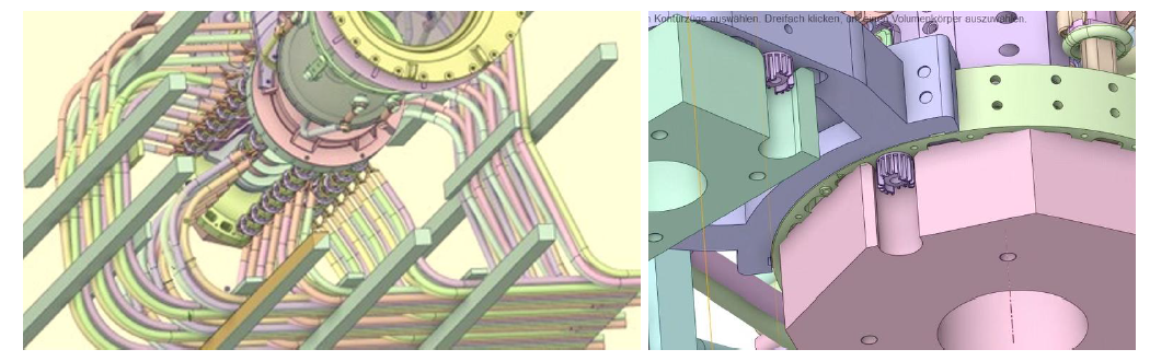
Figure 10 – Fixation of the leads to the tap changer contact (left)-Additional fixation on the bottom of the switch (right)
(Reproduced with permission from Maschinenfabrik Reinhausen /Siemens-Energy)
4.2. Conservator for insulation fluid
The angles of inclination and acceleration that occur in a floating application have a particularly critical effect in assemblies that are only partially filled with a liquid. This generates sloshing effects which result in high loads on the structure. In the case of transformers and reactors, this applies in particular to the expansion vessel or conservator for the insulating fluid.
The base for our considerations regarding the design of the conservator were previous investigations on the behavior of a conservator during load changes under inclination (see Figure 11).
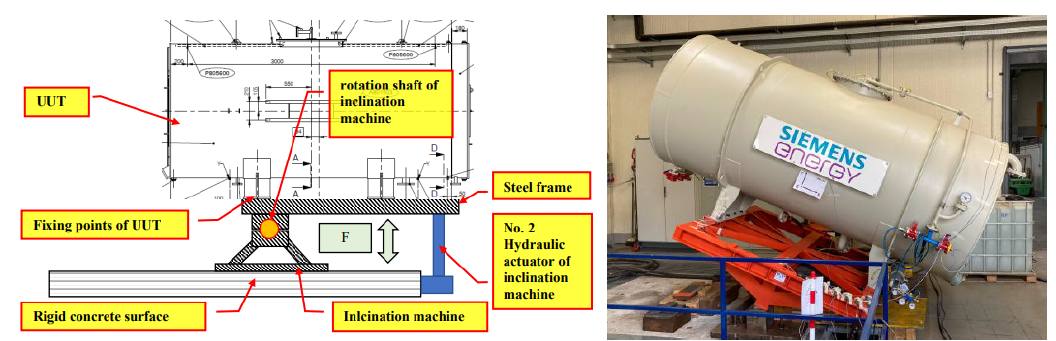
Figure 11 – Inclination test for conservator
(Reproduced with permission from Siemens-Energy)
To prevent damage caused by sloshing of the insulating liquid, protection walls (baffle plates) are installed in the conservator.
We have been using this technology for offshore transformers for several years in order to meet the stresses during transport to the installation site.
For use in floating-applications, the baffle plates were reinforced again. To prevent rotational sloshing, sloshing limiters are also attached to the jacket of the cylindrical vessel (see Figure 12).
In the meantime, several transformers for floating applications, mainly for floating gas production platforms, have been delivered using this reinforced new solution.
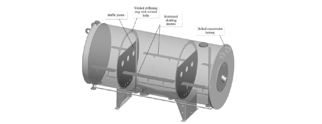
Figure 12 – Conservator for floating design
(Reproduced with permission from Siemens-Energy)
4.3. Oil Level Indicator in the conservator
In order to meet the special requirements of floating applications, several variants were examined for their suitability. In the following, some selected variants are evaluated.
4.3.1. Axial Oil Level Indicators (Classic Solution)
The floater is located below the rubber bag and has an axial movement (see Figure 15).
Due to the inclinations and the resulting oil movement, the resulting lateral forces stress the floater and can cause damage or deformation. The use for floating applications is not recommended.
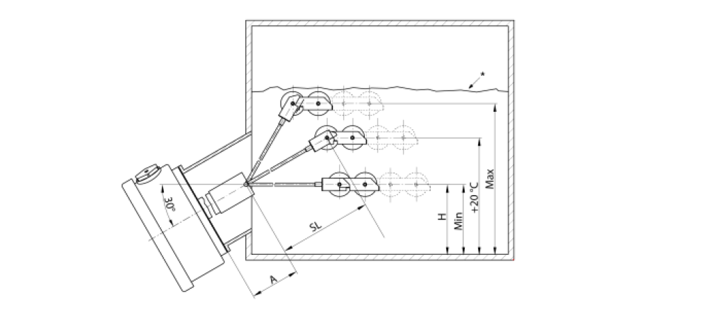
Figure 13 – Classic axial oil level indicator
4.3.2. Non-contact measuring systems (distance measurement systems)
Distance measurement systems are used to detect the position of objects. This measuring principle can be used to record the oil level or, when using a rubber bag, to measure the bottom of the rubber bag.
This requires measurement through an opening in the rubber bag.
The rubber bag has a flange for fastening and an opening for inflation after installation. The hole in the flange and the associated pipe section must be adjusted so that the sensor can be inserted through the flange into the pipe.
In this example, the sensor is mounted by an inserted T-piece in the pipeline above the opening of the flange. A UV sensor has proven to be well suited for this purpose. This variant was tested in a trial and found to be the most suitable (see figure 14).
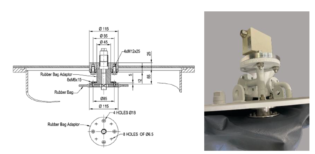
Figure 14 – Flange and pipe design with passage for UV sensor for level monitoring when using a rubber bag
(Reproduced with permission from COMEM /Siemens-Energy)
4.4. Buchholz relays
The Buchholz relay is the most important protective device for monitoring oil-filled transformers. Due to the difficult repair conditions for transformers and other components of the substation at sea, monitoring that is fully functional even under the dynamic loads at sea is of great importance.
To avoid false tripping, each contact system is designed to be insensitive to mechanical shocks that can affect the Buchholz relay from all directions.
The fission gases produced in the event of a fault migrate upwards through the fluid and collect in the upper area of the Buchholz relay, where they displace the insulating fluid. As the fluid level drops, the upper float sinks. After a certain movement of the float, which depends on the gas volume in the Buchholz relay, a switching contact is activated, and a warning is triggered. The influence of a transformer tilt on the triggering of the switching contact was investigated, i.e. whether the switching contact is actuated too early or too late (see Figure 10).
An experiment was conducted to determine the gas volume at which the triggering of the warning contact is affected at different tilt angles.
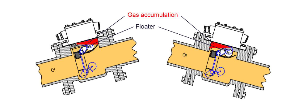
Figure 15 – Possible displacement of the gas accumulation in the Buchholz Relay when the transformer is tilted
(Reproduced with permission from Siemens-Energy)
Furthermore, the functionality of the Buchholz relay was tested at different inclination angles (see Figure 16).
Our partner and supplier of Buchholz relays has carried out and documented further tests, including vibration tests (see Figure 17).
The requirements of [10] IEC 60076-22-1:2019, sub-clause 7.1.4.3 “Vibration withstand test” were fulfilled. The test has passed successfully. No false tripping of the switches was recorded during the tests.
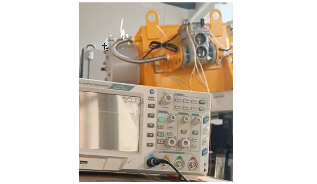
Figure 16 – Function test of the Buchholz relay at inclination
(Reproduced with permission from Siemens-Energy)
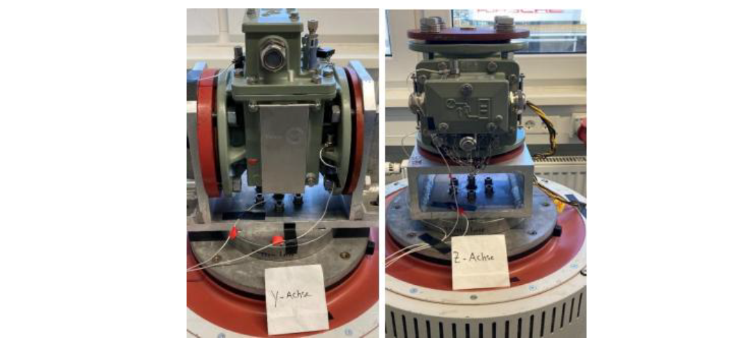
Figure 17 – Vibration test on the vibration plate (shaker)
(Reproduced with permission from Maschinenfabrik Reinhausen / MESKO)
5. Selection and testing of components for floating substations from a corrosion point of view
With a floating offshore substation, repair work and replacement of components are much more difficult to carry out compared to permanently installed offshore platforms, as the sea state limits the use of hoists, cranes and tools. This reduces the time windows for maintenance work compared to conventional offshore platforms. Furthermore, additional safety measures for maintenance personnel are required in the event of swaying platforms.
This means that in floating offshore substations, even tougher selection procedures must be applied for the assemblies and components used.
For this purpose, we have conducted a comprehensive test program for a large number of components and are continually expanding it to include additional parts and components.
We conduct these tests together with a testing laboratory to increase the validity of the results and maintain a consistent basis for comparison across all components from different suppliers.
Most structural components, and especially accessories, consist of a multitude of individual parts. These parts can be made of different materials and manufactured using different manufacturing technologies. The interfaces between the individual parts made of different materials are very susceptible to corrosion (contact corrosion). For this reason, we test a large number of critical components (e.g. fans, radiators, valves, etc.) using a test procedure based on [3] International standard ISO 12944;1-9 “Paints and varnishes – Corrosion protection of steel structures by protective paint system”. Figure 15 shows a test cycle according to this standard. The total duration of the test was 25 cycles or 4200 hours
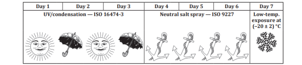
Figure 18 – Cyclic ageing test according to ISO 12944-9 [3]
We evaluate the suitability of these components for use in harsh environments on offshore platforms. Depending on the test results, measures were taken for further improvement of the relevant components and interfaces to prevent premature failure.
Examples of corrosion on transformer accessories after participation in the test program according to [3] International standard ISO 12944;1-9 “Paints and varnishes – Corrosion protection of steel structures by protective paint system” are shown in the figures 19 - 23.
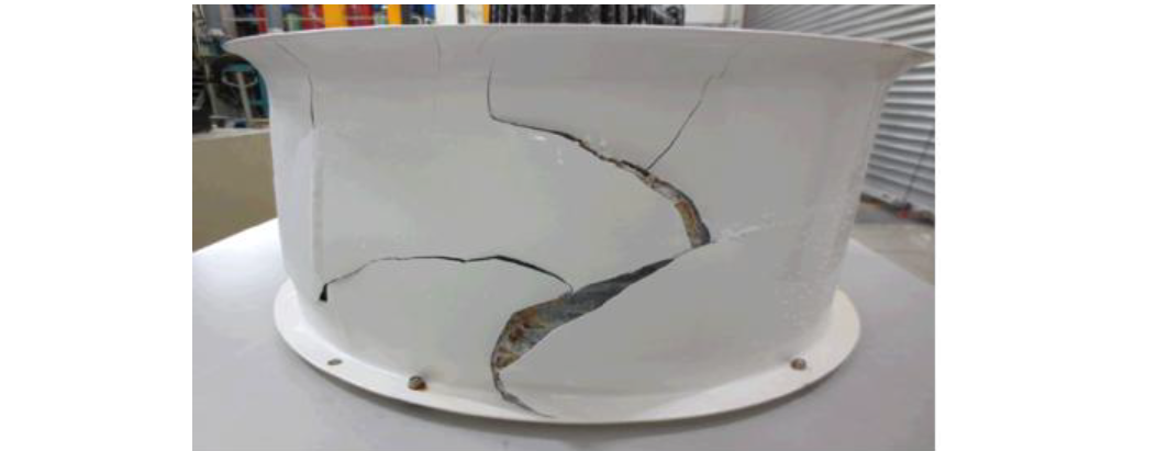
Figure 19 – Damage to the paint of a fan housing after the test
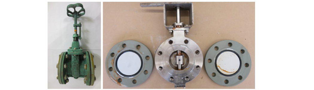
Figure 20 – Damage to a gate valve and butterfly valves after the test
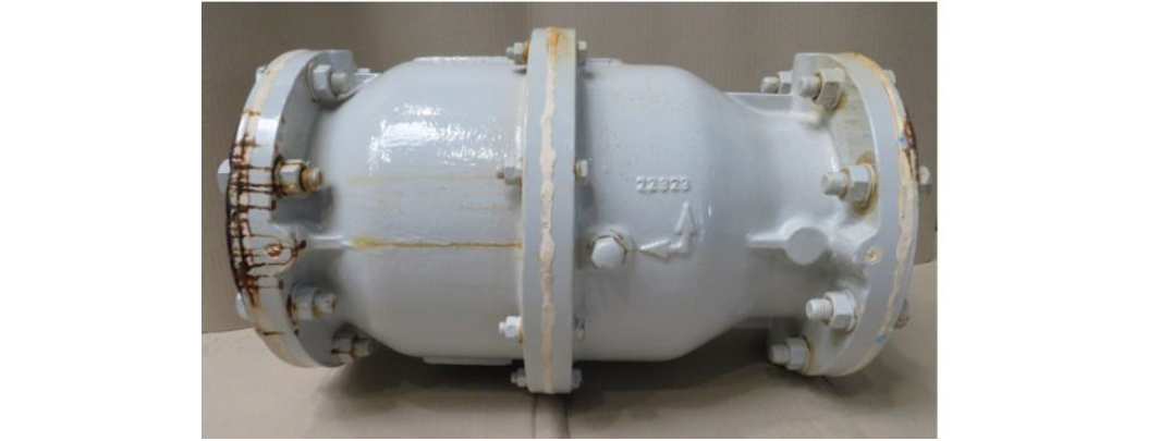
Figure 21 – Pump housing after the test
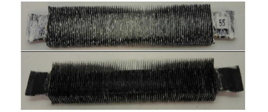
Figure 22 – Fins of an oil-air cooler after the test

Figure 23 – Damage to radiators after the corrosion test Left - Infiltration and flaking of the paint structure Center – Blistering due to underlaying rust Right – Damage to the edges
(Figure 19 - 23 Reproduced with permission from Siemens-Energy)
Based on the results of the corrosion and ageing tests, the components are usually further developed or improved in collaboration with the suppliers.
Only components that have been assessed as suitable for offshore use after appropriate improvements receive approval for use.
An important finding is that corrosion resistance is not only determined by the type of corrosion protection, but that the manufacturer's mastery of the production processes and corrosion protection procedures is crucial in order to meet the high offshore requirements.
6. Conclusion
The paper demonstrates that the requirements for floating offshore applications need special measures on the most critical components of a transformer or reactor but can be managed with a high level of technical knowledge and intensive simulations and tests. Sustainable solutions need an intensive collaboration between suppliers of the platform as well as suppliers of critical components and the transformer respectively reactor supplier. All these efforts and the gained knowledge allows us to design, manufacture and operate reliable floating offshore substations for the energy supply of the future.
References
- DNV-OS-C101 - Structural design of offshore units
- IIW Fatigue Recommendations IIW-1823-07/XIII-2151r4-07/XV-1254r4-07 Dec. 2008
- International standard ISO 12944;1-9 “Paints and varnishes – Corrosion protection of steel structures by protective paint system” (ISO Standard)
- International standard IEC 60076-14 “Power transformers – Part 14: Liquid-immersed power transformers using high-temperature insulation materials” (IEC Standard, Edition 1.0, September 2013)
- DNVGL-ST-0145, “Offshore substations”, 2020
- IEC 61892 Series, “Mobile and fixed offshore units – Electrical installations”
- DNV-RP-C203, “Fatigue design of offshore steel structures, Edition 2019-09
- IEC 60076-2, “Power transformers – Part 2: Temperature rise for liquid-immersed transformers”, Edition 3.0, February 2011
- CIGRE WG A2.107 Influence of harsh operation conditions present on offshore platforms to the design of power transformer and shunt reactors - Ref A2-111_2020
- IEC 60076-22-1:2019, sub-clause 7.1.4.3 “Vibration withstand tests”