A1 - Qualification of a HV-insulation system ACC. IEC 60034-18-42 for a hydro generator operating with inverter technology
Authors
Thomas HILDINGER - Voith Hydro, Germany
Christian STAUBACH - HS Hannover, Germany

Summary
Electric energy, simply called electricity, is the backbone of modern life and social wealth. Electricity is essential for modern life and has a huge impact on modern life, as it is used for many purposes and applications in our daily lives.
Hydropower is a form of renewable energy that uses the force of water to generate electricity. Hydropower plays an important role in the reliable electricity supply since more than 100 years and is a clean and renewable source of energy. It has many benefits for the environment, society, and economy. Hydropower is crucial in Austria and Australia, contributing significantly to its energy mix. Hydropower helps to achieve energy security, reduce reliance on fossil fuels, and meet sustainability goals by generating clean electricity. Additionally, it supports economic growth, job creation, and environmental conservation, reinforcing commitments to a greener energy future. Furthermore, hydropower plays a vital role in efforts to mitigate climate change.
In recent years, the development of power electronics, more specifically frequency converter technology, has made it possible to apply high-power variable speed motor generators, providing unique advantages for grid stabilization. The use of variable speed motor generators generally offers advantages that may justify the greater investment. These include, among other benefits:
- Power control when operating in pump mode (motor).
- Extended turbine operating range.
- Fast regulation.
- Dynamic support for the electrical network.
This paper presents details about a successful qualification of high voltage stress grading systems for stator and rotor insulation in accordance to IEC 60034-18-42 standard. The developed inverter pulse source allows not only to generate the required bipolar square-wave but also to perform further parameter investigations on the resulting thermal and electric stress in the insulation system due to variable setting of repetition frequency, peak voltage and impulse rise time.
In general, a stress grading system performing sufficient under power frequency at sinusoidal voltage may behave totally different under impulse voltages and makes comprehensive investigations especially on hot-spot temperatures reasonable.
With regards to the presented dielectric measurements, i.e., dissipation factor, it can be concluded that either the aging during the qualification is not significant or the dissipation factor is not appropriate to assess the condition of the aged bars.
Keywords
High-Voltage, Hydro-Generators, Motor-Generators, Frequency Converter, Inverter Operation, IEC 60034-18-421. Introduction - Electric energy
Electric energy, simply called electricity, is the backbone of modern life and social wealth. Electricity is essential for modern life and has a huge impact on modern life, as it is used for many purposes and applications in our daily lives. Some of the ways electricity affects modern life are [1,2, 3,4]:
- Electricity provides clean, safe, and reliable light around the clock, which enables us to see and work in the dark, and to enjoy various forms of entertainment, such as reading, watching TV, or playing video games.
- Electricity cools our homes on hot summer days and heats many of them in winter, which improves our comfort and health, and reduces the risk of heatstroke or hypothermia.
- Electricity breathes life into the digital world we tap into with our smartphones and computers, which allows us to communicate, access information, learn, work, shop, and socialize online.
- Electricity powers many appliances and devices that make our lives easier and more convenient, such as refrigerators, microwaves, washing machines, hair dryers, vacuum cleaners, and electric toothbrushes.
- Electricity enables medical devices and equipment that save lives and improve health, such as X-rays, MRI, pacemakers, ventilators, and defibrillators.
- Electricity drives many modes of transportation and communication that connect us with the world, such as electric trains, cars, buses, trams, subways, and telephones.
- Electricity supports industry and innovation that create wealth and jobs, such as steel fabrication, car assembly, milking cows, and electric vehicles.
2. Hydropower
Hydropower is a form of renewable energy that uses the force of water to generate electricity. Hydropower plays an important role in the reliable electricity supply since more than 100 years and is a clean and renewable source of energy. It has many benefits for the environment, society, and economy. Some of the benefits of hydropower are [5, 6, 7]:
- Clean and renewable: Hydropower does not emit greenhouse gases or pollutants, and it relies on the water cycle, which is driven by the sun, making it a renewable source of energy.
- Flexible and reliable: Hydropower can adjust to the demand for electricity quickly and efficiently, and it can provide backup power during outages or disruptions. Hydropower also complements other renewable energy sources, such as wind and solar, by providing storage and balancing services.
- Affordable and durable: Hydropower provides low-cost electricity and has a long lifespan compared to other sources of energy. Hydropower facilities can also use existing structures, such as dams, bridges, and tunnels, to reduce construction costs.
- Multipurpose and beneficial: Hydropower provides benefits beyond electricity generation, such as flood control, irrigation support, drinking water supply, recreational opportunities, job creation, and economic growth. Hydropower can also enhance food security, pollution control, and carbon reduction.
3. The Limberg Scheme
The Limberg pumped storage schemes are notable hydropower projects in Austria. Located in the province of Carinthia, these schemes consist of several interconnected power plants, including the Limberg I and Limberg II and the future Limberg III facilities. Limberg I, commissioned in 1972, and Limberg II, commissioned in 2013, together form a complex that leverages the elevation difference between two reservoirs. The Limberg pumped storage schemes contribute to Austria's energy grid stability, providing rapid response capabilities to fluctuations in demand. The Limberg pumped storage schemes also play a crucial role in supporting the integration of renewable energy sources, such as wind and solar, into Austria's power grid. The Limberg 1 pumped storage plant is part of the Kaprun Oberstufe complex and was equipped with 2 constant rotation units and with a total power of 110 MW. Figure 1 shows a view of the original configuration [8, 9]. As part of an extensive modernization, the original electrical machines were replaced by variable speed synchronous motor generators, connected to frequency converters in the CFSM topology, with the following characteristics, shown in Figures 2 and 3.
- Rated Power: 81.5 MVA / Rated Voltage: 6.4 kV / Rated Current: 7 352 A / Power Factor: 1.0
- Frequency: 26.7~50 Hz / Operating Speed: 400-750 rpm / Maximum Speed: 1200 rpm
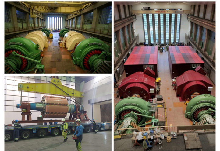
Figure 1 - Views of the original Limberg1 units (top left), of the rotor of the new variable speed units (bottom left)
and of the new variable speed units (right)
The new motor generators were commissioned in 2020 and are in full operation and have had their insulation system qualified according to IEC 60034-18-42.
4. The Snowy 2.0 Project
Providing up to 2,000 megawatts of on-demand energy (from standstill to 1000MW in 90 sec and in further 170 sec from 1000MW to 2000MW) for the national electricity grid Snowy 2.0 is a major pumped hydro expansion project in Australia. It involves constructing a new underground power station and storage facility to enhance the Snowy Mountains Hydroelectric Scheme's capabilities, providing increased energy storage and grid stability. Snowy 2.0 aims to support renewable energy by acting as a large-scale battery, storing excess energy during periods of low demand, and releasing it when demand is high. It's considered a crucial part of Australia's efforts to transition to a more sustainable and resilient energy system. The Snowy 2.0 project involves connecting the Tantangara Reservoir with the Talbingo Reservoir through underground tunnels and a new underground power station. This design allows for the generation of electricity by releasing water from the upper reservoir to the lower reservoir during peak demand, and then pumping it back up during periods of low demand using excess electricity from the grid. It's a complex engineering endeavour with the potential to contribute to grid reliability and the integration of renewable energy sources.
The Sonwy 2.0 Powerstation comprises 6 units with 3 of them being conventional fix-speed synchronous machines and the remaining 3 units being DFIM, with the main data according to the Table 1.
| Main Data | Variable Speed | Fixed Speed |
|---|---|---|
| Maximum Motor Power (shaft) | 362 MW | 362 MW |
| Maximum Generator Power (stator) | 396 MVA | 412.5 MVA |
| Speed Range | 455 - 533 rpm | 500 rpm |
| Power Factor at Stator / Transformer LV Terminals | 0.92 / 0.90 (lagging) | 0.90 / 0.90 (lagging) |
| Stator Voltage | 15.0 kV (+/-10%) | 15.0 kV (+/-10%) |
| Stator Voltage Extended Range | +14% / -16% | +14% / -16% |
| Stator Frequency | 50 Hz | 50 Hz |
| Rated Rotor Current (G-Mode) | 7 040 A (AC) | 2 299 A (DC) |
| Rated Rotor Voltage | 4.4 kV (AC) | 185 V (DC) |
| Rotor Frequency (continous operation) | 0.2 - 4.5 Hz | 0 (DC) |
4.1. Importance of Pumped Storage
Pumped storage plays a crucial role in energy systems by providing a means to store and manage electricity. It helps balance supply and demand, supports grid stability, and facilitates the integration of renewable energy sources like wind and solar, which can be intermittent. Additionally, pumped storage allows for the efficient use of excess electricity during periods of low demand, storing it for later use during peak demand, contributing to overall grid reliability and resilience. Pumped storage also offers benefits in terms of grid flexibility and frequency regulation. It provides a rapid response to fluctuations in electricity demand, helping to stabilize the grid by quickly adjusting the output. This capability is especially valuable as the share of variable renewable energy sources increases. Furthermore, pumped storage contributes to energy efficiency by capturing and reusing excess energy that would otherwise go unused, enhancing the overall performance and reliability of the electrical grid. Pumped storage facilitates energy arbitrage, allowing for the purchase of electricity during periods of low prices and its subsequent sale during peak demand when prices are higher. This economic aspect helps utilities optimize their resource utilization and can lead to cost savings for consumers. Additionally, pumped storage projects often have long operational lifespans, contributing to the longterm sustainability and reliability of energy infrastructure. The environmental impact of such systems is generally lower compared to certain other forms of energy storage, making pumped storage a valuable component in achieving a more sustainable and resilient energy future.
Pumped storage also supports grid resilience during emergencies or unforeseen events. Its ability to provide rapid response and stabilize the grid makes it an asset in mitigating the impact of sudden disruptions, ensuring a more robust and reliable power supply. Furthermore, pumped storage can enhance the integration of variable renewable energy sources by effectively smoothing out fluctuations in electricity generation, thus promoting a more balanced and stable grid that can accommodate a higher proportion of renewable energy. This adaptability is increasingly crucial as the world transitions to cleaner and more sustainable energy systems.
4.2. Adjustable Speed Technologies
In recent years, the development of power electronics, more specifically frequency converter technology, has made it possible to apply high-power variable speed motor generators, providing unique advantages for grid stabilization [10]. The use of variable speed motor generators generally offers advantages that may justify the greater investment. These include, among other benefits:
- Power control when operating in pump mode (motor).
- Extended turbine operating range.
- Fast regulation.
- Dynamic support for the electrical network.
In this way, a reversible plant equipped with variable rotation machines can react with maximum flexibility to equalize the volatile electrical energy generation from wind and solar farms. By introducing variable speed technology, the energy absorption in pump (motor) mode from the grid can be adjusted and also the transition between operating modes is significantly faster when compared to a classic reversible turbine-pump application. Currently, there are 2 basic concepts available on the market in terms of variable speed motor generators:
- Double-fed induction machines (DFIM) with inverter on the rotor side (AC excitation).
- Synchronous machine with full power inverter on the stator side (CFSM).
A basic principle for energy conversion in any type of hydrogenerator – whether fixed or variable speed – is that both the rotating magnetic field produced by the armature and the field produced by the rotor must always rotate at the same “electrical” speed. When the machine is operating under load, an angle is created between these two magnetic fields depending on the machine's torque. With the machine under static load, both fields must have the same frequency, otherwise it would not be possible to transmit a constant torque. With the introduction of the variable speed solution, the rotational speed of the magnetic field can be dissociated from its classical generating origin. One solution to this requires the installation of a frequency converter between the mains and stator winding, whilst an alternative solution requires a rotating magnetic field in relation to the rotor – which usually consists of a threephase rotor winding fed by a converter. frequency connected to the rotor. Figure 2 shows the basic topology of both solutions [10].
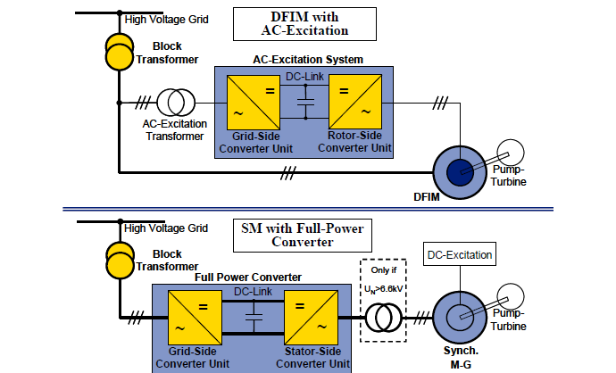
Figure 2 – Variable rotation machine topologies: DFIM at the top and CFSM at the bottom
4.3. Full power inverter synchronous machine (CFSM)
The armature system is disconnected from the grid and the electrical machine basically works as a synchronous generator with some adaptations, as described below. A full power inverter connected to the stator is used to “de-synchronize” the frequency, the rms value of voltage and current, as well as the phase sequence. The basic advantages of this concept result from the complete “desynchronization” of the network machine:
- Standard synchronous generator is used as an electrical machine, that is, the most tested, reliable, and efficient type of machine for large hydrogenerators.
- Maximum flexibility, with operating speed range limited only by the hydraulic machine.
- Truly agile starting and changing of operating modes of the unit since, thanks to the power converter, the machine can be accelerated from rest to operating speed with torque values close to the nominal torque and without the usual time delays for the unit synchronization.
- On the other hand, it is necessary to accept:
- High converter costs due to the connection with the stator (total machine power).
- Drops in efficiency in the unit due to losses in the converter.
- Provision of significant space for converter installation.
4.4. Double Feed Induction Machine (DFIM)
In this machine concept, the magnetization vector of the rotor field is dissociated from the rotor itself, and the result is that the magnetic field presents a relative movement around the rotor, which creates a relative rotational speed of the rotor in the direction of the field. of the stator. The mechanical speed of the rotor body itself is then the result of the rotational speed of the stator magnetic field plus that of the rotor magnetic field relative to the rotor body.
The stator is connected to the grid by a transformer, while the rotor is fed by slip rings, with another asymmetric three-phase AC system of variable amplitude and frequency produced by an AC excitation system. Thus, by adjusting the rotor frequency with the AC excitation system, the rotor speed (coupled to the turbine-pump) can be adapted to hydraulic needs. In other words, by controlling the frequency of the rotor currents, the rotational speed can be adjusted around the synchronous speed. Furthermore, by controlling the rotor current amplitude, the stator reactive power can also be controlled in a similar way to that of the classical synchronous machine. Additionally, it is also possible to supply reactive and capacitive (overexcited) power to the AC excitation system via the grid-side converter. In the sum of the powers of the excitation system and the stator, the specified power factor for the complete unit (machine and converter) is provided on the low voltage side of the machine transformer.
5. Qualification according to IEC 60034-18-42
The IEC Standard 60034-18-42 describes the qualification scope for partial discharge resistant electrical insulation systems (Type II) used in rotating electrical machines fed from voltage converters [11]. Especially for HV-insulations systems equipped with conductive armor tape (CAT) and non-linear stress grading tape (SGT) the performance of these components is quite different between sinusoidal excitation and converter operation [12, 13, 14]. Whereas the expected electrical lifetime of the main insulation under converter stresses can be estimated by means of mathematical equations based on the performance at power frequency this is not possible for the stress grading system due to its nature [11].
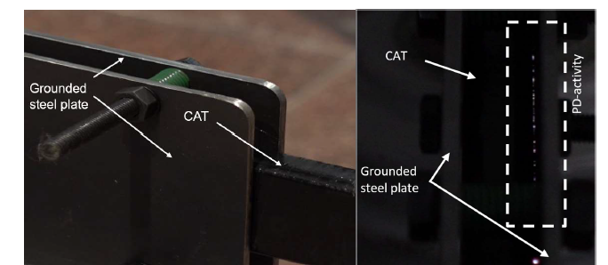
Figure 3 – PD-activity between CAT-surface and the grounded steel plates at a repetition frequency of 1.5 kHz
As an example, Figure 3 shows formation of PD-activity between a grounded steel plate as core simulation and the CAT-surface during inverter excitation with a repetition frequency of 1.5 kHz. In this particular case the electrical stress is simulated by a bipolar square-wave voltage with a peak-topeak voltage ?pk/pk≈ 4 kVpp.
At 50 Hz power frequency with comparable voltage magnitude no PD is present at all. The PD-activity is caused by the different field distribution at inverter excitation in combination with insufficient contacting. In a real machine this failure type will result in accelerated deterioration of the CAT and finally lead to severe slot discharge activity and reduced electric lifetime [15]. Therefore, the insulation system must be optimized for inverter operation to minimize the risk of such failure mechanism [16]. To verify the appropriate design the tailored insulation system is then qualified according to IEC 60034-18-42.
5.1. Qualification scope according to IEC 60034-18-42
The qualification scope is concentrated on the stress grading system, i.e., CAT and SGT. The expected converter stresses during operation of the real machine are transferred to testing parameter for the lab testing. In chapter 11.2 of the IEC 60034-18-42 some general statements are given. The pulses generated in the lab should have parameters, such as repetition frequency ?, peak voltage and impulse rise time ?r (unipolar or bipolar), comparable with operation. In case some of the relevant converter parameters are not know, the Standard gives recommendation, like for repetition frequency ? and impulse rise time ?r. The following Table 2 gives an overview about the relevant electrical parameters provided by the manufacturer for the converters. The first converter is used for a doubly fed induction machine (DFIM), the second one for a synchronous machine (CFSM) with full converter-technology.
| Parameter acc. IEC 60034-18-42 | DFIM | CFSM |
|---|---|---|
| Repetition frequency f | 0.9 kHz | 1.0 kHz |
| Voltage step level Ua | 4800 V | 3500 V |
| Voltage overshoot factor ub | 1.3 | 1.2 |
| Jump voltage Uj | 6.24 kV | 4.20 kV |
| Voltage rate dU/dt | ≈ 1.0 kV/us | ≈ 1.5 kV/us |
| Peak-to-peak impulse-voltage | 8.11 kV | 5.46 kV |
| Peak-to-peak voltage | 24.0 kV | 15.4 kV |
Chapter 13.4 defines the different parts of the qualification program. It includes a block of 100 h impulse testing, followed by a second block of 1000 h AC-testing with power frequency and a final block of 100 h impulse testing. The peak-to-peak impulse-voltage of the bipolar square-wave signal generated in the lab is calculated according to the following Equation (1).
(1)
The RMS-voltage ?RMS of the AC-testing is dependent on the peak-to-peak voltage ?pk/pk and is derived according to Equation (2).
(2)
In Table 3 the derived electrical parameters for the 3 aging cycles according to IEC 60034-18-42 are summarized.
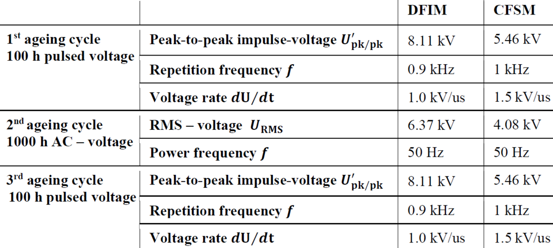
Table 3 – Derived test parameters for the qualification acc. IEC 60034-18-42
5.2. HV-insulation system
The qualifications are performed on original stator bars of the newly developed hydro generators operating with inverter technology. The stator bars of the synchronous machine (CFSM) with full converter-technology are shown in the pictures in Figure 4.
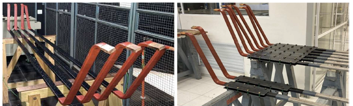
Figure 4 – Original CFSM hydro generator stator bars developed for inverter operation (left) and prepared with mounted steel plates as core simulation (right)
All bars are manufactured in VPI-technology with an effective insulation system of around 1.9 mm for the CFSM and 1.6 mm for the DFIM. The total length of the CFSM – bars is roughly 3500 mm with a taped CAT length of 2700 mm and about 5730 mm with a taped CAT length of 4100 mm for the DFIM. The related SGT’s are adjusted for the inverter operation to minimize the resulting electric and thermal stress during operation. To reduce the apparent power needed for testing, the IEC 60034-18-42 allows to shorten the CAT-length.
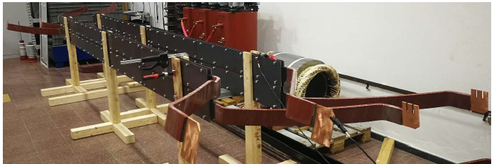
Figure 5 – Original DFIM hydro generator rotor bars with steel plates mounted in the mock-up
Therefore, for the CFSM – bars the full-size bars are cut in half and some CAT-length is removed. Finally, a new field grading system is established by semiconducting varnishes at the cut and stripped sides. In addition, the sample size is doubled, which gives more confidence for the qualification. The prepared test samples with mounted steel plates for core simulation are shown in Figure 4, too. For the qualification of the DFIM stress grading system the full-size rotor bars are tested in a simplified mockup, which is shown in Figure 5.
5.3. Test setup
For the qualification a self-developed inverter pulse generator is used [17]. It generates bipolar squarewave voltages with variable repetition frequency, impulse rise time and peak-to-peak impulse-voltage with an overshooting signal during the switching typically in the range of 2 – 10 %. The pictures in Figure 6 presents the test setup with the inverter pulse generator and the connected set of test samples. Due to the large capacitance of the DFIM – rotor bars of around 26 nF, the bars can´t be tested in parallel.
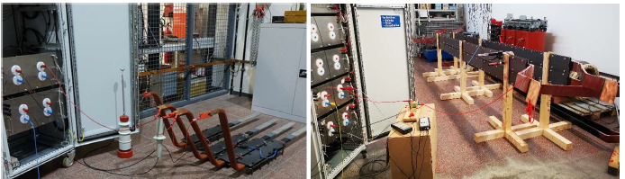
Figure 6 – Inverter pulse generator with connected CFSM – stator bars (left) and DFIM – rotor bars (right) mounted in the mock-up
By means of a HV-voltage probe the bipolar square-wave signal is analyzed with an oscilloscope. The screenshot in Figure 6 shows the voltage signal at the DFIM – rotor bar both for a longer duration (left) and a detailed view directly during the switching (right). The values for repetition frequency and peakto- peak impulse-voltage with applied load are measured permanently and can be adjusted in case of a potential deviation or drifting.
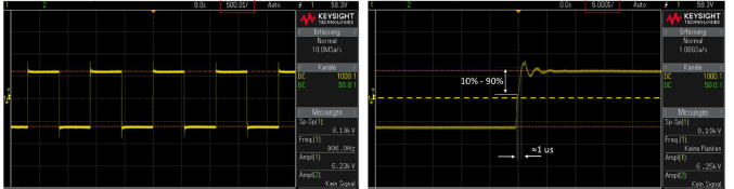
Figure 7 – Bipolar square-wave signal at the DFIM – rotor bar measured with an oscilloscope by means of an HV-voltage probe
The repetition frequency with ? ≈ 0.9 kHz and peak-to-peak impulse-voltage with meets the requirements presented in Table 3. Due to the large capacitive load the overshooting during the switching is clearly visible.
5.4. Acceptance criteria
Chapter 14.3 of the IEC 60034-18-42 describes the acceptance criteria to fulfill the qualification after the end of the 3rd ageing cycle with 100 h pulsed voltage. Any PD-activity visible during blackout test or by using an UV-camera must not be present. Figure 8 shows an example of failed stress grading system after the endurance testing. For this particular case, a picture taken with an UV-camera is also presented. Due to the continuous PD-activity in the stress grading area (left) the CAT is heavily deteriorated, which can be seen with naked eye (right).
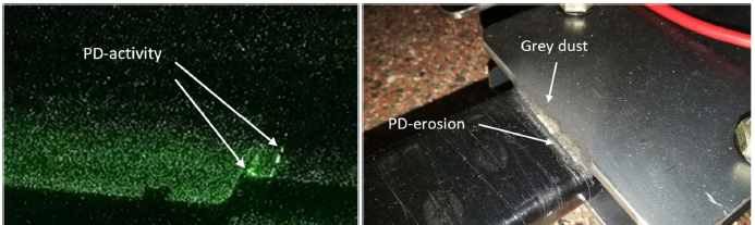
Figure 8 – Example of a failed stress grading system due to PD-activity observed via UV-camera (left) and visible deterioration at the slot-exit area (right)
Beside at the slot exit some PD-activity is also present further outboard indicating an issue at the transition between CAT and SGT.
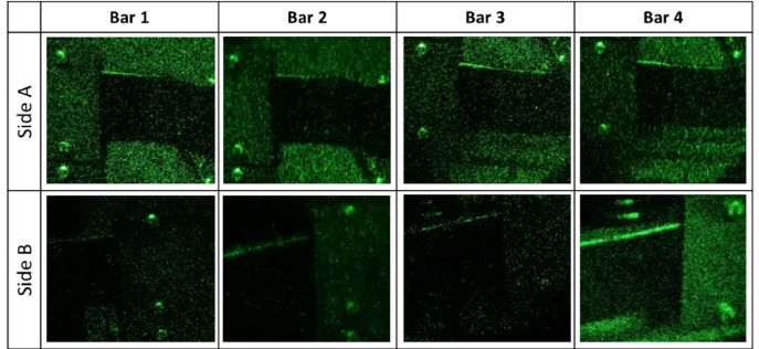
Figure 9 – Performance of the DFIM stress grading system without PD-activity observed via UV-camera
Figure 9 shows the stress grading system performance of the DFIM – rotor bars via UV-camera at the endurance testing end according to IEC 60034-18-42. No PD-activity is visible at all and therefor the qualification is finished successfully.
6. Additional measurements and evaluations
In addition to the qualification scope presented prior, further measurements are conducted to get a better understanding how the electric and thermal performance of the stress grading systems is influenced due to inverter operation. Therefore, direct field measurements and thermography are conducted and evaluated afterwards.
6.1. Electric behavior
Beside possible PD-activity on the CAT and SGT surface the electric behavior of the stress grading system can be assessed by means of field measurements [18].
The pictures in Figure 10 show the principle of measurement setup with an optical probe based on the Pockels effect. This enables the possible not only to determine the magnitude of the field strength along the surface in the stress grading area but also to perform this unidirectional, i.e., only measure the axial component of the field strength. The field probe is able to determine the electric field strength for both cases, inverter and normal power frequency operation.
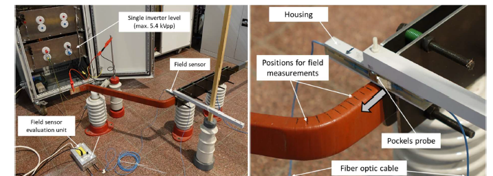
Figure 10 – Measurement setup for determination of the field strength at the insulation surface
Figure 11 presents the results of the measured axial field strength for a voltage of 7.7 kVRMS at 50 Hz (left) which is the design voltage for this insulation level. In addition, the result for an impulse voltage with a repetition frequency ? = 1 kHz is shown in the right-hand graph.
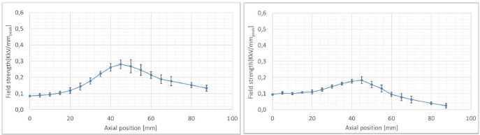
Figure 11 – Measured axial field strength for a voltage of 7.7 kVRMS at 50 Hz (left) and for an impulse voltage according to Table 2 (right) on the same specimen
Even though the applied voltage signals differ quite significant in shape and magnitude, the resulting axial field strength distribution is comparable and well below critical values. However, previous numerical simulations point that the critical field enhancement will occur directly at the slot exit during the switching with the high impulse rise time, which is difficult to measure [16].
Typically, partial discharge and dissipation factor measurements are performed periodically on the insulation system to assess the condition and identify potential failures during the lifetime of a rotating machine. Therefore, these measurements are conducted at 50 Hz and 0.1 Hz (VLF) during the qualification on the DFIM – rotor bars at specific points. As an example, the graphs in Figure 12 show the trending of the initial dissipation factor TanD0.2 and maximum TanD tip-up Max[ΔtanD] according to IEC 60034-27-3 Standard [19].
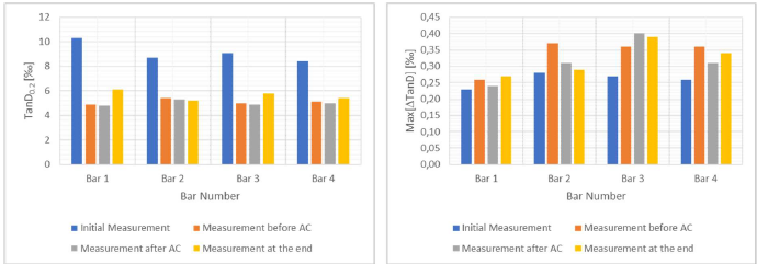
Figure 12 – Results of the initial dissipation factor TanD0.2 and maximum TanD tip-up Max[ΔtanD] at four different times during the qualification
From literature it is known, that a drop of the initial dissipation factor TanD0.2 indicates post-curing effects, which are quite common and also visible in the left-hand graph. After the drop from 1st to 2nd measurement the values are not changing significantly during the qualification. This does not indicate any signs of severe deterioration due to the electrical stressing during the qualification. The maximum TanD tip-up Max[ΔtanD] shows no clear trend in the trending of the values during the qualification. After an increase from 1st to 2nd measurement, which can also be explained by the decrease of the initial dissipation factor TanD0.2 due to post-curing, some bars have a slight increase of Max[ΔtanD] (bar 1 and 3), whereas the other two bars have no clear trending.
6.2. Thermal behavior
In contradiction to the electric behavior of stress grading system, such as the field strength distribution, the thermal performance of the CAT and SGT is quite different between power frequency and inverter operation. This is caused by the high displacement currents occurring during the switching with a high repetition rate and impulse rise time. Due to the notable resistivity of the CAT the highest current density is typically generated at the slot exit contact area and defines the location of the hot-spot temperature. This is the main difference to power frequency operation with a sinusoidal voltage, where the hot-spot occurs at the beginning of the SGT.
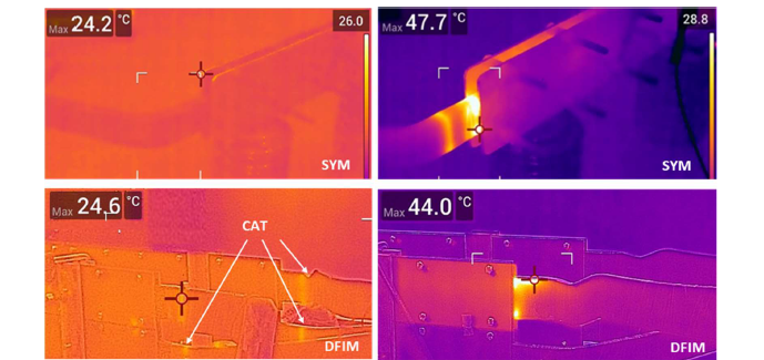
Figure 13 – Thermo-vision pictures taken from the CFSM and DFIM – bars during the 1000 h endurance testing with power frequency (left) and during impulse voltage testing with 1 kHz (right)
The thermo-vision pictures in Figure 13 highlights this phenomenon. The left-hand picture shows the temperature distribution during the 1000 h endurance testing (Part 2 of the qualification according to Table 2), the right-hand one the characteristics during impulse voltage testing. Clearly, the hot-spot directly at the slot exit, simulated with the steel plates, is visible. In addition, a second local hot-spot at the SGT-begin further outboard is notable for the CFSM.
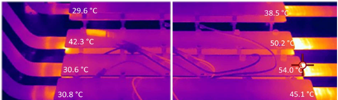
Figure 14 – Temperature profile of both CFSM slot-exit ends during impulse voltage testing with 1 kHz
Due to the low electric stress during power frequency operation almost no Joule heating is generated. Therefore, no clear hot-spot is present in the insulation. Only for the DFIM a very small increase of the temperature at the CAT end, where it overlaps with the SGT can be seen (bottom right picture).
Figure 14 illustrates the influence of the differences in CAT and SGT on the resulting temperature profile during the impulse testing parts. The left-hand picture shows the original stress grading system on the involute side. The characteristic two hot-spots are clearly visible. At the cut and stripped straight bar side (right-hand picture) the temperature profile looks quite different. This is caused by the new stress grading system applied after the VPI-process. Therefore, the resistance characteristic is quite different and results in higher slot-exit temperatures. It has to be pointed out, that this stress grading system is not relevant for the qualification process, because it is not part of the original bar design and only needed to prevent potential flashover during the endurance testing.
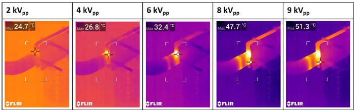
Figure 15 – Influence of the peak-to-peak impulse-voltage U'pk/pk for a fixed repetition frequency of 1 kHz on the slot exit hot-spot temperatures
Finally, the influence of the peak-to-peak impulse-voltage is discussed by means of Figure 15. For a given repetition frequency of 1 kHz the thermo-vision pictures for 2 kVpp (left) up to 9 kVpp (right) are shown. Considering an ambient temperature of about 22°C the increase in hot-spot temperature at 2 kVpp kV is only a few Kelvin, whereas at 9 kVpp it is almost 30 K. Due to the non-linear resistance characteristic of the SGT a notable temperature rise at the CAT increases significantly at higher peakto- peak impulse-voltage
.
7. Conclusions
A successful qualification of high voltage stress grading systems for stator and rotor insulation in accordance to IEC 60034-18-42 standard was performed. The developed inverter pulse source allows not only to generate the required bipolar square-wave but also to perform further parameter investigations on the resulting thermal and electric stress in the insulation system due to variable setting of repetition frequency, peak voltage and impulse rise time.
In general, a stress grading system performing sufficient under power frequency at sinusoidal voltage may behave totally different under impulse voltages and makes comprehensive investigations especially on hot-spot temperatures reasonable.
With regards to the presented dielectric measurements, i.e., dissipation factor, it can be concluded that either the aging during the qualification is not significant or the dissipation factor is not appropriate to assess the condition of the aged bars.
References
- History of Electricity - IER
- What are the Uses of Electricity in Modern Life
- Importance of electricity
- Electricity, an Essential Necessity in Our Life
- Benefits of Hydropower
- Hydropower benefits
- 10 Advantages of Hydropower
- https://www.alpintreff.de/regionen/100530-Kraftwerk-Limberg-I/
- https://www.verbund.com/de-at/ueber-verbund/kraftwerke/unsere-kraftwerke/kaprun-oberstufe
- T. Hildinger; Frades II- Europe’s Largest and Most Powerful Doubly Fed Induction Machine, HydroVision International, Charlotte, NC, USA, 2018
- IEC 60034-18-42:2017, Rotating electrical machines - Part 18-42: Partial discharge resistant electrical insulation systems (Type II) used in rotating electrical machines fed from voltage converters - Qualification tests, 02-2017
- J. Wheeler; Effects of Converter Pulses on the Electrical Insulation in Low and Medium Voltage Motors, IEEE Electrical Insulation Magazine (Volume: 21, Issue: 2, March-April 2005)
- E. Sharifi-Ghazvini; Analysis of Electrical and Thermal Stresses in the Stress Relief System of Inverter Fed Medium Voltage Induction Motors, PhD Thesis, University of Waterloo, Canada, 2010
- C. Staubach; T. Hildinger; A. Staubach; Comprehensive electrical and thermal analysis of the stress grading system of a large hydro generator, IEEE Electrical Insulation Magazine Volume: 34, Issue: 1, January-February 2018
- W. McDermid; Damage resulting from long term slot discharge activity in a hydrogen environment, IEEE International Symposium on Electrical Insulation, 1990
- C. Staubach; T. Hildinger; Stress grading system evaluation for a converter feed hydro generator winding, 2020 IEEE Electrical Insulation Conference (EIC), 2020
- R. Fischer-Baeumer et al; Application of a HV bipolar square-wave generator for qualification and assessment of energy equipment, 2022 24th European Conference on Power Electronics and Applications (EPE'22 ECCE Europe), 2022
- R. Merte; Measurements of electric fields with an electro-optic miniature probe, International Symposium on High Voltage Engineering ISH, Ljubljana, Slovenia, 2007
- IEC 60034-27-3:2015, Rotating electrical machines - Part 27-3: Dielectric dissipation factor measurement on stator winding insulation of rotating electrical machines, 12-2015