C3 - Circularity for high voltage equipment
Authors
Christophe PERRIER, Thomas BERTELOOT, Clémence DUMOULIN, Eliott PEREZ - GE Vernova, France

Summary
Materials such as copper, aluminium and tungsten are extensively utilised in high-voltage (HV) equipment due to their electrical specifications. These materials possess properties that make them ideal for application in the electrical sector. However, according to the study on the CRMs for the EU from 2023, these metals are classified as Critical Raw Materials (CRMs). They are, thus, economically, and strategically relevant for the European Union economy. Nevertheless, they also present increased supply risk. While the current supply chain is capable of meeting market demands for the time-being, there is an increased potential for exceeding capacity before the year 2030.
The electrical grid reinforcement is vital to decrease the energy sector greenhouse gases emission. As such, new solutions are required to ensure a strong delivery of HV equipment in front of potential shortages of raw materials. Recognizing this challenge, and anticipating this situation, Product Circularity is identified as one of the key solutions for the electrical grid manufacturing sector. Product Circularity lies in the heart of sustainable production. It aims at defining how companies approach the life cycle of its products, dramatically decreasing raw material extractivism as a consequence of inserting circular strategies and life cycle thinking into a product’s early design stages.
This article will delve into the definition of Product Circularity and its targets specially focusing on HV equipment, with emphasis on Power Transformers (PTs) and Gas-Insulated Switchgears (GIS).
In a first step, the CSR concept is introduced to propose a full picture of Product Circularity actions, benefits and implementation challenges. In this regard, while “Closing the loop” represents the common vision of Circularity (recyclability), “Slowing the loop” represents extending a product’s useful life; and “Reducing the loop” regards increasing the product’s mass efficiency.
In a second steps, PTs and GIS will be described with a focus on their various materials and their environmental impacts. Then, in a third part, product circularity actions with CSR concept will be proposed and discussed. The last part will be focused on how to quantify the benefits of recycling.
Keywords
Product circularity, high voltage equipment, critical raw materials, life cycle assessment1. What is circular economy?
Circular Economy disrupts linear development arrangements and seeks to integrate both economic and environmental interests, fostering sustainable growth through a holistic approach [1]. It focuses on three main pillars: Closing, Slowing and Narrowing loops [2].
- Closing the loop involves the reuse of products, components, and materials at the end-of-life stage. It mainly means reuse what was produced in the past i.e., reuse more than 50-years-old products for most of high-voltage technologies which will not come without great challenges about knowledge of materials of the past.
- Slowing the loop refers to prolonging the use of products and components. As long as a product on the Grid is suitable for safe, environmental and economic use, there is no need to change it by a new one. Numerous solutions are available on the market to foster lifetime of products through digital monitoring to effective maintenance solutions.
- Narrowing the loop refers to reduce material and energy required during manufacturing. While reducing the mass already was an effective solution to reduce the cost of the products, more Ecodesign actions could be undertaken to further reduce energy consumptions or materials waste generation during manufacturing, pushing for new solutions that may not be the most cost-effective ones.
Kirchherr & al. [3] conducted a review of 114 reports on Circular Economy, suggesting a consolidated and unified definition, which is adopted in the present study “an economic system that replaces the ‘end-of-life’ concept with reducing, alternatively reusing, recycling and recovering materials in production/distribution and consumption processes. It operates at the micro level (products, companies, consumers), meso level (eco-industrial parks) and macro level (city, region, nation and beyond), with the aim to accomplish sustainable development, thus simultaneously creating environmental quality, economic prosperity, and social equity, to the benefit of current and future generations”.
Mantalovas & al. [4] argue that this economic approach offers numerous benefits beyond environmental advantages. By embracing circularity principles, businesses can enhance their competitiveness, optimise energy and material use, and unlock new revenue streams by repurposing or selling materials that would otherwise be discarded as waste. The cradle-to-cradle concept is at the core of Circular Economy, which emphasizes the continuous use of materials within the system through multiple cycles (figure 1).
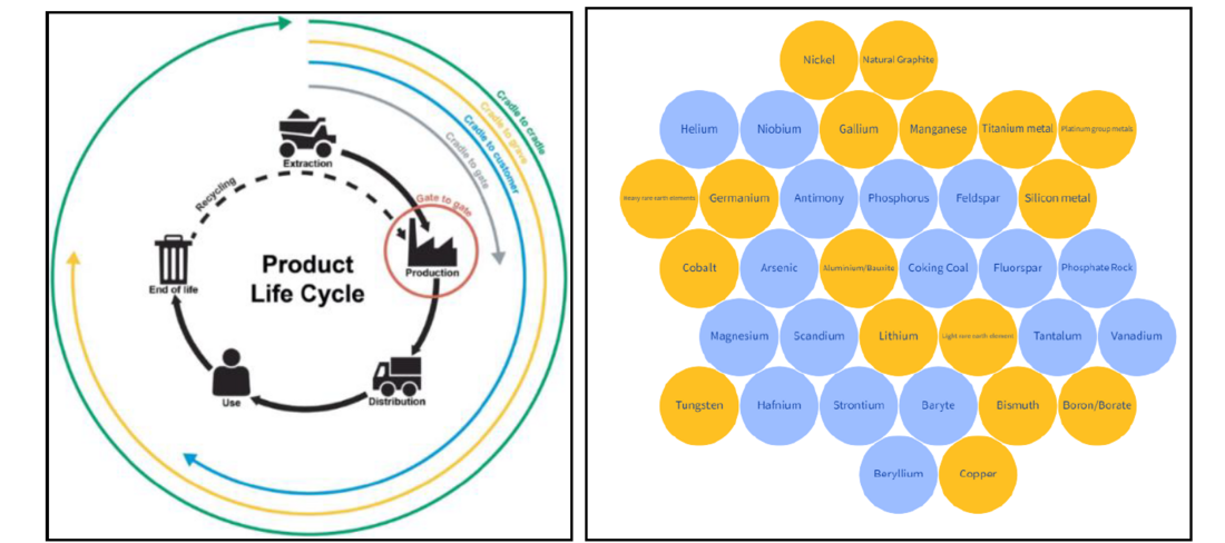
Figure 1 - LCA stages and scope (left) [5] and Critical Raw Materials (blue color) and Strategic Critical Raw Materials (orange color) for European Union [6]
It is even more relevant as numerous physical limits are being reached, especially regarding some raw materials that will not be enough available to satisfy the whole demand in the coming years.
In European Union, critical raw materials are raw materials of high economic importance, with a high risk of supply disruption due to their concentration of sources and lack of good, affordable substitutes [6]. On top of that, several materials were defined as strategic critical raw materials such as Copper, Aluminum and Tungsten, three well-known elements in high-voltage technologies (see figure 1).
From 2020 to 2050, in a high demand scenario, the request of some raw materials will burst like copper demand (x10) and aluminum demand (x6). It will induce strong prices increase and very likely shortages. Any HV product that delivers strong performances with efficient amount of copper and aluminum must be promoted in today designs.
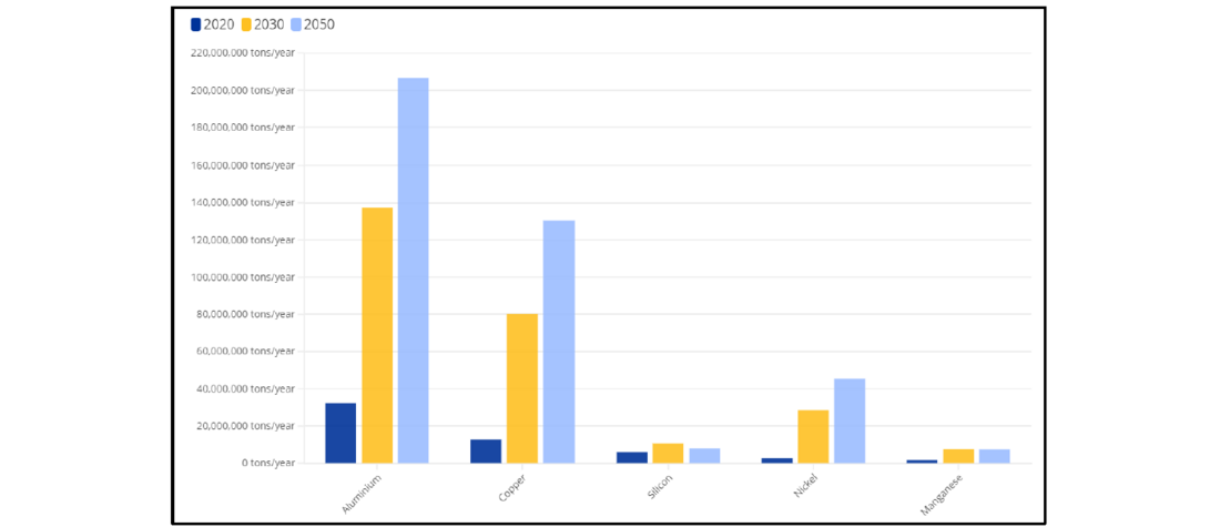
Figure 2 - Material demand in the European Union (high demand scenario) [6]
2. High voltage equipment
2.1. Power transformers
Power transformers are the enabling technology for the efficient transmission of electrical energy from where it is produced, whatever the primary source, to where it is needed wether by industry, railways or domestic consumers. Much of the basic technology used in transformers is quite mature and have existed for more than a century, but the design tools and manufacturing techniques are constantly improving and the range and capability of the finished product is constantly expanding, taking today into account the environmental considerations.
More particularly, a power transformer is a device that transfers energy from one electrical circuit to another by magnetic coupling without requiring relative motion between its parts. Its main role is to reduce the losses during electricity transmission by increasing the AC voltage. A transformer can have a power of few MVA to 1000MVA and a voltage from few kV to 1200kV AC. Transformer parts and components can be divided in two main groups: the active part and the passive part. The active part, immersed in insulating liquid, comprises the magnetic circuit, the windings, and their clamping structures. The passive part is needed in order to make the transformer functional, e.g. cooling equipment, protective equipment, and others fittings.
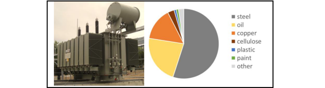
Figure 3 - Photo of a power transformer and average mass repartition of materials
As shown on figure 3, the main materials in a transformer are steel (including magnetic steel), cellulose for insulation (paper, pressboard and wood), copper, oil, porcelain, paint and plastics. All these materials appear in variable quantities according to the size and the type of transformer. Note that figure 3 is an average estimation of the mass distribution including all sizes of power transformers.
Life Cycle Assessment (LCA) of power transformers, from cradle to grave, indicates that the main impact is linked to the operation phase and the losses over 30 to 40 years of use, followed by materials as steel, copper and then oil [7, 8]. Figures 5 and 6 respectively show the LCA of a power transformer 63MVA/110kV with European electricity mix and a 300MVA/400kV with German electricity mix. The material impact distribution is also detailled in the figure 5 for the 63MVA transformer.
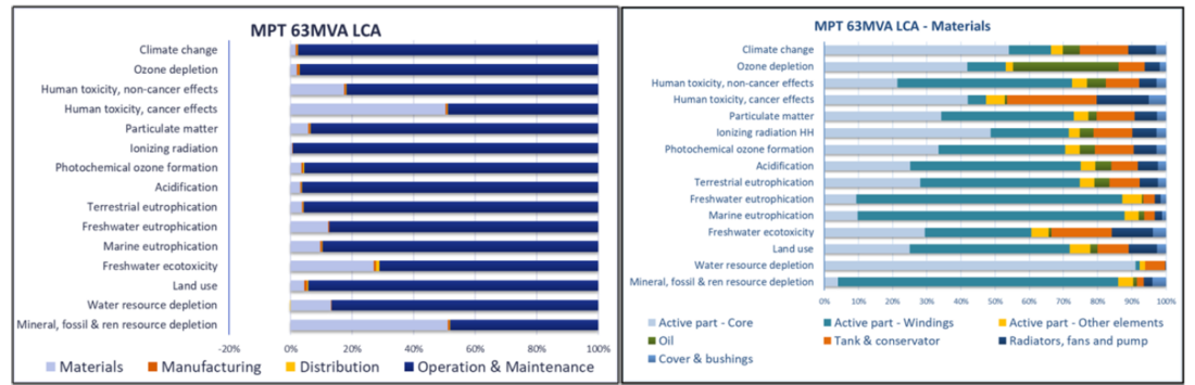
Figure 5 - LCA results (left) and material impact (right) for the power transformer 63MVA/110kV [7]
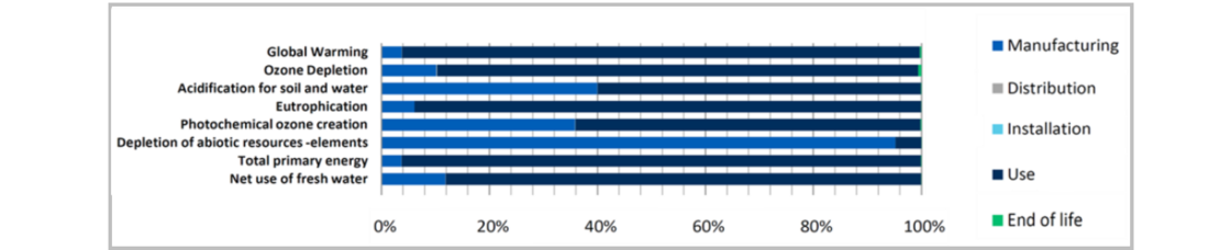
Figure 6 - LCA results for the power transformer 300MVA/400kV [8]
Because of the huge impact of transformer losses during the use phase, an European Eco design regulation [9, 10] was created to limit such impact with the Peak Efficiency Index (PEI). The equation for PEI determines the appropriate highest efficiency value of any transformer design at an optimal loading point, taking into account load losses, no load losses and accessories.
It is also important to point out that the use phase impact is particularly visible when the energy mix of the electricity production is impacting. As an example shown on figure 7, the climate change impact can drastically change depending on the energy production [11]. In Germany, production is mainly driven by coal [12] which means a greater impact compared to Denmark (dominated by wind) and France (dominated by nuclear). Then, in case where the energy mix has a lower impact (as renewable energies), the manufacturing phase is more significant, enhancing the importance of having recycled materials.
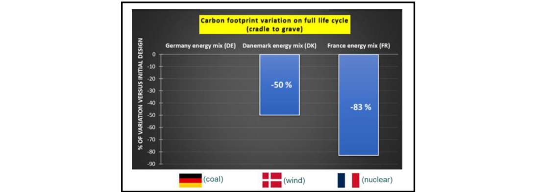
Figure 7 - Influence of energy mix on carbon footprint, variation (%) versus initial design in Germany [11]
2.2. Gas insulated substations
Gas Insulated Substations (GIS) are compact substations including circuit-breakers, disconnectors, earthing switches, instrument transformers and gas insulated busbars. They enable the protection of the electrical grid in case of fault, the quantification of electricity and the ability to adapt electricity pathways depending on grid requirements.
GIS are containing insulating gases under pressure in grounded metallic vessels which are designed to withstand pressure and carry current. Thanks to those grounded metallic vessels, a GIS is very compact making it suitable for areas where space is limited. The inner conductors are mainly made of aluminum and there are epoxy resin solid insulators to support those conductors as well as create partitions between GIS components. The structure is made of steel and the insulating gases are SF6, C4-FN mixtures, CO2/O2 or N2/O2 mixtures.
The main drawback of GIS technology is the use of huge amount of metal among with aluminum, which is a strategic critical raw material. There is more than 55% of aluminum in the composition of a 145kV GIS and more than 85% of metals (including aluminum, steel, and copper alloys) [13]. The main non-metal element is epoxy resin for the solid insulators (see figure 8).
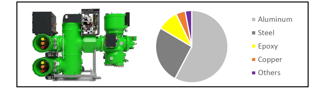
Figure 8 - Example of 145kV SF6-free GIS and Mass repartition of materials
The below figure 9 shows the LCA of a 420kV GIS with C4-FN mixture. It is underlined that the manufacturing is the most impacting phase on all impact categories (except ionizing radiation), mostly due to the big quantity of aluminium used in the device. Then, the use phase with electrical losses follows.
If a focus is made on manufacturing, the circuit breaker and the other elements are the main contributors, except on resource use, minerals and metals where copper (a critical raw material) is used in the windings of the current transformer.
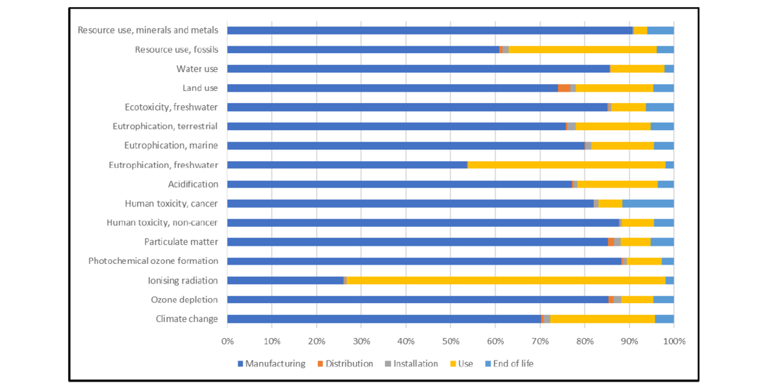
Figure 9 - LCA results for a 420kV GIS with C4-FN mixture
3. Product circularity – Proposed actions
3.1. Power transformers
For power transformers, the circular economy concept can be applied on different ways:
- Closing the loop may be achieved by using recycled materials, as copper and oil;
- Slowing the loop may be achieved by use of high-quality and durable materials but also lifetime extension through oil monitoring;
- Reducing the loop may be achieved by reducing the mass with optimized design.
3.1.1. Closing the loop
As shown previously on figure 5, copper is the most impacting of transformer materials. It is mainly explained because of the scarcity of this material which is going to become more and more important, and particularly because of the mines density reduction whereas industry production increases. The idea would be then to replace the primary copper in transformers by secondary copper. Nevertheless, copper used in transformer windings is required to have a low resistance (high conductivity) in order to minimize losses, and to be mechanically strong enough to resist all forces experienced during its lifetime; especially those created during short-circuit fault conditions. Some studies are then needed to check the suitability of secondary copper in new power transformers.
Another way of closing the loop in power transformers is to focus on the insulating liquid. Even if the liquid has clearly a lower environmental impact than the copper or the steel (figure 5), it has a significant contribution of around 20% in the total weight of the transformer. As shown on the figure 10, the recycled mineral oils obtained with the re-refining technology are really a good opportunity by having a significant reduction of all environmental impacts versus other transformer oil types. Such study was made in accordance with ISO 14040-14044 [14, 15], the methodology described in table I, and the support of an external consultant to collect the data. Note that this study is only considered as self-declaration and based on generic data over the world, to be used for discussion and not for comparison with other studies.
| Software | SimaPro version 9.4.0.2 |
|---|---|
| Data Base | Ecoinvent 3.8 |
| Calculation method | EF3.0 (16 indicators) |
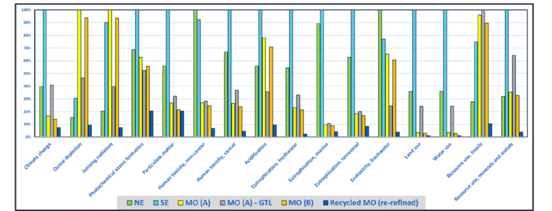
Figure 10 - LCA cradle to gate of different insulating liquids (NE = natural ester IEC 62770, SE = synthetic ester IEC 61099, MO = mineral oil IEC 60296 type A, B or recycled) in accordance with ISO 14040-44 [16]
3.1.2. Slowing the loop
Although transformers are very reliable devices with life duration of 30 to 40 years, there remains one inevitable type of failure called “end of life” failure mode. Most, if not all, organic materials used within the transformer are subject to aging processes which lead to the gradual degradation of their physical, chemical and electrical properties. The most important of these organic materials is the composite insulation system, i.e. cellulosic materials (mainly paper and pressboard) impregnated with insulating liquid. Three main processes drive the aging of cellulose/oil insulation systems [17]. First one, pyrolysis is initiated by the temperature as the main driving force behind the chemical reactions that cause ageing. The other processes are hydrolysis, initiated by the presence of water and oxidation, initiated by the presence of oxygen. The lifetime of the transformer is driven by the lifetime of the cellulosic insulation because this later cannot be easily replaced as the insulating liquid. Although the end of life failure is inevitable, the life of the cellulose can be maximized with careful monitoring through the oil, the aim being to apply mitigation techniques at the right time (maintenance, repair, upgrade, oil treatment, oil change, …). Among the different methods to assess the condition of transformer insulation, the main ones through the oil are:
- The measurement of different oil properties (electrical, physical, chemical) which gives an indirect indication of the transformer condition. Recommendations are given in the IEC 60422 [18] for mineral oils, IEC 61203 [19] for synthetic ester and IEC 62975 [20] for natural ester.
- The measurement of dissolved gases in the oil (DGA) which gives an indication of possible electrical or thermal faults in the transformer according to IEC 60567 [21] and IEC 60599 [22].
- The humidity equilibrium curves which gives an indication of the cellulose humidity through the oil [23], knowing that humidity is a sign of degradation, not recommended in electrical insulation.
- The detection of cellulose ageing markers as furanic compounds according to IEC 61198 [24] for severe degradation or Methanol according to IEC TR 63025 [25] and detectable at earlier stage of the degradation.
The previous list is not exhaustive but underlines that oil monitoring is an efficient way to improve lifetime extension of power transformer and thus their circularity.
3.1.3. Reducing the loop
Reducing the loop could be achieved by manufacturing a transformer with optimized design and lower weight, and then lower environmental impacts linked to the materials. Nevertheless, for such optimization, it is needed to check that there is no pollution transfer.
For that purpose, comparative calculations and analysis were carried out with same materials and same components for different 300MVA designs [8]. Five different designs were compared: LCA original (figure 6), design with lower insulation margins (accepted rule of IEC 60076-3), design with higher no load losses, higher load losses and finally higher losses not in line with eco-design regulation [9, 10].
The figure 11 below represents the weight variation of copper and magnetic steel for the different designs versus the PEI, dotted line being the minimum value to be reached for a 300MVA transformer. It is clearly observed that by reducing the weight and the size of the transformer, the efficiency of the transformer is also reduced (higher losses). By going deeper in the analysis with the figure 12, focused only on the carbon footprint (climate change/GWP impact), it is highlighted that reducing the weight will save carbon emissions during manufacturing phase (cradle to gate) but on the other hand will significantly increase the carbon emissions during the use phase with the higher losses (decrease of PEI). The main message of these results is that for power transformers, a right balance is needed between material and efficiency and reducing the loop is not so easy.
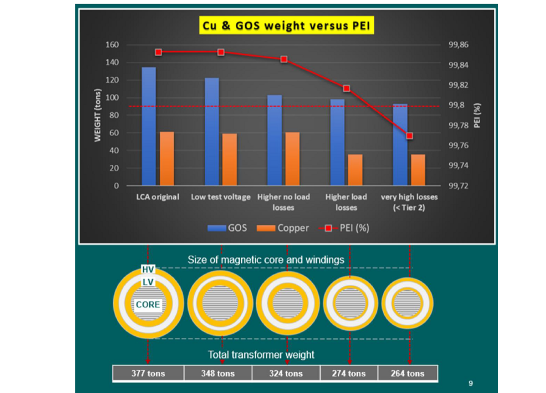
Figure 11- Peak Efficiency Index (PEI) and weight variation of copper (Cu) and magnetic steel (GOS) versus different transformer designs [11]
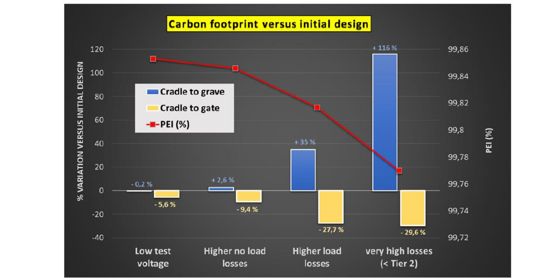
Figure 12 - Peak Efficiency Index (PEI) and carbon footprint variation from cradle to gate and cradle to
grave for different transformer designs of 300MVA versus the initial design (figure 6) [11]
3.2. Gas insulated substation
For GIS, the circular economy concept can be applied with following examples:
- Closing the loop may be achieved by using recycled materials, as aluminum and steel;
- Slowing the loop may be achieved by replacing SF6 with C4-FN mixture in GIS installed base;
- Reducing the loop may be achieved by selecting low waste manufacturing processes.
3.2.1. Closing the loop
M. Perret & al. [13] already described the great interest to use recycled aluminum in GIS products to reduce the carbon footprint during manufacturing stage. Indeed, for SF6-free GIS, aluminum is the first driver for carbon footprint. It is even more true having in mind that it is a Strategic Critical Raw Material.
However, it must be pointed out that the recycling industry for aluminum in high-voltage technology does not exist yet. The main reason is that most of GIS are still operating and very few are decommissioned or being decommissioned. The amount of available aluminum from GIS is also very small compared to other industries and to recycle a 100% GIS scraps batch may not be economically relevant. To use recycled aluminum looks feasible, to use 100% recycled aluminum coming from an old GIS may never be possible. The “mass balance sourcing” [26] could however be relevant for our industry: the masses of secondary materials coming to factories are tracked while the products going out of the factories contain a mix of secondary and primary materials with no tracking.
Challenges for GIS will be to properly sort of the materials, to avoid contaminants as much as possible such as coatings and to validate mechanical and electrical properties on long-term range. GIS requires low resistivity to maintain low losses, static mechanical loads with gas under pressure as well as strong dynamic mechanical loads for some compartments such as circuit-breakers. It will be important to ensure that pollutant in recycled aluminum such as iron will not impair any of those properties.
3.2.2. Slowing the loop
A great majority of installed GIS contains SF6 gas that will be forbidden in coming years in the European Union and hopefully in the rest of the World. SF6 gas is indeed the worst greenhouse gas ever. To replace SF6 gas without a full dismantling of the GIS, a solution is to use strong dielectric gases with much lower impact on carbon footprint such as C4-FN mixtures: SF6 is removed, some parts are adapted (manometers and molecular sieves), then C4-FN mixture gas is injected.
The second LIFE project funded by European Union LIFE program since 2022 [27] aims at removing SF6 in GE 420kV GIS substations in most of the compartments. It will be a first step towards potential removal of SF6 in most of GE legacy SF6 GIS compartments.
The benefit on resources use is clear: an SF6-free GIS is obtained by adding a very limited mass of new parts instead of removing the great amount of aluminum already installed.
3.2.3. Reducing the loop
On top of well-known mass decrease thanks to a better understanding of physical phenomena and improved design rules, new set of principles shall be considered to deliver more sustainable designs for better use of resources.
A first principle is to deeply understand manufacturing processes and associated material wastes. There are material losses in all manufacturing processes, such as those generated by machining. These losses vary depending on the manufacturing process used. It is therefore important to take into account the surplus of material to be manufactured to obtain the desired final part, as well as the treatment of this waste. As an example, below losses can be associated to the aluminium used in GIS: 24-25% for extrusion/rolling [28], 23% for machining [29] and 35% to 48% for castings [30].
Those figures are generic ones and one must keep in mind that:
- They will greatly differ from one supplier to another. The quality of the supplier process will become key and can only be assessed by audit / partnership to understand how to decrease amount of material wasted during manufacturing.
- They will greatly depend on what become the waste. For instance, in case they are directly reinjecting in an oven for casting another same part, they cannot be considered as waste. Again, strong audit / partnership must be undertaken to build strong data.
- They will greatly depend on quality of final part. A good manufacturing process must avoid poor quality parts that will become scrap before any use.
As a last comment, 3D-printing delivers light parts and can be viewed as a highly efficient manufacturing process from mass use point of view. However, a fair assessment of quantity of waste during manufacturing process must be done before any conclusion.
A second principle to consider is the right use of right material for each application. Once designers are aware of some materials to avoid (such as strategic critical raw materials or very high carbon content material) they must review their habit and select a less impacting one:
- Copper could be replaced by steel in some grounding links, in case safety is not impaired;
- PTFE could be replaced by steel in some high temperature areas of circuit-breakers;
- Aluminum could be replaced by steel where no current runs.
Most of the choices were driven by economical choices in current designs due to competitions between OEMs and poor environmental considerations in most of the tendering processes: they will now also be driven by sustainable choices thanks to more and more sustainable criteria in tendering processes.
4. How to quantify benefits of recycling?
The recycling of materials at end-of-life of a product enables to limit the extraction of Raw Materials (RM) for a next product, and thus remove the impacts related to the manufacture of RM. Figure 13 shows an example of three products using the same material: Previous Product, Studied Product and Subsequent Product.
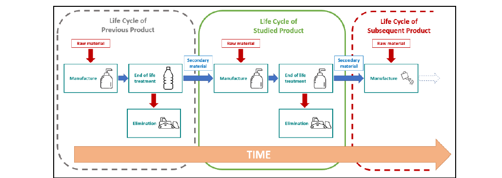
Figure 13 - Three products using partly the same material
At the end of its life, the bottle (Previous Product) will be partially recycled. Its recycled material will serve as a secondary material for the soap bottle (Studied Product). At the end of its life, some of the material will be recycled and used as a secondary material for the watering can (Subsequent Product).
When quantifying environmental impacts of Studied Product, it is important to clearly define who benefits from the use of secondary materials from Previous Product and who will be charged for the recycling of the materials for Subsequent Product. To use secondary materials is indeed most of the time an improvement from environmental point of view and the avoided impacts and loads must be properly attributed.
4.1. Negative impacts do not exist
While some LCA consider that there is a “benefit” / “negative offset” for environmental impacts of a studied product thanks to recycling, this approach is not physical. There is no “removal of impacts” at end-of-life of a product and a negative offset is not relevant.
Moreover, this “benefit” / “negative offset” shall not hide a strong impact during manufacturing and use phase of long lifespan products such as high-voltage products. It is especially true regarding Greenhouse Gas (GHG) Emissions. Having a 40-year-lifespan, to rely on recycling at end-of-life of the product installed in coming decade is not relevant to reduce GHG emissions before 2050.
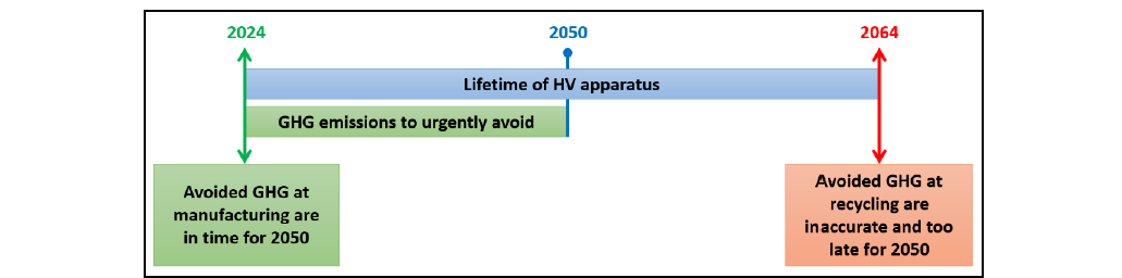
Figure 14 - GHG emissions must be done before 2050
For High-Voltage products, the recycling at end-of-life, much after 2050, cannot be considered as a benefice. What matters is the use of secondary materials at manufacturing stage, much before 2050.
4.2. Substitution point
Between two systems, a substitution point must be defined. The substitution point is the limit between two systems to allocate the charge of the recycling process to obtain secondary material. Depending on the standard, such as Product Category Rules (PCR), this point is defined differently. It can be located from the end of dismantling of a previous product up to the beginnig of manufacturing of the next one.
In our case, we apply the “Polluter Pays Principle” : all impacts related to preparation of secondary materials must be charged to the studied product. Next product is only charged with the transportation of secondary material.
4.3. Example for casted aluminium
Aluminum is a Strategic Critical raw material for European Union. Indeed, on Tuesday 12th of December 2023, the European Parliament approved the text of the Critical Raw Material Act [31].
As it is also the main contributor for carbon footprint at manufacturing of a GIS (see § II.2), the use of secondary aluminum is key to decrease carbon content of GIS. An example of carbon footprint for casted aluminum parts is provided in figure 15 and was performed with test methodology described in table II.
| Software | SimaPro version 9.4.0.2 |
|---|---|
| Data base | Ecoinvent 3.8 |
| Calculation method | IPCC 2021 |
There are two hypothetic cases ranging from full primary material to full secondary material: suppliers provide something in between. During manufacturing process of a casted aluminum part, it is important to consider:
- Impact of the raw material from primary (extraction, treatment, transformation, transportation) and from secondary (transportation);
- Impact of the manufacturing process: manufacturing waste, energy consumption, …;
- Impact of waste treatment.
Point of substitution is located after delivery of secondary aluminum ingots. It means that the impacts to make those ingots is allocated to the previous product, according to the Polluter Pays Principle.
The impact allocated to the studied product using secondary aluminum is the transportation of the ingots. The impact to make again secondary materials at its end-of-life is also considered.
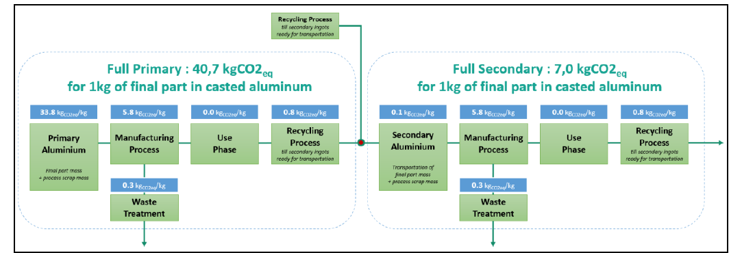
Figure 15 - example of carbon footprint for 1kg of casted aluminium final part
From our hypothesis, to make 1kg of casted aluminum part ranges from 40,7 kgCO2eq/kg with full primary material to 7,0 kgCO2eq/kg with full secondary material. Of course, it depends on actual location of manufacturing steps, and those numbers could be lower considering low carbon energy mix factories. It is however important to get in mind that a null impact does not exist.
4.4. Importance of certification
As the content of secondary material is key to deliver a proper evaluation of carbon footprint during manufacturing, it becomes urgent to settle certification programs to ensure quality of material used for manufacturing of parts.
It is in everyone interest to avoid too optimistic LCA:
- To better evaluate all GHG emissions that are not directly related to the manufacture of the product, but to other stages of the product life cycle (supply, transport, use, end of life, etc.).
- To ensure a fair competition during tendering stage.
It is even more relevant in a very global supply chain with difficult vision on materials and scraps origins
5. Conclusion
As shown through this article, circularity of high voltage products as power transformers (PTs) and gas insulated substations (GIS), can be achieved with the CSR concept.
Closing the loop is mainly driven by the potential use of recycled materials as copper and aluminium, respectively for PTs and GIS, which constitutes the main impact in the manufacturing phase.
Slowing the loop for power transformers is possible with careful monitoring of the oil and supported by several IEC standards, but also by replacing SF6 with C4-FN mixture in GIS installed base.
Reducing the loop may be achieved by optimizing the size without generating pollution transfer as it is observed for power transformers and the right balance is needed between use phase impact (losses) and material impact. The selection of low waste manufacturing processes is also a good way and particularly interesting for aluminium used in GIS.
The benefits of recycling can be calculated in many ways and it becomes urgent to define some standardized quantification rules by product category.
References
- O. Fitch-Roy, D. Benson, D. Monciardini, “Going around in circles? Conceptual recycling, patching and policy layering in the EU circular economy package”, Environmental Politics, Vol. 29, issue 6, 2020.
- J. Konietzko, N. Bocken, E. J. Hultink, “Circular ecosystem innovation: an initial set of principles” Journal of Cleaner Production, Vol. 253, April 2020.
- J. Kirchherr, D. Reike, M. Hekkert, “Conceptualizing the circular economy: an analysis of 114 definitions” Resources, Conservation and Recycling, Vol. 127, December 2017.
- K. Mantalovas, G. Di Mino, “Integrating circularity in the sustainability assessment of asphalt mixtures. Sustainability Journal, Vol. 12, issue 2, January 2020.
- S. Suppipat & al., “Designer’s guide for Life Cycle Assessment, Design for enhancing eco-efficiency of energy-related products”, Book series, Nov. 2022.
- https://www.consilium.europa.eu/en/infographics/critical-raw-materials, 25th Jan. 2024.
- E. Laruelle, C. Perrier, F. Devaux, “Circularity design of power transformers”, REE Magazine, n°2, 2020.
- C. Perrier, M. Chomel, J. Harthun, T. Stirl, “Life cycle assessment of power transformers”, Matpost Conference, November 22nd to 24th, 2023.
- Comission Regulation (EU) No 548/2014 of 21 May 2014 on implementing Directive 2009/125/EC of the European Parliament and for the council with regard to small, medium and large power transformers.
- Commission Regul. (EU) 2019/1783 of October 2019 amending Regul. (EU) No 548/2014.
- C. Perrier, “Life cycle assessment of power transformers”, Oral presentation at Matpost conference, session 7, November 22nd to 24th, 2023.
- Data from electricity maps, https://app.electricitymaps.com, August 2023
- M. Perret, M. Chomel, S. F. Vantil, C. Dumoulin, C. Cocchi and T. Berteloot, “Remaining levers to reduce the climate change impact of today's SF6-free high-voltage equipment,” in Symposium Advanced Technologies in Electrical System (SATES), Arras, France, 2023.
- ISO 14040:2006, “Environmental management – LCA – Principles and framework”.
- ISO 14044:2006, “Environmental management – LCA – Requirements and guidelines”.
- J. Sulpice, “Life Cycle Assessment of different insulating liquids for power transformers” Internship report, GE Vernova, December 2023.
- CIGRE Technical Brochure n°738, “Ageing of liquid impregnated cellulose for transformers”, 2018.
- IEC 60422:2013, Ed. 4, “Mineral insulating oils in electrical equipment – Supervision and maintenance guidance”.
- IEC 61203:1992, Ed. 1, “Synthetic organic esters for electrical purposes – Guide for maintenance of transformer esters in equipment”.
- IEC 62975:2021, Ed. 1, “Natural esters - Guidelines for maintenance and use in electrical equipment”.
- IEC 60567:2023, Ed. 5, “Oil-filled electrical equipment - Sampling of free gases& analysis of free and dissolved gases in mineral oils and other insulating liquids – Guidance”.
- IEC 60599:2022, Ed. 4, “Mineral oil-filled electrical equipment in service – Guidance on the interpretation of dissolved and free gases analysis”.
- C. Perrier, M-L. Coulibaly, J. Lukic, V. Mandic, “Ageing phenomena of cellulose/oil insulation in natural ester and mineral oil” paper A2-302, CIGRE conference Paris, 2014.
- IEC 61198:1993, Ed. 1, “Mineral insulating oils – Methods for the determination of 2-furfural and related compounds”.
- IEC TR 63025:2021, Ed. 1, “Insulating liquids – Quantitative determination of methanol and ethanol in insulating liquids”.
- https://www.rainforest-alliance.org/business/certification/what-is-mass-balance-sourcing/
- European commission, “Solutions for ECO-friendly and ECOnomically viable deletion of SF6 in operating GIS”, LIFE 3.0 - LIFE22-CCM-FR-SECO2ND-LIFE-GIS/101113840 (europa.eu)
- Allwood, Cullen et al., “Mapping the global flow of aluminium: from liquid aluminium to end-use goods”, Environmental Science & Technology, University of Cambridge, 2013
- Ecoinvent, Ecoquery. Market for aluminium removed by milling, average, https://ecoquery.ecoinvent.org/3.10/cutoff/dataset/5453/documentation, 2014.
- Ecoinvent, Ecoquery. casting, aluminium, lost-wax, https://ecoquery.ecoinvent.org/3.10/cutoff/dataset/11918/documentation, 2021.
- https://data.consilium.europa.eu/doc/document/ST-15686-2023-INIT/en/pdf