B4 - Overvoltages experienced by Metallic Return Cables in Bipolar HVDC Configuration
Authors
Max GOERTZ, Simon WENIG, Daniel BARTH - Mosaic Grid Solutions, Germany
Simon BECKLER - TransnetBW, Germany

Summary
The bipolar configuration with dedicated metallic return will be used in many future high voltage direct current (HVDC) projects worldwide. Several European transmission system operators have awarded framework cooperation agreements to deliver the next generation of HVDC systems. This new HVDC generation can transmit up to 2 GW active power at ±525 kV dc voltage and is based on modular multilevel converter (MMC) technology and HVDC cables with extruded insulation. In these projects, metallic return cables are intended to ensure that the HVDC scheme can continue to operate at half of its rated active power in the event of a cable fault. The current testing recommendation for HVDC cables leaves the specification of testing levels for metallic return cables open for the customer-supplier negotiation process. Therefore, this paper investigates overvoltages on metallic return cables in bipolar MMC-HVDC schemes and considers a potential realization concept for the next HVDC generation. Large parametric studies are conducted in order to provide an indication of overvoltages levels on metallic return cables. Occurring overvoltages are strongly dependent on the manufacturer-dependent design of the converter station. The main important design parameters with regard to overvoltages on metallic return cables are the grounding concept of the neutral bus and the design of the neutral bus surge arresters. Results of the paper provide a common understanding of the bipolar HVDC configuration and are especially relevant for the insulation coordination of metallic return cables.
Keywords
Bipolar MMC-HVDC, half-bridge, insulation coordination, metallic return cable1. Introduction
During the past decade, the symmetrical monopolar configuration represented the prevailing configuration for high voltage direct current (HVDC) schemes utilizing the modular multilevel converter (MMC) topology. Consequently, many publications authored by utilities, manufacturers or third parties are dealing with the transient electrical cable stresses in symmetrical monopolar configuration [1], [2], [3]. Moreover, the CIGRE working group B4/C4/B1.73 conducted extensive parametric studies and synthesized an overvoltage waveshape that is representative for schemes operating in symmetrical monopolar configuration [4]. Apart from the technically mature symmetrical monopolar configuration, the bipolar HVDC configuration gains strong attention due to an increasing demand for higher power transmission capacities. Figure 1 provides an overview of typical design concepts of bipolar HVDC schemes.
The rigid bipolar (RBP) configuration (left side in Figure 1) is not equipped with a dedicated metallic return cable. Obviously, the RBP configuration does therefore not provide redundancy in case of cable failures. Several MMC-HVDC schemes in RBP configuration are currently in planning or already in operation phase [5]. With regard to transient cable stresses, there are a few publications [6], [7], [8] indicating that cable overvoltages occurring in RBP configuration are significantly lower than the ones in symmetrical monopolar schemes.
In order to achieve a higher level of redundancy compared to RBP schemes, the bipolar configuration with dedicated metallic return (DMR) is foreseen for dozens of upcoming HVDC projects [9], as exemplified in Figure 1 (right side). Publications with a focus on transient cable stresses in bipolar configuration with DMR and in particular with a focus on metallic return cables are very rare due to limited project and operational experience of such schemes. The recently revised testing recommendation for HVDC cables with extruded insulation CIGRE TB 852 leaves the specification of testing levels open for the customer-supplier negotiation process [10]. Moreover, [10] states that system calculations, taking into account the different fault scenarios, should be performed by the supplier to determine the relevant temporary overvoltages occurring along the return cable. This paper is intended to facilitate a better understanding of voltage stresses occurring along metallic return cables. Basic design aspects in bipolar configuration with DMR are discussed and a parametric study is conducted by means of EMT-software to analyze the cable voltage stresses. The findings of this paper are relevant for the insulation coordination of metallic return cables. Obtained results provide a profound basis for the coordination processes between HVDC link owners, cable suppliers and converter manufacturers in future projects.
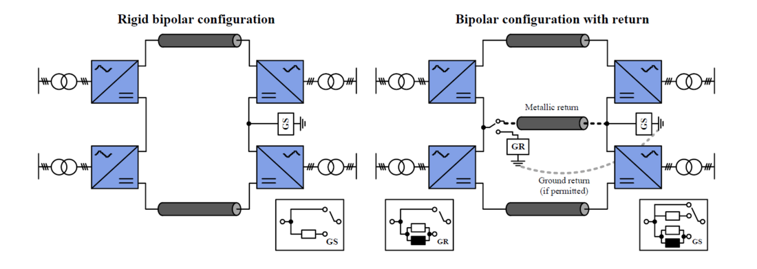
Figure 1 - Bipolar HVDC configurations
2. Overview of bipolar schemes with metallic return cables
2.1. Current Grid Planning Situation in Europe
Bipolar MMC-HVDC schemes with dedicated metallic return are foreseen as the backbone for the future European power system. Triggered by the ambitious offshore wind integration goals and the need for significant shorter project execution times, several European transmission system operators (TSOs) are aiming to standardize the next generation of MMC-HVDC systems. The so called 2-GW-standard foresees ±525-kV-cable systems with extruded insulation and is based on MMC-HVDC technology comprising half-bridge submodules. Several TSOs have already awarded framework cooperation agreements to deliver 2-GW-HVDC schemes in the next decade. Based on the German grid development plan, more than 30 new HVDC-systems of the 2-GW/±525-kV-standard are needed until the year 2045 [9]. The cable route lengths of these schemes lay in the range between 250 km up to 900 km [9]. In these future 2-GW/±525-kV-HVDC systems, the metallic return cable ensures that the HVDC system can continue to operate at 50 percent of its rated active power in the event of a cable fault.
2.2. System Description
Figure 2 shows the considered bipolar HVDC scheme. The dedicated metallic return cable is connected to the neutral bus at both stations. As permanent earth currents are prohibited in Europe, the neutral bus is earthed at a single station only (in the following grounding is applied at station 2). The grounding concept (indicated by G) as well as the neutral bus arresters (NBA) represent the key influencing factors for the electrical stresses of the metallic return cable. Both design parameters are further discussed within the next sections. The investigated HVDC scheme is a point-to-point connection and represents a potential realization concept of the 2-GW/±525-kV-standard. Corresponding system parameters can be found in Table 3 in the Appendix. A HVDC cable system with a route length of 700 km feasible for land installation is considered.
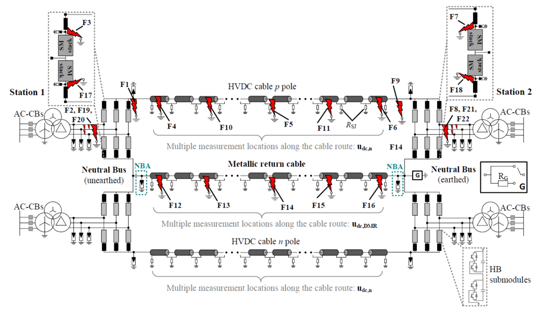
Figure 2 - Schematic of investigated bipolar HVDC configuration with metallic return cable
2.3. Operating Modes of Bipolar Schemes with Dedicated Metallic Return
Table 1 shows possible operating modes feasible for active power transmission in bipolar schemes with dedicated metallic return. With regard to the transient electrical stresses of return cables, bipolar as well as monopolar operation represent relevant operating modes. If a cable fault occurs during bipolar operation of the scheme, the healthy dc pole shall remain in operation while the converters of the faulty dc pole shall block their IGBTs and trip the ac circuit breakers. Consequently, the load current of the faulty dc cable commutates to the metallic return cable. During maintenance of a converter pole or during repair of HVDC pole cable, the scheme can operate in asymmetrical monopolar operation. If a fault occurs during monopolar operation, the converters of the remaining HVDC pole block their IGBTs and power transmission of the link is lost. Both scenarios, namely the occurrence of faults either in bipolar operation or in asymmetrical monopolar operation are further investigated within this paper.
| Station1 | Station 2 | Metallic return cable | |||
|---|---|---|---|---|---|
| Pole p | Pole n | Pole p | Pole n | ||
| Bipolar operation | coupled | coupled | coupled | coupled | coupled |
| Rigid bipolar operation | coupled | coupled | coupled | coupled | decoupled |
| Monopolar operation pole p | coupled | decoupled | coupled | decoupled | coupled |
| Monopolar operation pole n | decoupled | coupled | decoupled | coupled | coupled |
3. Basic design considerations in bipolar configuration
3.1. Grounding Concept
In bipolar MMC-HVDC schemes equipped with half-bridge submodules, the grounding concept of the neutral bus represents a key design compromise between permissible fault current stresses and overvoltage limitations, as described in greater detail in [6], [7], [11]. For the design of the grounding concept special consideration have to be laid on single phase-to-ground faults on the transformer valve side (Fault F8 in Figure 2). Figure 3 shows a simplified equivalent circuit of the affected converter pole after IGBT blocking. During F8, the fault current is fed from the ac grid, while the fault current path is through the applied grounding concept RG of the neutral bus, the anti-parallel diodes installed in the negative arms of the healthy ac phases, the transformer windings and the fault impedance. The challenge of this fault is that the currents flowing through the ac circuit breakers located on transformer grid side can consist of a significant dc component which might prevent the circuit breakers from clearing the fault. Figure 4 shows the fault currents on transformer grid side for different grounding concepts. Solid grounding (RG = 0.7 Ω) as well as grounding through an additional resistor RG are investigated. As clearly depicted, an absence of current zero-crossings in two ac phases can be observed for a solidly grounded neutral bus. An additional grounding resistor in the range of RG = 30 Ω leads to lower short circuit currents, mitigates the dc component and provokes current zero-crossings on transformer grid side. However, an additional grounding resistor RG also leads to higher cable overvoltages during other fault events, as discussed later in the paper. But, also for solidly grounded schemes, other measures exist to ensure current zero-crossings. As mentioned in [12], [13], the installation of auxiliary earthing breakers with grounding resistors enables the option to perform an additional three-phase short-circuit during F8 that provokes current zero-crossings in the ac circuit breakers. For commercial applications, both grounding concepts, either solid grounding (RG = 0.7 Ω) or grounding through an additional grounding resistor in the range of RG = 30 Ω are feasible. Therefore, both grounding concepts are further considered and compared within this paper.
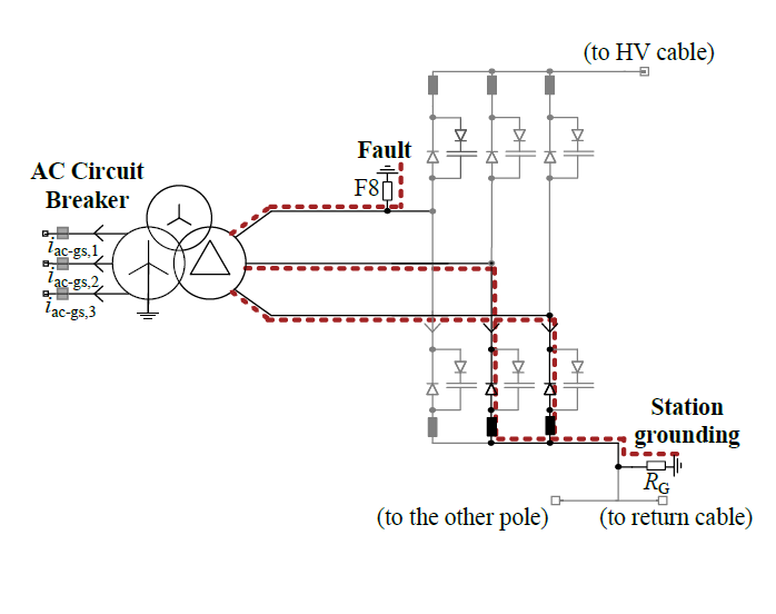
Figure 3 - Simplified equivalent circuit of the affected converter pole and exemplary fault current paths during fault F8 (after IGBT blocking) [6]
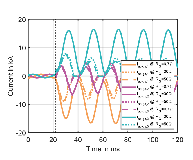
Figure 4 : AC currents iac-gs on transformer grid side during fault F8 for different grounding concepts of the neutral bus. Grounding Resistor: RG
3.2. Control and Protection of the Unaffected Converter Pole during Cable Faults
The impact of an additional grounding resistor RG on the transient system behavior of the bipolar scheme is briefly outlined for the cable fault F5 (fault in the middle of the cable, see Figure 2). The fault occurs at time T1 and affects the cable of the positive dc pole. The converters of the affected dc pole block their IGBTs and trip their corresponding ac circuit breakers. AC circuit breakers have cleared the fault at time T2. Due to the bipolar operation mode, the healthy dc pole shall remain in operation. Figure 5 depicts relevant converter internal quantities of the healthy dc pole (neg. dc pole) at station 2.
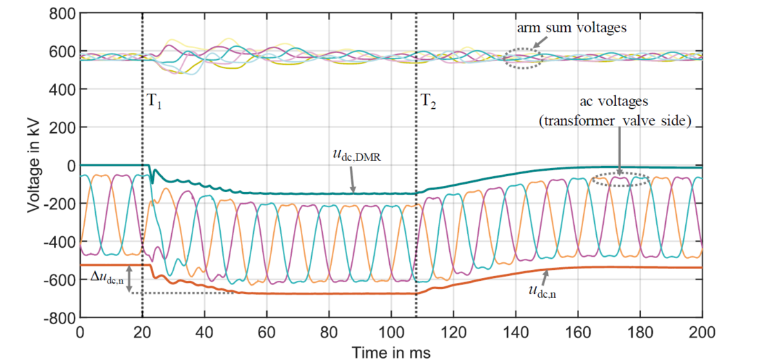
Figure 5 - Relevant converter internal quantities of the negative dc pole at station 2 during a HVDC cable fault at the positive dc pole (F5). Grounding resistor at station 2: RG = 30 Ω, pre-fault operating mode: bipolar operation
The voltage udc,DMR at the neutral bus of station 2 (measured at the cable termination of the metallic return cable) shifts due to the fault current through the grounding resistor RG. The voltage shift decays after the ac circuit breakers have cleared the fault at time T2. The neutral bus voltage is limited by the switching impulse protective level (SIPL) of the neutral bus arresters (NBA). The dc pole to ground voltage udc,n at the healthy dc pole (measured at the cable termination) experiences more or less the same voltage shift as the neutral bus and rises approximately to |1.3 p.u.| of rated dc voltage. The converter of the healthy dc pole stays within permissible operating conditions. The arm sum voltages shown in Figure 5 are an indicator for the internal converter energy and stay within their safe operating area. Further, the options for reducing the cable overvoltage udc,n at the healthy dc pole by means of the converter control are extremely limited. Due to the installed half-bridge submodules, the absolute of udc,n must always remain larger than the instantaneous ac voltages on transformer valve side. Otherwise, the anti-parallel diodes of the converter valves would start conducting and cause a converter trip. As clearly seen in Figure 5, the margin between udc,n and the ac voltages is very small during the transient event and leaves no room for further control-related measures. Instead, at least in the authors point of view, one feasible way to reduce the voltage stresses occurring on the healthy HVDC cable as well as on the metallic return cable is by means of the primary equipment. A smaller grounding resistor RG or a lower SIPL of the neutral bus arrester would reduce the voltage stresses at the neutral bus. A key message is therefore that the applied station grounding concepts must be taken into account when specifying the maximum permissible operating voltage of the HVDC pole cables. For RG = 30 Ω, the maximum operating voltage of the HVDC pole cable is in the range of 1.3 p.u. and occurs for the duration of the maximum clearing time of the ac circuit breakers. If the maximum permissible operating voltage of the HVDC cable were lower, the converter of the healthy dc pole would have to block and thus no continued operation of the link would be possible in the event of cable faults.
4. Overvoltages occuring along metallic return cables
4.1. Parametric Study Approach
The following sections deal with the systematic assessment of characteristic overvoltages that occur along metallic return cables. In general, a broad range of project as well as manufacturer specific parameters affect the transient system behavior. Table 2 summarizes typical parameters that are evaluated in project specific studies on transient electrical cable stresses.
| Project-Specific Parameters | Manufacturer-Specific (Station) Parameters | Pre-Fault Conditions |
|---|---|---|
|
|
|
Consideration of all parameters listed in Table 2 is far beyond the scope of this paper. Therefore, a parametric study with a slightly reduced scope is carried out, as summarized in Table 4 in the Appendix. In total, 22 different fault types and locations are taken into account, as depicted in Figure 2. Moreover, bipolar as well as asymmetrical monopolar operation of the link and different power setpoints are considered. All simulations are conducted by means of EMTsoftware. The EMT-model of the converter uses a detailed equivalent circuit approach to represent the submodule stacks (Type 4 model according to [14]). The cable sections are represented by state-of-the-art frequency-dependent line models in accordance with the theory given in [15]. More detailed descriptions on the development of appropriate EMT-models for the converter stations and the cable system and can be found in previous publications [6], [7]. Each converter pole is equipped with an independent protection system comprising several protection functions that are typically considered for insulation coordination studies, see Table 3 in the Appendix. The detection of a fault leads to permanent block of the corresponding converter pole followed by a trip of the ac circuit breakers. Enhanced post processing algorithms are used to analyze the voltage stresses at different measuring locations along the cable route in order to identify the most severe overvoltages.
4.2. Characteristic Overvoltages affecting Metallic Return Cables
For the considered HVDC scheme, it was found that the overvoltages with the highest peak values occur in asymmetrical monopolar operation. It is important to emphasize that this statement only refers to the voltage stresses on the metallic return cable and not to the HVDC pole cables. It should be noted that in asymmetrical monopolar operation, the decoupled HVDC pole cable is earthed at both stations. Nonetheless, inductive coupling effects can occur along the cable route between the decoupled HVDC pole cable and the metallic return cable or the other HVDC pole cable.
For the station design with an additional grounding resistor (RG = 30 Ω), the highest voltage stresses on the metallic return cable occur during fault event F5 (cable fault). The voltage profile along the metallic return cable during this fault event can be found in Figure 6.
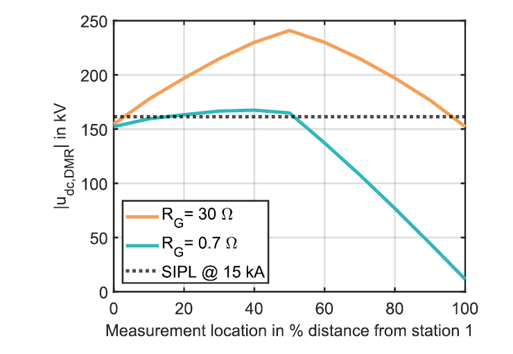
Figure 6 - Voltage profile along the metallic return cable during wort case fault F5. Pre-fault conditions: asymmetrical monopolar operation, power setpoint: -Prated.
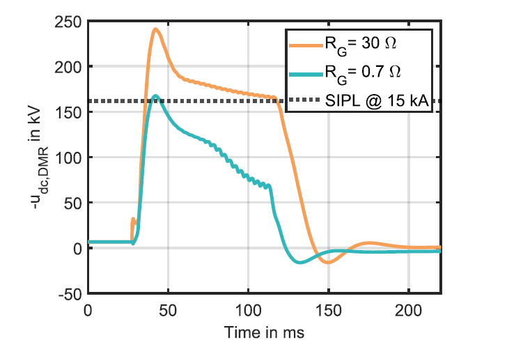
Figure 7 - Worst case overvoltage on the metallic return cable during fault F5. Pre-fault conditions: asymmetrical monopolar operation, power setpoint -Prated
As can be seen, the peak value of the overvoltage at both stations is limited by the SIPL of the NBA (dotted black line). But it is important to emphasize that a significant higher peak value can be observed along the cable route. In the event of F5, the overvoltage build-up along the metallic return cable is affected by travelling wave phenomena, as the converters of both stations block their IGBTs at nearly the same time instant. More detailed explanations on the overvoltage build-up during a cable fault in the middle of the cable route (F5) as a consequence of travelling waves caused by converter blocking can be found in [3]. Figure 7 shows the overvoltage waveshape measured at the spatial position of the highest peak value. The peak value of the overvoltage is approximately 50 percent higher than the switching impulse protective level of the NBA arresters located at the terminations of the metallic return cable.
For solid station grounding (RG = 0.7 Ω), the overvoltage levels experienced by metallic return cables are significantly lower compared to grounding concepts with additional grounding resistors. In addition, the spatial dependency of the overvoltage along the metallic return cable is less pronounced, see Figure 6. The highest peak value of the overvoltage is only slightly above the SIPL of the NBA.
Figure 8 and Figure 9 show characteristics overvoltages on the metallic return cable during converter internal faults and ac faults on converter valve side, respectively. During these fault events, the peak values of the overvoltages are limited mainly by the SIPL of the NBA. In the event of ac faults on converter valve side, a superimposed ac voltage is measured on the metallic return cable.
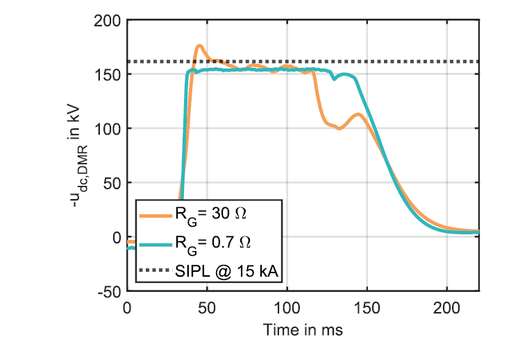
Figure 8 - Characteristic overvoltage on the metallic return cable during converter internal faults (F3 & F7). Pre-fault conditions: asymmetrical monopolar operation, power setpoint: +Prated & zero active power
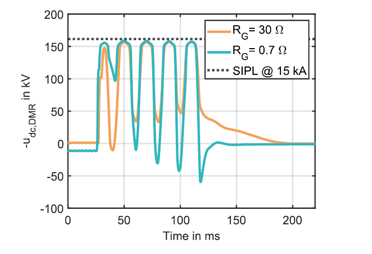
Figure 9 - Characteristic overvoltage on the metallic return cable during ac faults on transformer valve side (F2 & F8). Pre-fault conditions: asymmetrical monopolar operation, power setpoint: +Prated & zero active power
For all fault events, the metallic return cable experiences an overvoltage that decays after the ac circuit breakers of the faulty converter pole have cleared the fault. Consequently, the duration of the overvoltage depends on the maximum clearing time of the ac circuit breaker including potential back-up measures.
4.3. Protective Level of Neutral Bus Arresters
To demonstrate the impact of the neutral bus arrester (NBA) on occurring overvoltages, the parametric study is repeated for a different arrester coordination. Compared to the previous results under consideration of SIPL1 (162 kV at 15 kA discharge current), the switching impulse protective level of the NBAs is further increased (SIPL2: 247 kV at 15 kA discharge current). Figure 10 depicts the worst case overvoltages on the metallic return cable for the grounding concept through an additional grounding resistor and the impact of the arrester’s protective level. It is obvious that an increased protective level leads to higher overvoltages on the metallic return cable. For the considered 2-GW/±525-kV-HVDC scheme, highest overvoltage levels reach approximately 300 kV at the metallic return cable for SIPL2. It should be pointed out that the spatial location of the highest overvoltage can still be found in the middle of the cable route. Moreoever, the occuring peak value is significantly higher than the NBA's protective level.
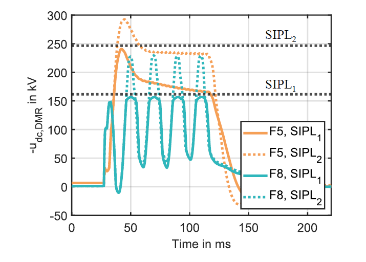
Figure 10 - Impact of protective level of the neutral bus arresters on metallic return cable overvoltages during different fault events (F5 & F8). Considered grounding concept: additional grounding resistor RG = 30 Ω. Pre-fault conditions: asymmetrical monopolar operation, power setpoint: +Prated & -Prated
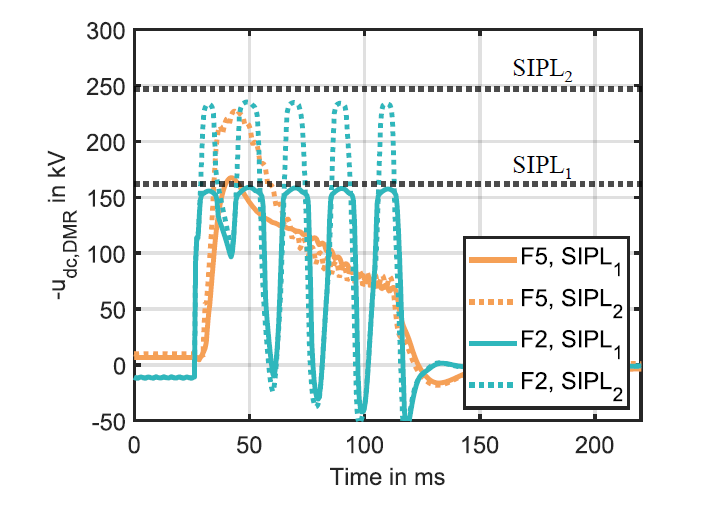
Figure 11 - Impact of protective level of the neutral bus arresters on metallic return cable overvoltages during different fault events (F5 & F2). Considered grounding concept: solid grounding RG = 0.7 Ω. Pre-fault conditions: asymmetrical monopolar operation, power setpoint: +Prated & -Prated
The worst case overvoltages for a solidly grounded neutral bus under consideration of both arrester layouts can be found in Figure 11. In case of solid station grounding, the maximum peak values of the overvoltages on metallic return cables are in the range of the NBA’ protective level. Obviously, an increased switching impulse protective level can provoke higher overvoltages on the metallic return cable.
As a conclusion, it must be stated that overvoltages on metallic return cables are strongly dependent on the design of the converter station. Therefore, the electrical interface between the cable system and the converter stations must be clearly specified, especially when tendering converter and cable separately, see also [14]. For the specification of the electrical requirements for metallic return cables, potential manufacturer-dependent designs of the converter station must be taken into account and an in-depth understanding about the transient system behavior of the converter stations is inevitable.
4.4. Further Parameters with an Impact on Overvoltages along Metallic Return Cables
The station grounding concept as well as the coordination of the neutral bus arresters represent the key design parameters with respect to overvoltages on metallic return cables. It is intended that this paper provides an initial indication of the expected peak values and overvoltage waveshapes for metallic return cables in the 2-GW/±525-kV-standard. However, for the sake of completeness it should be clarified that this paper is not intended to replace more detailed project specific studies. As already pointed out in Table 2, further project and manufacturer dependent parameters exist and need to be considered in more detailed project specific studies. It is to be expected that especially cable route length as well as rated ac voltage on transformer valve side are also very relevant parameters with regard to the transient system behavior during faults.
5. Conclusion
For MMC-HVDC systems, the bipolar configuration with dedicated metallic return will become the prevailing HVDC configuration if all envisaged projects are realized. To pave the way toward significant shorter project execution times and more standardized system designs, several European TSOs have awarded framework cooperation agreements to deliver a new generation of HVDC systems. This new generation of HVDC systems is often referred to as 2-GW/±525-kV-standard. In order to allow for redundancy and to ensure that the HVDC system can continue to operate at 50 percent of its rated power in the event of a cable fault, metallic return cables are inevitable in these upcoming projects. The current testing recommendation for HVDC cables leaves the specification of testing levels for metallic return cables open for the customer-supplier negotiation process and states that system calculations, taking into account the different fault scenarios, should be performed. This paper provides insights in basic design considerations of bipolar HVDC systems and assesses potential overvoltages on metallic return cables. Large parametric studies are conducted in order to examine critical overvoltages. Moreover, an initial indication of expected overvoltages on metallic return cables in the 2-GW/±525-kV-standard is provided. Overvoltages on metallic return cables are strongly dependent on the manufacturer-individual design of the converter station. The most important design parameters with regard to overvoltages on metallic return cables are the grounding concept of the neutral bus as well as the design of the neutral bus surge arresters. For station designs with an additional grounding resistor, peak values of the overvoltages on metallic return cables are in the range of 250 kV – 300 kV for the considered 2-GW/±525-kV-standard. It should be emphasized that maximum overvoltage levels can be significantly higher than the arrester's protective level and can occur in the middle of the cable route. In case of a solidly grounded neutral bus, overvoltages on metallic return cable are significantly reduced and lay in the range of the switching impulse protective level of the neutral bus arresters. Both considered grounding options of the neutral bus are conceivable realization concepts for bipolar MMC-HVDC schemes and represent a design compromise between fault current stresses of converter station equipment and cable overvoltages. Therefore, it has to be kept in mind that for the specification of insulation coordination requirements for metallic return cables, potential manufacturer-dependent designs of the converter station must be taken into account. Thus, it is recommended to clearly specify the electrical interface between the cable system and the converter stations and to carry out EMT-studies at an early stage of the project. In the next step, further discussions are needed, especially with the cable community, in order to evaluate the potential effects of the examined overvoltages on the insulation of metallic return cables. Also, similar studies are urgently needed for more complex HVDC arrangements.
6. Appendix
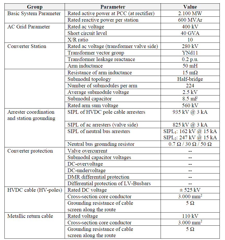
Table 3 - Selected parameters of the considered HVDC scheme
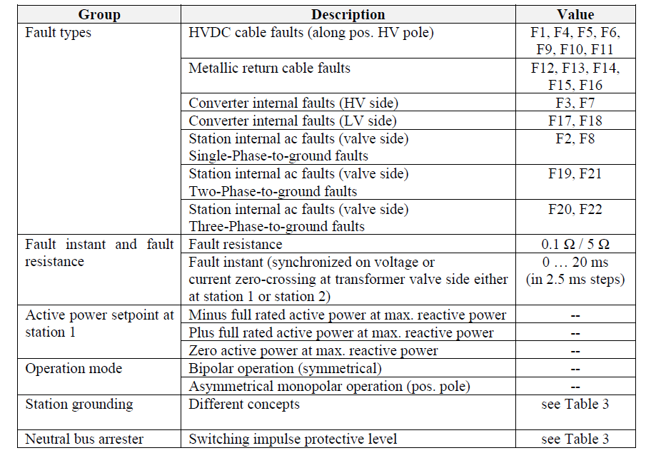
Table 4 - Parametric study setup
References
- H. Saad, P. Rault, M. Goertz and S. Wenig, "Parameter Sensitivity Analysis on DC Transients between MMC Station and Cable," Int. Conf. on Power Systems Transients (IPST'21), Jun. 2021.
- L. Colla, S. Lauria and F. Palone, "Short Circuit and Induced Voltage Transient Study on a Planned 1000 MW HVDC-VSC Cable Link," Int. Conf. on Power Systems Transients (IPST'11), Delft, Netherlands, Jun. 2011.
- M. Goertz, S. Wenig, S. Beckler, C. Hirsching, M. Suriyah, T. Leibfried, "Overvoltage characteristics in symmetrical monopolar HB MMC-HVDC configuration comprising long cable systems," Elsevier Electrical Power Sys. Research, Volume 189, Dec. 2020.
- M. Saltzer, M. Goertz, S. Wenig, W. Leterme, V. Joubert, H. Saad and et.al., "Overvoltages in Symmetric Monopolar HVDC Cable Systems – a Parameter Study Approach," CIGRE Symp. Aalborg, Jun. 2019.
- O. Sagosen, A. Craig, R. Poole and P. Paradine, "Need, design and business case for building the North Sea Link," ref B4-114_2018 CIGRE Paris Session 2018, Paris, France, 2018.
- M. Goertz, S. Wenig, S. Beckler, C. Hirsching, M. Suriyah and T. Leibfried, "Analysis of Cable Overvoltages in Symmetrical Monopolar and Rigid Bipolar HVDC Configuration," IEEE Trans. Power Del, vol. 35, no. 4, p. 2097–2107, 2020.
- M. Goertz et. al., "Analysis of Overvoltage Levels in the Rigid Bipolar MMC-HVDC Configuration," 13th IET International Conference on AC and DC Power Transmission (ACDC 2019), Coventry, UK, Feb., 2019.
- M. Saltzer, M. Goertz, S. Wenig, H. Saad, W. Leterme, J. Juvik et.al., "Overvoltages experienced by DC cables with an HVDC transmission system in a rigid bipolar configuration," Paris, France, Int. Conf. on Insul. Power Cables, Jicable'19, Jun. 2019.
- "German Grid Development Plan 2037, 2nd draft (available in German language only)," 50Hertz Transmission GmbH, Amprion GmbH, TenneT TSO GmbH, TransnetBW GmbH, 2023.
- "B1.62: Recommendations for testing DC extruded cable systems for power transmission at a rated voltage up to and including 800 kV, CIGRE Technical Brochure 852," CIGRE, Paris, France, Nov. 2021.
- G. Li, J. Liang, F. Ma, C. Ugalde-Loo and H. Liang, "Analysis of single-phase-to-ground faults at the valve-side of hb-mmcs in hvdc systems," IEEE Trans. Ind. Electron., vol. 66, no. 3, p. 2444–2453, 2019.
- J. Kjaergaard, "Bipolar operation of an HVDC VSC converter with an LCC converter," CIGRE B4 Colloquium, San Francisco, USA, 2012.
- G. Andersson and M. Hytinnen, "Skagerrak The next generation," CIGRE Symposium, Lund, Sweden, 2015.
- "B4.57: Guide for the development of models for HVDC converters in a HVDC grid," Technical Brochure 604 CIGRE, Paris, France, 2014.
- A. Morched, B. Gustavsen and M. Tartibi, "A Universal Model for Accurate Calculation of Electromagnetic Transients on Overhead Lines and Underground Cables," IEEE Trans. Power Del., vol. 3, p. 1032–1038, 1999.
- S. Beckler, J. Reisbeck and F. Exl, "Approach for a comprehensive definition of the electrical interface between HVDC converter and cable," Int. Conf. on Insulated Power Cables, Jicable'19, Paris, France, Jun. 2019.